
This Circular stipulates the measurement of control points of remote sensing images in national remote sensing activities, including the contents such as layout and connection measurement of images, correction of control points on images, inspection, acceptance, and submission of results. This Circular takes effect from July 24, 2017.
Đối tượng áp dụng
Ministries, ministerial-level agencies, government agencies; People's Committees of provinces and centrally governed cities under the central government, and organizations and individuals related to national remote sensing activities.
Các điểm cốt lõi
- Provisions on the layout and connection measurement of remote sensing images
- Requirements for correcting control points on remote sensing images
- Inspection and acceptance procedures for control point measurement results of remote sensing images
- Contents to be submitted upon completion of remote sensing image control point measurement work.
- Effective date from July 24, 2017
🌐 Tác động xã hội từ văn bản này
- To ensure the quality and accuracy of remote sensing data
- Provide a legal basis for the measurement of control points of remote sensing images in national remote sensing activities.
- Support management and monitoring of natural resources and environmental sustainable development.
❓ Câu hỏi thường gặp
When does this Circular take effect?
This Circular takes effect from July 24, 2017.
Who must implement this Circular?
Ministries, ministerial-level agencies, government agencies; People's Committees of provinces and centrally governed cities under the central government, and organizations and individuals related to national remote sensing activities.
What are the main contents of this Circular?
This Circular stipulates the measurement of control points of remote sensing images in national remote sensing activities, including layout and connection measurement of images, correction of control points on images, inspection, acceptance, and submission of results.
Toàn văn
|
MINISTRY OF NATURAL RESOURCES AND ENVIRONMENT |
SOCIALIST REPUBLIC OF VIET NAM |
|
Number: 08/2017/TT-BTNMT |
Hanoi, June 6, 2017 |
CIRCULAR
Regulations on the control surveying process for remote sensing images
Pursuant to Decree No. 36/2017/NĐ-CP dated April 4, 2017 of the Government on the functions, tasks, powers, and organizational structure of the Ministry of Natural Resources and Environment;
Pursuant to Decision No. 81/2010/QĐ-TTg dated December 13, 2010 of the Prime Minister on the collection, storage, processing, exploitation, and utilization of national remote sensing data; Decision No. 76/2014/QĐ-TTg dated December 24, 2014 of the Prime Minister amending and supplementing certain articles of Decision No. 81/2010/QĐ-TTg dated December 13, 2010 of the Prime Minister on the collection, storage, processing, exploitation, and utilization of national remote sensing data;
AT THE REQUEST OF THE DIRECTOR OF THE NATIONAL REMOTE SENSING CENTER, THE HEAD OF THE SCIENCE AND TECHNOLOGY DEPARTMENT, AND THE HEAD OF THE LEGAL AFFAIRS DEPARTMENT;
The Minister of Natural Resources and Environment promulgates this Circular stipulating the control surveying process for remote sensing images.
PART I
GENERAL PROVISIONS
Article 1. Scope of Regulation
This Circular specifies the contents and procedures for implementing the control surveying of remote sensing images, and serves as a legal basis for managing, reviewing, and approving projects, economic and technical feasibility studies, and establishing economic and technical norms that utilize control surveying of remote sensing images.
Article 2. Applicability
This Circular applies to state management agencies; organizations and individuals related to the control surveying of remote sensing images within the territory of Vietnam.
Article 3. Explanation of Terms
In this Circular, the following terms are understood as follows:
1. A control point for remote sensing images is a geographic feature marked on a remote sensing image and simultaneously determined in the National Coordinate System VN-2000 and the National Height System.
2. GNSS (Global Navigation Satellite System) is a global satellite navigation system.
3. RINEX (Receiver INdependent EXchange format) is a standard GNSS measurement data format using ASCII code for convenient processing independent of receivers or software.
Chapter II
CONTROL SURVEYING PROCESS FOR REMOTE SENSING IMAGES
Article 4. Diagram of the control surveying process for remote sensing images
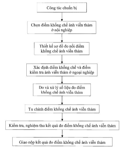
Diagram 1: Diagram of the control surveying process for remote sensing images
Article 5. Preparation Work
1. Determine the area for control surveying of remote sensing images.
2. Collect materials including:
a) Remote sensing images of the control surveying area;
b) Diagrams, coordinates, and heights of existing national coordinate points and height points in the control surveying area;
c) Technical design and other relevant technical documents;
d) The latest topographic map of the control surveying area.
3. Determine the method of control surveying for remote sensing images, which includes static GNSS measurement technology or traverse method using electronic total stations or electronic theodolites according to the technical design.
4. Check the surveying equipment for control surveying of remote sensing images:
a) GNSS signal receiving devices used in control surveying of remote sensing images must have valid calibration certificates;
b) Electronic total stations, electronic theodolites, Invar tapes, steel tapes must have valid calibration certificates;
c) Equipment must be checked before conducting control surveying of remote sensing images. Inspection documents must be kept with the results of the control surveying of remote sensing images.
Article 6. Selection of control points for remote sensing images in office work
The selection of control points for remote sensing images and the layout diagram of control points for remote sensing images must comply with the provisions of Clause 1 and Point a, Point b, Clause 2 of Article 9 of Circular No. 10/2015/TT-BTNMT dated March 25, 2015 of the Minister of Natural Resources and Environment on optical high-resolution and ultra-high-resolution remote sensing image production techniques to provide to users.
Article 7. Designing the layout for connecting control points in remote sensing images
1. On the layout for connecting measurements, it must show the scenes of remote sensing images within the area to be controlled, scene numbers, existing origin points in the area, remote sensing image control points, newly designed check points, and connection measurement directions.
2. Depending on the measurement method, type of measuring instrument, and number of measuring instruments, design the layout for connecting measurements. The measurement area can be divided into smaller clusters for convenience during the connection process.
3. Designing the route for connecting control points of remote sensing images:
a) Collect the latest topographic map covering the area where the remote sensing image control measurements are arranged on the day of measurement. Plan the measurement sessions appropriately according to the measurement time and taking into account the travel time between control image measurement positions;
b) Design the movement route between the original control image measurement positions and the connecting control image measurement positions.
4. Designing the measurement of remote sensing image control points:
a) Measurement using GNSS technology:
Before conducting the measurement, a schedule must be established and a satellite observation forecast table must be created;
Based on the number of receivers, the GNSS measurement grid design diagram, and the satellite forecast table, create a measurement scheduling table with contents including: measurement time, station data, station name, receiver data, etc...
b) Measurement using traverse method with electronic total stations or electronic theodolites:
When measuring remote sensing image control points using the traverse method, based on the density of initial points, the design can be in the form of a single traverse or a network depending on the terrain conditions;
Parameters must be stated in the technical design - budget estimate or construction plan in accordance with Table 2 of Article 10 of this Circular.
Article 8. Determination of Control Points and Check Points in Fieldwork
1. Locate and determine the connection control points, remote sensing image control points, and check points in fieldwork. Remote sensing control points and check points must be marked with wooden stakes or painted marks on-site (wooden stakes with a diameter of at least 3 cm and a cross-shaped nail at the center, if painted marks are used, the paint stroke should not exceed 1 cm), ensuring they remain intact during the construction and inspection period.
2. Remote sensing control points and check points must ensure they can be accurately identified up to 0.5 pixels on remote sensing images and there should be no changes in position during the construction process.
3. Remote sensing image control points and check points must be marked directly on the image at the site.
Article 9. Measuring and processing data of remote sensing image control points using GNSS technology
1. Measuring remote sensing image control points:
a) Remote sensing image control points must be arranged for connection from two national coordinate points of class III or higher or basic cadastral points;
b) Receivers at the origin points must continuously transmit signals throughout the measurement sessions;
c) Conduct remote sensing image control point measurements according to points 6.2, 6.3, 6.4, 6.5, 6.6 of Section 6, Part II of Circular No. 06/2009/TT-BTNMT dated June 18, 2009, issued by the Minister of Natural Resources and Environment regarding national technical standards for establishing coordinate grids;
d) At the field measurement station, detailed records must be kept according to the sections of the measurement logbook. Entries in the logbook must be clear, accurate, neat, and not erased; if an error occurs, the incorrect number must be crossed out and the correct number written above while noting the cause. The GNSS measurement logbook format is specified in Appendix 7 of Circular No. 06/2009/TT-BTNMT dated June 18, 2009, issued by the Minister of Natural Resources and Environment regarding national technical standards for establishing coordinate grids.
2. Calculating the accuracy of remote sensing image control points:
a) When using receivers from different manufacturers to measure remote sensing image control points, measurement data must be converted to the same RINEX format;
b) Process data, calculate edge vectors: in synchronous measurement sessions with multiple receivers, individual edge vectors can be calculated separately, or independent edge vectors can be selected and processed together;
c) Software for calculating and processing remote sensing image control point measurement data must be compatible with the type of satellite signal receiver to automatically calculate edge vectors; d) The accuracy assessment of remote sensing image control points is carried out after summarizing the edge length and closure errors for the entire network meeting technical criteria;
đ) Calculating the accuracy of the remote sensing image control network using GNSS measurement technology must meet the requirements for accuracy as stipulated in Table 1.
Accuracy Criteria
|
Serial number |
Technical Specifications |
Static Measurement |
|
1 |
Measurement method |
Using receivers with absolute edge measurement value |
|
2 |
(D: distance in kilometers) 10mm + 2.10 |
Number of usable satellites-6Domestic air passenger transport service on regular basic economy class |
|
3 |
Maximum PDOP |
≥ 4 |
|
4 |
Satellite elevation angle threshold ( |
≤ 4 |
|
5 |
Simultaneous observation time°) |
≥ 15 |
|
6 |
≥ 60 minutes |
Maximum distance from a remote sensing image control point to the nearest higher-order control point |
|
7 |
≤ 30 km |
Number of independent edges at a point |
|
8 |
Post-adjustment positional error of remote sensing image control points relative to the nearest national coordinate control point |
≥ 2 |
|
9 |
≤ 0.2 pixel |
Table 1: Basic technical requirements when using GNSS technology |
Table 1: Basic technical requirements when using GNSS technology
Article 10. Measurement and processing of control point data for remote sensing images using electronic total stations or electronic theodolites
1. Measurement of control points for remote sensing images
Using electronic total stations or electronic theodolites to measure control points for remote sensing images according to the designed traverse network. When using electronic total stations or electronic theodolites to measure control points and check points, technical specifications must be followed as stipulated in Circular No. 68/2015/TT-BTNMT dated December 22, 2015, issued by the Minister of Natural Resources and Environment on technical regulations for direct topographic surveying to serve the creation of topographic maps and geographic base databases at scales of 1:500, 1:1000, 1:2000, and 1:5000.
2. Calculating the accuracy of remote sensing image control points:
a) The measurement results are initially calculated using the approximate least squares method. If the angle closure error or the traverse closure error, relative traverse closure error reaches the permissible limit, then these measurement results can be used for precise least squares adjustment;
b) Traverse control network adjustment calculations shall be performed using the traverse measurement technology specified in Table 2.
|
Serial number |
Technical Specifications |
Static Measurement |
|
1 |
Traverse deflection angle |
≥ 30° (degrees) |
|
2 |
Number of traverse sides |
≤ 15 |
|
3 |
Traverse length: - Connecting two high-order points - Perimeter of closed traverse |
≤ 8 km ≤ 20 km |
|
4 |
Traverse length: - Longest side - Shortest side - Average side length |
≤ 1.400 m ≥ 200 m 500-700 m |
|
5 |
Absolute mean error of angle measurement |
≤ 5 seconds |
|
6 |
Absolute limit closure error of traverse angle (n: number of angles in the closed traverse) |
≤ 5 seconds
|
|
7 |
Relative closure error fs/[s] |
≤ 1:25.000 |
|
8 |
≤ 0.2 pixel |
Table 1: Basic technical requirements when using GNSS technology |

Table 2: Basic technical requirements when using the traverse method
Article 11. Adjustment of remote sensing image control points
All remote sensing image control points and check points must be adjusted on both sides of the image. The diameter of the punch hole must not exceed 0.15 mm on the image.
1. On the right side of the remote sensing image: positions of all points are circled and named with non-fading ink. National coordinate points and national elevation points used as bases for measuring remote sensing image control points are punched onto the right side of the remote sensing image according to Figure 2.
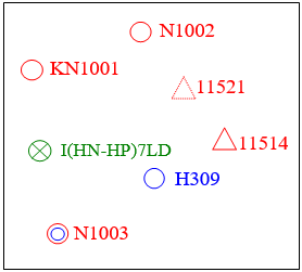
Figure 2. Adjustment of remote sensing image control points on the right side of the remote sensing image
a) N1002 is the name of the planimetric control point (indicated by a red circle with a diameter of 01 (one) cm and a red point number);
b) H309 is the name of the elevation control point (indicated by a blue circle with a diameter of 01 (one) cm and a blue point number);
c) N1003 is the name of the planimetric and elevation control point (indicated by an outer red circle with a diameter of 01 (one) cm, an inner blue circle with a diameter of 0.6 (six-tenths) cm, and a red point number);
d) 11514 is the name of the national coordinate point (indicated by a red triangle with each side measuring 01 (one) cm and a red point number);
đ) 11521 is the name of the national coordinate point that cannot be accurately punched on the remote sensing image (indicated by a dashed red triangle with each side measuring 01 (one) cm and a red point number);
e) I(HN-HP)7LD is the name of the national elevation point (indicated by a green circle with a diameter of 01 (one) cm and a green point number);
g) KN1001 is the name of the check point for image control (indicated by a red circle with a diameter of 01 (one) cm and a red point number).
2. On the left side of the remote sensing image: the annotation diagram drawn with black ink is magnified 2 to 4 times compared to the scale on the right side of the remote sensing image. The lines and background of the diagram must be similar to those on the image. In the annotations, the point number, detailed position description, and puncher's name must be clearly recorded. Squares with dimensions of 3x3 cm are provided as specified in Figure 3.
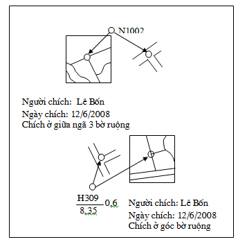
Figure 3. Adjustment of remote sensing image control points on the left side of the remote sensing image
a) N1002 is the name of the planimetric control point;
b) H309 is the name of the elevation control point;
c) 8,35 is the elevation of the control point;
d) 0,6 is the ratio height or depth of the control point.
Article 12. Inspection and Acceptance of Remote Sensing Image Control Point Measurement Results
Prior to submitting the remote sensing image control point measurement results, an inspection and acceptance of the products must be conducted in accordance with Circular No. 63/2015/TT-BTNMT dated December 21, 2015, issued by the Minister of Natural Resources and Environment on guiding inspection, evaluation, and acceptance of surveying and mapping works and products.
Article 13. Submission of Remote Sensing Image Control Point Measurement Results
1. The submission of remote sensing image control point measurement results using GNSS technology includes:
a) Layout diagrams and connected control point measurements of remote sensing images in paper and digital formats;
b) Corrected images of each remote sensing image control point at a large scale on A4 paper;
c) GNSS measurement book;
d) Raw measurement data and RINEX format data of remote sensing image control points recorded on storage devices;
đ) Preliminary processing results and officially corrected three-value X, Y, Z coordinate results recorded on storage devices, including intermediate files created during the correction process;
e) Surveying, calculation, and correction results of remote sensing image control points and check points must be approved inspection and acceptance results meeting quality standards, bearing the stamp and signature of the construction unit in both paper and digital formats, including seven (07) tables as stipulated in Clause 3.9, Section 3, Part III of Circular No. 06/2009/TT-BTNMT dated June 18, 2009, issued by the Minister of Natural Resources and Environment on national technical standards for establishing coordinate networks.
2. The submission of remote sensing image control point measurement results using electronic total stations or electronic theodolites includes:
a) Layout diagrams and connected control point measurements of remote sensing images in paper and digital formats;
b) Corrected images of each remote sensing image control point at a large scale on A4 paper;
c) Angle measurement book and traverse distance measurement book;
d) Table of edge lengths, edge azimuths, and post-correction errors;
đ) Post-correction planar orthogonal coordinates table;
e) Surveying, calculation, and correction results of remote sensing image control points and check points must meet quality standards as specified in Circular No. 63/2015/TT-BTNMT dated December 21, 2015, issued by the Minister of Natural Resources and Environment on inspection, evaluation, and acceptance of surveying and mapping works and products, including: Angle measurement book and traverse distance measurement book; Table of edge lengths, edge azimuths, and post-correction errors; Post-correction planar orthogonal coordinates table; Layout diagram of remote sensing image control point network.
3. All submitted results must bear the name and signature of the measurer, calculator, and completion date. They must also have the signature and seal of the head of the directly supervising unit.
Chapter III
IMPLEMENTING PROVISIONS
Article 14. Effective Date
This Circular takes effect from July 24, 2017.
Article 15. Implementation Organization
1. Ministries, ministerial-level agencies, government-affiliated agencies; People's Committees of provinces and centrally governed cities, and related organizations and individuals are responsible for implementing this Circular.
2. The National Remote Sensing Center, Ministry of Natural Resources and Environment is responsible for guiding and inspecting the implementation of this Circular.
3. During the implementation of this Circular, if there are any difficulties, relevant agencies, organizations, and individuals are requested to promptly report to the Ministry of Natural Resources and Environment for consideration and decision.
|
Place of Receipt: |
DEPUTY MINISTER DEPUTY MINISTER (Signed) Nguyen Linh Ngoc |
Văn bản gốc (PDF)
Tải văn bản
Bản đồ quan hệ
Bấm vào một văn bản để mở. Viền đỏ = quan hệ làm thay đổi hiệu lực.
Bản dịch
Văn bản này có sẵn ở các ngôn ngữ sau: