
Circular No. 09/2021/TT-BTTTT promulgates the National Technical Regulations on Radar Equipment Operating in the Frequency Band from 76 GHz to 77 GHz for Ground Transport Vehicles, stipulating technical requirements and testing methods for such equipment.
Scope of application
Manufacturers, importers, installers, and users of radar equipment operating in the frequency band from 76 GHz to 77 GHz for ground transport vehicles
Key points
- Manufacturers and importers must comply with the technical requirements regarding the operating frequency range (Article 2.3.1)
- The average power of the transmitter shall not exceed the specified level (Article 2.3.2)
- Unwanted emissions in out-of-band and spurious regions must be within permissible limits (Article 2.3.4, Article 2.3.5)
- The receiver must meet the requirements concerning spurious receiver emissions and in-band, out-of-band, and remote control signals (Article 2.4.1, Article 2.4.2)
- Organizations responsible for conducting tests according to the methods prescribed in this Circular (Article 3)
🌐 Social impact of this document
- Enhance the management of quality for radar equipment operating in the frequency band from 76 GHz to 77 GHz, ensuring safety and effective use
- Non-compliance with new technical standards may cause difficulties for manufacturing and importing enterprises
❓ Frequently asked questions
What technical requirements must manufacturers of radar equipment comply with?
Must comply with requirements regarding the operating frequency range, average and peak power, and unwanted emissions in out-of-band and spurious regions (Article 2.3)
What is the specific limit for the average power of the radar transmitter?
The specific limit for average power is set forth in Article 2.3.2
How must manufacturers conduct testing?
Must comply with the testing methods prescribed in this Circular (Article 3)
Full text
|
MINISTRY OF INFORMATION AND COMMUNICATION COMMUNICATION |
SOCIALIST REPUBLIC OF VIET NAM Independence - Freedom - Happiness |
|
Number: /2021/TT-BTTTT |
Hanoi, on the year 2021 |
CIRCULAR
Issuing the "National Technical Regulation on Radar Equipment Operating in the Frequency Range from 76 GHz to 77 GHz for Ground-Based Vehicles"
Based on Decree No. 78/2018/NĐ-CP dated May 16, 2018 of the Government amending and supplementing some articles of Decree No. 127/2007/NĐ-CP dated August 1, 2007 of the Government detailing the implementation of certain provisions of the Law on Standards and Technical Regulations;
Pursuant to the Law on Standards and Technical Regulations dated June 29, 2006;
Pursuant to the Law on Telecommunications dated November 23, 2009;
WHEREAS, the Law on Radio Frequency Spectrum dated November 23, 2009;
WHEREAS, Decree No. 127/2007/NĐ-CP dated August 1, 2007 of the Government detailing and guiding the implementation of certain provisions of the Law on Technical Standards and Regulations;
The Minister of Information and Communications issues this Circular stipulating the National Technical Regulation on Radar Equipment Operating in the Frequency Range from 76 GHz to 77 GHz for Ground-Based Vehicles.
Pursuant to Decree No. 17/2017/NĐ-CP dated February 17, 2017, issued by the Government, on the functions, tasks, powers, and organizational structure of the Ministry of Information and Communications;
Pursuant to the proposal of the Director of the Science and Technology Department,
Along with this Circular, the National Technical Regulation on Radar Equipment Operating in the Frequency Range from 76 GHz to 77 GHz for Ground-Based Vehicles (QCVN 124:2021/BTTTT) is issued.Scope of service activity The Heads of the Office, Department of Science and Technology, Heads of agencies and units under the Ministry of Information and Communications, Directors of Provincial Departments of Information and Communications, and relevant organizations and individuals are responsible for implementing this Circular.
Clause 4 of Article 6- Official Gazette, Government Portal;
12/2025/TT-BNNMT dated June 19, 2025 issued by the Minister of Agriculture and EnvironmentThis Circular takes effect from July 1, 2022.
Article 3. - To be filed: VT, KHCN (250).
|
Place of receipt: - Prime Minister, Deputy Prime Ministers (for circulation); - Ministries, agencies equivalent to ministries, and government agencies; - People's Committees of provinces and centrally governed cities; - Provincial Departments of Information and Communications; - Legal Documents Supervision Bureau (Ministry of Justice); QCVN 124:2021/BTTTT - Ministry of Information and Communications: Ministers, Deputy Ministers, departments and units under the Ministry, the Ministry's electronic portal; ON RADAR EQUIPMENT OPERATING IN THE FREQUENCY RANGE FROM 76 GHz TO 77 GHz FOR GROUND-BASED VEHICLES |
THE MINISTER (Signed) Nguyen Manh Hung |
SOCIALIST REPUBLIC OF VIET NAM
on Radar equipment operating in the frequency range
AMENDMENT 1:2025 QCVN 07:2023/BXD
76 GHz to 77 GHz
National technical regulation for ground based vehicle Table of Contents1. GENERAL PROVISIONS... 5
HANOI - 2021
1.1. Scope of Application... 5
1.2. Applicability... 5
1.3. Referenced Documents... 5
1.4. Definitions... 6
1.5. Symbols... 8
1.6. Abbreviations... 9
2. TECHNICAL REQUIREMENTS... 10
2.1. Environmental Conditions... 10
2.2. General Provisions... 10
2.3. Requirements for Transmitter... 11
2.3.1. Operating Frequency Band... 11
2.3.2. Average Power... 11
2.3.3. Peak Power... 12
2.3.4. Unwanted Emissions Outside the Band... 12
2.3.5. Unwanted Emissions in the Spurious Domain... 13
2.4. Requirements for Receiver... 14
2.4.1. Spurious Emissions from the Receiver... 14
2.4.2. In-band, Out-of-band, and Remote Control Signals of the Receiver... 15
3. TESTING METHODS... 16
3.1. Testing for Transmitter... 16
3.1.1. Operating Frequency Band... 16
3.1.2. Average Power... 16
3.1.3. Peak Power... 17
3.1.4. Unwanted Emissions Outside the Band... 18
3.1.5. Unwanted Emissions in the Spurious Domain... 19
3.2. Testing for Receiver... 19
3.2.1. Spurious Emissions from the Receiver... 19
3.2.2. In-band, Out-of-band, and Remote Control Signals of the Receiver... 20
4. MANAGEMENT PROVISIONS... 21
5. RESPONSIBILITIES OF ORGANIZATIONS AND INDIVIDUALS... 21
6. IMPLEMENTATION ORGANIZATION... 21
Appendix A (Provisions) General Conditions... 23
Appendix B (Provisions) Test Setup and Procedure... 30
Appendix C (Provisions) Measurement Areas and General Layouts for Measurements Related to the Use of Radiation Fields... 33
Appendix D (Provisions) Standard Testing Methods... 40
Appendix E (Provisions) Calculation of Rx Path... 42
Appendix F (Provisions) Receiver Tester... 45
Appendix G (Provisions) Harmonized System (HS) Code for Radar Equipment Operating in the Frequency Range from 76 GHz to 77 GHz for Ground-Based Vehicles... 48
References... 49
Foreword QCVN 124:2021/BTTTT was compiled by the Telecommunications Department, reviewed by the Department of Science and Technology, and approved by the Minister of Information and Communications through Circular No. .../2021/TT-BTTTT dated ... month ... year 2021.
NATIONAL TECHNICAL REGULATION
ON RADAR EQUIPMENT OPERATING IN THE FREQUENCY RANGE FROM 76 GHz TO 77 GHz
FOR GROUND-BASED VEHICLES
on Radar equipment operating in the frequency range 76 GHz to 77 GHz for ground-based vehicle
This regulation specifies detailed technical characteristics and testing methods for radar equipment using integrated antennas operating in the frequency range from 76 GHz to 77 GHz for ground-based vehicles. This regulation applies to integrated transmitter-receiver equipment.
National technical regulation This regulation also sets requirements for short-range wireless devices used in ground-based vehicles, such as active cruise control systems, collision warning systems, blind spot detection systems, parking assistance systems, backup assistance systems, and future applications.
Chapter 1. GENERAL PROVISIONS
1.1. Scope of Application
This regulation does not cover all possible characteristics that may be required by users, nor does it fully represent the optimal performance that the equipment can achieve.
In case of discrepancies (for example, related to special conditions, definitions, abbreviations) between this regulation and other regulations, the provisions of this regulation shall take precedence.
These types of radar equipment have the capability to operate across all or part of the frequency bands listed in Table 1.
Table 1 - Operating Frequency Bands of Equipment
Operating Frequency Band
Transmission
76 GHz – 77 GHz
The Harmonized System (HS) code for radar equipment operating in the frequency range from 76 GHz to 77 GHz for ground-based vehicles is specified in Appendix G.
This regulation applies to domestic and foreign organizations and individuals engaged in production and business activities involving equipment within the scope of this regulation on the territory of Vietnam.
Vehicle
This regulation applies to domestic and foreign organizations and individuals engaged in production and business activities involving equipment within the scope of this regulation on the territory of Vietnam.
CEPT/ERC Recommendation 70-03: "Regarding the use of Short Range Devices (SRD)"
1.2. Applicability
EC Decision 2013/752/EU: "Commission Implementing Decision of 11 December 2013 amending Decision 2006/771/EC on harmonization of the radio spectrum for use by short-range devices and repealing Decision 2005/928/EC"
1.3. Referenced Documents
CEPT/ERC/REC 74-01: "Unwanted emissions in the spurious domain"
CISPR 16-1-1 (2006), CISPR 16-1-4 (2010) and CISPR 16-1-5 (2014): "Specifications for radio disturbance and immunity measuring apparatus and methods; Part 1: Radio disturbance and immunity measuring apparatus"
CEPT/ERC/REC 74-01: "Unwanted emissions in the spurious domain".
CISPR 16-1-1 (2006), CISPR 16-1-4 (2010) and CISPR 16-1-5 (2014): "Specification for radio disturbance and immunity measuring apparatus and methods; Part 1: Radio disturbance and immunity measuring apparatus".
ETSI TR 100 028 (V1.4.1) (all parts): "Electromagnetic compatibility and Radio Spectrum Matters (ERM); Uncertainties in the measurement of mobile radio equipment characteristics".
ETSI TR 102 273 (V1.2.1) (all parts): "Electromagnetic compatibility and Radio Spectrum Matters (ERM); Improvement on Radiated Methods of Measurement (using test site) and evaluation of the corresponding measurement uncertainties".
Recommendation ITU-R SM.329-12 (2012): "Unwanted emissions in the spurious domain".
Recommendation ITU-R SM.328-11 (2006): "Spectra and Bandwidth of Emissions".
1.4. Terms and Definitions
1.4.1. Antenna cycle (ăng ten cycle)
The antenna cycle is a complete sweep of the beam through a predetermined spatial pattern of a mechanically or electronically scanned antenna.
1.4.2. Antenna scan duty factor (hệ số phụ tải ăng ten quét)
The antenna scan duty factor is the fixed angular width of the antenna beam (measured at the 3 dB point) relative to the total fixed angle swept by the antenna.
1.4.3. Averaging time (thời gian trung bình)
Averaging time is the preset period of time for the measurement averaging.
1.4.4. Boresight (hướng trục ăng ten)
The boresight is the direction that achieves the maximum gain of a directional antenna.
NOTE: The EUT may have different boresights for transmit and receive antennas.
1.4.5. Co-located receiver (máy thu cùng vị trí)
A co-located receiver is a receiver located within the same housing with the transmitter.
1.4.6. Cycle time (chu kỳ thời gian)
The cycle time is the duration between periodic transmission patterns of the system.
NOTE: In the case of random patterns, the default value used is 1 minute.
1.4.7. Duty cycle (chu kỳ hoạt động)
The duty cycle is calculated by the formula: ∑(T)/ t_o. Where: T is the ON time of a transmission and t_o is the observation period. T is measured within an observation bandwidth (BW_o).on)/ t_o. Where: Ton is the ON time of a transmission and t_o is the observation period. Ton is measured within an observation bandwidth (BW_o).
1.4.8. Equipment Under Test (EUT) (thiết bị cần đo kiểm)
The Equipment Under Test (EUT) is a radar sensor including an integrated antenna together with any external antenna components that affect or influence its performance.
1.4.9. Equivalent Isotropically Radiated Power (e.i.r.p.) (công suất bức xạ đẳng hướng tương đương)
The Equivalent Isotropically Radiated Power (e.i.r.p.) is the component of the power delivered to the antenna and the gain of the antenna in a given direction compared to an isotropic or omnidirectional antenna.
NOTE: e.i.r.p. can be used for peak or average power and peak or average power spectral density. If not otherwise specified, e.i.r.p. refers to average power.
1.4.10. Far Field Measurement (đo trường xa)
A far field measurement is a measurement at a distance from the antenna sufficient to ensure that the electric field is nearly plane.
1.4.11. Illumination Time (thời gian chiếu xạ)
For equipment with a scanned antenna, the illumination time is the time during which a specific point in the far field remains within the main beam of the antenna.
1.4.12. Maximum Power (công suất lớn nhất)
The maximum power is the highest average power related to azimuth and elevation angles (usually measured at the boresight of the antenna).
1.4.13. Mean Power (công suất trung bình)
The mean power is the power over a sufficiently long period of time relative to the lowest modulation carrier frequency.
NOTE: For pulse or phase-shift systems without additional carrier modulation, the mean power equals the peak envelope power (see ITU Radio Regulations [RR] 1.157) multiplied by the duty factor. For continuous wave (CW) systems without off times, the mean power equals the transmitted power without modulation.
1.4.14. Operating Frequency (Operating Centre Frequency) (tần số hoạt động (tần số trung tâm))
The operating frequency is the nominal operating frequency of the device.
NOTE: The device may operate at one or more frequencies.
1.4.15. Operating Frequency Range (dải tần số hoạt động)
The operating frequency range is the band within which the device can be adjusted via switching or reprogramming or oscillator tuning.
NOTE 1: For pulse or phase-shift systems without additional carrier modulation, the operating frequency range is fixed on a single channel.
NOTE 2: For analog or discrete frequency-modulated (FSK, FMCW) systems, the operating frequency range includes the band from the lowest to the highest frequency modulated across all carrier frequencies of the device.
1.4.16. Peak Power (công suất đỉnh)
The peak power is the instantaneous highest power of the EUT.
1.4.17. Permitted Frequency Range (dải tần cho phép)
The permitted frequency range is the bands of frequencies within which the device is allowed to operate.
1.4.18. Power Envelope (đường bao công suất)
The power envelope is the power supplied to the antenna of the transmitter throughout the transmission period, taken at the peak of the modulation envelope under normal operating conditions.
1.4.19. Power Spectral Density (mật độ phổ công suất)
Power spectral density is the ratio of power to the radio bandwidth used for measurement.
1.4.20. Pulse Radar (ra đa xung)
Pulse radar is a radar that determines range based on the time of flight of short radar pulses that are not frequency modulated.
1.4.21. Radar Cross Section (RCS) (mặt cắt ngang ra đa)
The Radar Cross Section (RCS) is the cross-sectional area of a reflecting sphere that would produce the same reflected intensity to the illuminated object.
1.4.22. Scanning (Steerable) Antenna (ăng ten quét (có thể điều khiển))
A scanning antenna is a directional antenna that can move its beam along a predetermined spatial path.
NOTE: Scanning can be performed by mechanical, electronic, or combined means. The antenna beamwidth may remain constant or vary with steering angle, depending on the steering method.
1.4.23. Second (2nd) Harmonic (hài bậc 2 (thứ 2))
The second (2nd) harmonic is a harmonic having a frequency twice that of the fundamental frequency (for example, 48 GHz for a 24 GHz device).
1.4.24. Ground Based Vehicle (phương tiện vận tải trên mặt đất)
A ground-based vehicle includes but is not limited to passenger vehicles, buses, trucks, rail vehicles, electric vehicles, ships, construction vehicles, and aircraft when parked.
1.4.25. Occupied bandwidth
Occupied bandwidth is the width of the frequency band within which the average power emitted at frequencies below the lower edge and above the upper edge of that band equals a predetermined percentage β/2 of the total average emission power.
Unless otherwise specified, the value of β/2 is selected as 0.5%.
1.4.26. Integral antenna
An integral antenna is an antenna designed to be connected to equipment without using standard connectors and is considered part of the equipment.
1.5. Symbols
|
l |
Wavelength |
|
|
B |
Bandwidth (pulse) |
|
|
For coal-fired thermal power plants where the enterprise holds 100% of the registered capital and uses 100% of its own capital to invest in the project approved by the competent authority, E is determined as 100%; |
Maximum aperture diameter of the antenna |
|
|
dB |
Decibel |
|
|
For coal-fired thermal power plants where the enterprise holds 100% of the registered capital and uses 100% of its own capital to invest in the project approved by the competent authority, E is determined as 100%;FF |
Far field distance |
|
|
D |
Scanning antenna load factor |
|
|
E |
Electric field strength |
|
|
fof |
Carrier frequency |
|
|
fH |
Highest frequency |
|
|
fL |
Lowest frequency |
|
|
F |
Permitted frequency bandwidth |
|
|
F1 |
Lower boundary between the OOB region and the adjacent region |
|
|
F2 |
Upper boundary between the OOB region and the adjacent region |
|
|
BW_o |
Observed bandwidth |
|
|
"5. The pre-tax weighted average cost of capital i (%) is determined according to the formula below:CORR |
Measured power corrected relative to RBW |
|
|
"5. The pre-tax weighted average cost of capital i (%) is determined according to the formula below:MEASURED |
Measured power |
|
|
RBW |
Resolution bandwidth |
|
|
RBWREF |
Reference resolution bandwidth |
|
|
RBWMEASURED |
Resolution bandwidth used for measurements |
|
|
t_o |
Observation time |
|
1.6. Abbreviations
|
AC |
Alternating Current |
Continuous phenomenon applicable to receivers |
|
BW |
BandWidth |
Bandwidth |
|
CEPT |
European Conference of Postal and Telecommunications Administrations |
European Post and Telecommunications Administrations Association |
|
CISPR |
International Special Committee on Radio Interference |
Special International Committee on Radio Interference |
|
CW |
Continuous Wave |
Continuous wave |
|
DC |
2.1 Electromagnetic Compatibility (EMC) Emission |
Discontinuous phenomenon applicable to transmitters |
|
e.i.r.p. |
Equivalent isotropically radiated power |
Equivalent Isotropically Radiated Power |
|
e.r.p. |
Equivalent radiated power |
Equivalent radiated power |
|
EC |
European Commission |
European Commission |
|
ECC |
Electronic Communications Committee |
Electronic Communications Committee |
|
EMC |
Electro Magnetic Compatibility |
Electromagnetic compatibility |
|
ERC |
European Radiocommunications Committee |
European Radiocommunications Committee |
|
EUT |
Equipment Under Test |
Equipment requiring measurement and testing |
|
FFT |
Fast Fourier Transform |
Fast Fourier transform |
|
FMCW |
Frequency Modulation Continuous Wave |
Frequency modulation continuous wave |
|
FSK |
Frequency Shift Keying |
Frequency shift keying |
|
IF |
Intermediate Frequency |
Intermediate frequency |
|
LNA |
Low Noise Amplifier |
Low noise amplifier |
|
OBW |
Occupied BandWidth |
Occupied bandwidth |
|
OOB |
Out-Of-Band |
Out-of-band |
|
PSD |
Power Spectral Density |
Power spectral density |
|
RBW |
Resolution BandWidth |
Resolution bandwidth |
|
RCS |
Radar Cross Section |
Radar cross section |
|
RE-D |
Radio Equipment Directive |
Radio Equipment Directive |
|
RF |
Radio Frequency |
Radio Frequency |
|
RMS |
Root Mean Square |
Root Mean Square |
|
Root mean square |
RR |
ITU-R Radio Regulations |
|
ITU-R Radio Regulations |
Rx |
Receiver (Receive) |
|
Receiver |
SNR |
Signal to Noise Ratio |
|
Signal-to-noise ratio |
SRD |
Short Range Device |
|
Short range device |
Transmitter |
Generator |
|
VBW |
Video BandWidth |
Video bandwidth |
|
VSWR |
Voltage Standing Wave Ratio |
Voltage standing wave ratio |
Chapter 2. TECHNICAL PROVISIONS
2.1. Environmental Conditions
The technical requirements in this standard apply to the operation of equipment under environmental conditions published by the manufacturer.
Equipment must comply with all technical requirements of this standard throughout its operational period within the limits of the published environmental conditions.
Normal and severe test conditions are defined in A.4.3 and A.4.4 of Appendix A.
2.2. General Provisions
2.2.1. General Information
In this section, general considerations for radar testing for ground transport applications in the 76 GHz - 77 GHz band are provided.
Tests include measurements for transmitting devices and integrated transmit-receive devices.
All operating bands of the equipment (see 2.3.1) must be published by the equipment manufacturer.
When the equipment has multiple operating bandwidths, a sufficient number of operating bandwidths must be selected for testing, including the lower and higher frequency limits, minimum and maximum bandwidths.
EUT with scanning/controlled antenna is an EUT with a directional antenna radiation pattern that can be adjusted electrically or mechanically.
2.2.2. Desired Performance Criteria
Desired performance criteria are when certain attributes of the EUT can be identified with a specific target at a certain distance. The type of EUT considered here is typically tailored for specific applications, so no individual desired performance criteria can be determined here.
Therefore:
• Relevant attributes (e.g., presence, range, relative speed, azimuth angle) will be published by the manufacturer;
• Target type, RCS, and distance will be published by the manufacturer.
2.2.3. Fixed Antennas and Scanning Antennas
Apply according to the provisions of A.3.5 of Appendix A.
2.3. Requirements for Transmitters
The following requirements apply to all EUTs.
2.3.1. Operating Frequency Band
2.3.1.1. Definition
It is the transmission frequency band of the equipment. The operating frequency band of the equipment is defined by the lowest frequency (fL) and highest frequency (fH) enclosed by the power envelope.
2.3.1.2. Limits
The upper and lower limits of the operating frequency band must meet the following conditions:
• fH ≤ 77 GHz.
• fL ≥ 76 GHz.
2.3.1.3. Measurement Method
The measurement method is specified in 3.1.1.
2.3.2. Average Power
2.3.2.1. Definition
The average e.i.r.p. power of the EUT at a specific frequency is the result of the average power supplied to the antenna multiplied by the antenna gain in a specific direction compared to an isotropic antenna, measured under specific conditions.
The maximum average e.i.r.p. power is the average radiated power at the highest level (usually in the direction of maximum antenna gain) under specific measurement conditions.
This power will be measured in the operating frequency bands (see 2.3.1). Values are expressed in dBm.
2.3.2.2. Limits
The average power must not exceed the limit set out in Table 2.
Table 2 - Average Power
Other EUTs except pulse radars
Pulse radars
Average e.i.r.p. power
50 dBm
23.5 dBm
NOTE: In this measurement, the average measurement time must not exceed 100 ms. If the measurement results vary with the EUT cycle time, the maximum value will be taken as the result.MEASURED For fixed-direction scanning antennas, the average power is calculated from the measured value P as shown in Table 3 below.
Table 3 - Calculation of average power (fixed-direction scanning antenna)
|
|

2.3.2.3. Measurement Method
The measurement method is specified at 3.1.2.
2.3.3. Peak Power
2.3.3.1. Definition
The peak e.i.r.p. power is the highest instantaneous radiated power of the equipment. It is measured within the permitted operating frequency band.
2.3.3.2. Limitations
The peak power of the EUT with a fixed beam or scanning antenna must not exceed 55 dBm.
2.3.3.3. Measurement Method
The measurement method is specified at 3.1.3.
2.3.4. Unwanted Emission Out-of-Band
2.3.4.1. Definition
Out-of-band emission is emission on one or more frequencies outside the necessary bandwidth, resulting from modulation processes, but excluding spurious emissions.
The measurement results of fH and fL (see 3.1.1) are used to determine the operational bandwidth of the equipment.
The operational bandwidth value (fH - fL) is used to determine the out-of-band emission region and the spurious emission region.
Spurious emission is emission on one or more frequencies outside the necessary bandwidth whose value can be reduced without affecting information transmission. Spurious emission includes harmonic emission, parasitic emission, modulated components, and frequency conversion components, but does not include out-of-band emission.
According to the recommendation of CEPT/ERC 74-01 and ITU-R SM.329-12, the boundary between the out-of-band emission region and the spurious emission region is ± 250% of the necessary bandwidth from the center emission frequency. Out-of-band emission and spurious emission are determined based on the calculation of the average power spectral density under normal operating conditions.
|
|
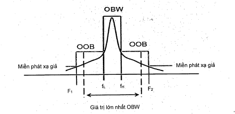
Figure 1 - Overview of the Dependency of OOB/Spurious Emission on OBW
The edge limit is defined as follows:
|
|
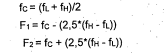
This calculation indicates the determination of the edge of the out-of-band emission region and the spurious emission region, which will be greater/less than the maximum value in the permitted operating frequency band.
2.3.4.2. Limitations
The average RMS radiated power spectral density calculated in the out-of-band region (between F1 to fL and fH to F2) must not exceed the values listed in Table 4.
Table 4 - Out-of-Band Radiation Limits
Frequency (GHz)
Average RMS Radiated Power Spectral Density (dBm/MHz)
F1 ≤ f < fL
0
fH < f ≤ F2
0
- Values fL and fH are the results of the operational frequency band measured in 2.3.1.3.
- Values F1 and F2 are calculated in 2.3.4.1.
2.3.4.3. Measurement Method
The measurement method is specified at 3.1.4.
2.3.5. Unwanted Emission in the Spurious Region
This regulation applies to all EUT.
2.3.5.1. Definition
As defined in Section 2.3.4.1.
2.3.5.2. Limitations
The effective radiated power of any spurious emission must not exceed the values listed in Table 5.
Table 5 - Spurious Emission Values
|
|

2.3.5.3. Measurement Method
The measurement method is specified at 3.1.5.
2.4. Requirements for Receivers
2.4.1. Receiver Spurious Emission
The receiver spurious emission measurement regulations apply in all modes except the transmit mode.
NOTE: On the other hand, receiver spurious emission is measured as part of the transmitter spurious emission, see 2.3.5.
2.4.1.1. Definition
Receiver spurious emission is any emission at any frequency when the device is in receive mode. Therefore, the measurement for receiver spurious emission only applies when the device can operate in receive-only mode or is a receive-only device.
2.4.1.2. Limitations
The effective radiated power of any narrowband receiver spurious emission must not exceed the values listed in Table 6.
Table 6 - Narrowband Receiver Spurious Emission Limits
|
|

Wideband receiver spurious emission must not exceed the values listed in Table 7.
Table 7 - Wideband Receiver Spurious Emission Limits
Frequency Band
Limit
Type of Separation
30 MHz – 1 GHz
-47 dBm/MHz (e.r.p.)
Peak Value
1 GHz - 300 GHz (see note)
-37 dBm/MHz (e.i.r.p.)
RMS
NOTE: The measurement only requires performing on the second harmonic of the fundamental frequency (as defined in CEPT/ERC/REC 74-01). In this case, the upper limit of the frequency range for the measurement is 154 GHz.
2.4.1.3. Measurement Method
The measurement method is specified at 3.2.1.
2.4.2. In-Band, Out-of-Band, Remote Control Signals of the Receiver
This regulation applies to all EUT.
2.4.2.1. Definition
The ability of the receiver to operate as intended when unwanted signals occur within the corresponding band, out-of-band, and at remote control bands.
2.4.2.2. Limitations
With the presence of unwanted signals defined in Table 8, the EUT will achieve the desired performance criteria (see 2.2.2).
Unwanted signals from the transmitter may continuously transmit signals at specific frequencies, as listed in Table 8.
Table 8 - Unwanted Signals for Sensors in the 76-77 GHz Band
In-Band Signal
Out-of-Band Signal
Remote Control Signal
Frequency
Center Frequency (fof) of the modulated signal of the EUT (see 2.3.1)
f = fof ± F
f = fof ± 10 x F
Field Strength of the EUT Signal
55 mV/m
173 mV/m
173 mV/m
e.i.r.p. Value at 10 m Distance
10 dBm
20 dBm
20 dBm
F: Permitted Frequency Bandwidth (1 GHz)
2.4.2.3. Measurement Method
The measurement method is specified at 3.2.2.
3. MEASUREMENT METHODS
3.1. Measurement for Transmitters
3.1.1. Operational Frequency Band
This measurement is performed under normal and harsh testing conditions.
The spectrum analyzer is set up in the receiving measurement mode as follows (see Appendix B).
a) Start Frequency: Lower edge frequency of the permitted frequency band.
b) Stop Frequency: Higher edge frequency of the permitted frequency band.
c) Resolution Bandwidth: 1 MHz.
c) Video Bandwidth: ≥ 3 MHz.
d) Detector Mode: RMS (see ITU-R SM.328-11 recommendation).
e) Display Mode: Maximum Hold.
f) Averaging Time: ≥ 1 ms per sweep point.
Approximately 99% of the OBW is used to determine the operational frequency band.
• Determine fH: fH is the frequency of the upper marker from the OBW.
• Determine fL: fL is the frequency of the lower marker from the OBW.
• Determine the central frequency fc: fc= (fH +fL)/2.
Additionally, the results recorded from the average power measurements described in 3.1.2 can be used.
3.1.2. Average Power
This measurement is performed under normal and harsh testing conditions.
There are three measurement methods used to measure average power. Each method is applied to all EUT.
3.1.2.1. Spectrum Analyzer Measurement Method
The spectrum analyzer is set up in the receiving measurement mode as follows (measurement setup described in Appendix B):
a) Start Frequency: Lower edge frequency of the permitted frequency band.
b) Stop Frequency: Higher edge frequency of the permitted frequency band.
c) Resolution Bandwidth: 1 MHz.
c) Video bandwidth (VBW): VBW ≥ RBW.
d) Detector mode: RMS.
e) Display mode: Clear write.
f) Averaging time: Greater than one cycle time of EUT.
g) Sweep time: (Averaging time) x (Number of sweep points).
The channel power is used to calculate average power. The boundaries for calculation must be determined. These boundaries are typically the operating frequency band.
3.1.2.2. Method using an average power meter
The power meter must be connected to the measurement antenna. Frequency correction factors must be included in the calculation. The power meter must be a true RMS power meter (see Appendix F, Section F.2). Measurement time must be equal to or longer than the cycle time of EUT.
3.1.2.3. Method using a peak power meter
The power meter must be connected to the measurement antenna. Frequency correction factors must be included in the calculation. The power meter must be a true peak power meter (see Appendix F, Section F.2). Measurement time must be sufficiently long compared to the cycle time of EUT.
Average power is obtained by multiplying the measured peak power with the duty cycle of the source.
Average power = (Measured peak power) x (Duty cycle of the source)
Where: Duty cycle of the source is the percentage of EUT in the On state over the total cycle time of EUT.
3.1.3. Peak Power
This measurement is performed under normal and harsh testing conditions.
There are three methods used to measure peak power. Article 3.1.3.1 (method using a spectrum analyzer): Settings depend on the frequency sweep speed of EUT. Articles 3.1.3.2 and 3.1.3.3 (methods using a power meter) do not depend on the frequency sweep speed of EUT.
3.1.3.1. Method using a spectrum analyzer
The spectrum analyzer is set up in measurement reception mode as follows (see Appendix B):
a) Start Frequency: Lower edge frequency of the permitted frequency band.
b) Stop Frequency: Higher edge frequency of the permitted frequency band.
c) Resolution bandwidth (RBW): 1 MHz with a frequency sweep rate less than 1_000 MHz/ms.
NOTE: For EUTs with higher frequency sweep rates, RBW must be increased until a stable peak power index is achieved.
c) Video bandwidth (VBW): VBW ≥ RBW.
d) Detector mode: Peak or auto peak detector mode.
e) Display Mode: Maximum Hold.
f) Averaging time: Greater than one cycle time of EUT.
g) Sweep time: (Measured average time) x (Number of sweep points).
The required peak power is the highest value recorded in the measurement results.
3.1.3.2. Method using an average power meter
The power meter must be connected to the measurement antenna. Frequency correction factors must be included in the calculation. The power meter must be a true RMS power meter (see Appendix F, Section F.2).
Measurement time must be sufficiently long compared to the cycle time of EUT.
Peak power is obtained by dividing the measured average power by the duty cycle of the source.
Peak power = (Measured average power) / (Duty cycle of the source)
Where: Duty cycle of the source is the percentage of EUT in the On state over the total cycle time of EUT.
3.1.3.3. Method using a peak power meter
The power meter must be connected to the measurement antenna. Frequency correction factors must be included in the calculation. The power meter must be a true peak power meter (see Appendix F, Section F.2).
3.1.4. Unwanted emissions outside the band
This measurement is performed under normal measurement conditions.
A spectrum analyzer is used as a receiver. The receiver bandwidth must comply with CISPR 16. To achieve the necessary sensitivity, a narrower resolution bandwidth may be required, which must be noted in the measurement results and narrowed according to A.5 of Appendix A.
In cases where EUT has multiple operating modes, only the highest peak e.i.r.p. mode (see 3.1.3) needs to be measured.
Measurements must be conducted on the out-of-band (OOB) frequency bands and the specified sub-bands as defined in 2.3.4.
a) Start frequency: See 2.3.4.2
b) Stop frequency: See 2.3.4.2
c) Resolution bandwidth:
- From 30 MHz to 1 GHz: 100 kHz.
- Above 1 GHz: 1 MHz.
c) Video Bandwidth: ≥ 3 MHz.
d) Detector mode:
- From 30 MHz to 1 GHz: Quasi-peak;
- Above 1 GHz: RMS.
e) Display mode: Clear write.
f) Averaging time: Greater than one cycle time of EUT.
g) Sweep time: (Averaging time) x (Number of sweep points).
NOTE: The number of sweep points must be greater than the spectrum analyzer's clock divided by RBW.
The spectrum measured at the spectrum analyzer is recorded within an amplitude range of approximately 35 dB. Measurement is not required when the average power spectral density is below -40 dBm/MHz (e.i.r.p.) above 1 GHz.
Measurements of average power spectral density below -40 dBm/MHz (e.i.r.p.) are not required above 1 GHz.
The measurement position is described in Appendix B, fully meeting the requirements of the specific frequency band used in the measurement. Receiver bandwidths must be set to appropriate values to accurately measure unwanted emissions. This bandwidth must be recorded in the measurement results. For frequencies above 40 GHz, a downconverter as described in Figure 2 should be used. An internal oscillator is used to reduce the received signal frequency with better than -80 dBc/Hz phase noise at 100 kHz offset. The internal oscillator frequency is selected so that the received signal after the downconverter falls within the operating frequency band of the spectrum analyzer while maintaining full IF bandwidth response to capture the entire signal spectrum.
For spurious emission measurements, an LNA (low-noise amplifier) should be used before connecting to the spectrum analyzer to achieve the necessary sensitivity.
|
|

Figure 2 - Measurement setup diagram for out-of-band radiation and spurious emissions
3.1.5. Spurious emissions
See provisions at 3.1.4 (where: Start frequency (Start frequency) and Stop frequency (Stop frequency) apply according to 2.3.5.2 when setting up the spectrum analyzer to perform this measurement).
3.2. Measurement for receivers
3.2.1. Receiver spurious emissions
This measurement is performed under normal measurement conditions.
3.2.1.1. General Provisions
Separate spurious emission measurements do not need to be performed for EUT where the receiver is located at the same position and operates simultaneously with the transmitter. In this case, the provisions at 3.1.4 will apply to spurious emissions and out-of-band emissions.
In all other cases, the following applies:
a) Measurement positions as described in Appendix B must meet the requirements of the specific frequency band used for measurement. The measurement antenna must be initially oriented vertically polarized and connected to the receiver. The receiver must be a spectrum analyzer with settings as specified in 3.1.4.
The receiver must be placed on a stand at its standard position.
b) The frequency of the receiver must be adjusted within the range defined in the relevant harmonized standard. The frequency of each component of the test signal must be noted. If the measurement position is interfered with by external radiation, this qualitative value can be obtained in a shielded room with reduced distance between the transmitter and the measurement antenna.
c) At each frequency where a component has been detected, the receiver must be adjusted and the measurement antenna must be raised or lowered through the specified height range until the maximum signal level is observed on the receiver.
d) The receiver must be rotated up to 360° around the vertical axis to obtain the maximum signal level.
e) The measurement antenna must be raised or lowered again within the specified height range until the maximum level is obtained. This level will be recorded.
f) A substitute antenna will replace the receiving antenna at the same position and in the vertically polarized direction. It will be connected to the signal generator.
g) At each frequency where a component has been detected, the signal generator, substitute antenna, and receiver must be adjusted. The test antenna must be raised or lowered within the specified height range until the maximum signal level is observed on the receiver. The value provided by the signal generator gives the equivalent signal value on the receiver as in step e). After adjusting the gain of the substitute antenna and cable loss, this value is the spurious emission component at that frequency.
h) The frequency and value of each spurious emission measured and the receiver bandwidth will be recorded in the measurement results.
i) The measurements from b) to h) must be repeated with the measurement antenna oriented horizontally polarized.
3.2.1.2. Measurement
To measure spurious emissions, the spectrum analyzer is set to receive measurement mode as follows:
a) Resolution bandwidth (Resolution bandwidth): 100 kHz.
c) Video bandwidth (Video bandwidth): 100 kHz.
d) Detector mode (Detector mode): Positive peak mode.
e) Averaging (Averaging): Off.
f) Span (Span): 100 MHz.
g) Sweep time (Sweep time): 1 s.
h) Amplitude (Amplitude): Adjusted to the middle of the amplitude range.
For measuring emissions exceeding 6 dB below the specified limit, the resolution bandwidth will be switched to 30 kHz and the span will be adjusted accordingly. If the level does not change more than 2 dB, it is a narrowband emission; the observed value must be recorded in the measurement results. If the level changes more than 2 dB, it is a wideband emission and the observed value must be recorded in the measurement results.
If the wideband emission measurement method is applied, it must be recorded in the measurement results.
NOTE: The main spectrum of the device under test may saturate the input circuits of the spectrum analyzer and thus cause a "spurious emission" ghost signal. A "spurious emission" ghost signal can be distinguished from a real signal by increasing the input attenuation by 10 dB. If the false signal disappears, it is a "spurious emission" ghost signal and should be disregarded.
3.2.2. In-band, out-of-band, remote control signals of the receiver
This measurement is performed under normal measurement conditions.
3.2.2.1. Introduction
Section 3.2.2.1 sets out the measurement methods for testing the EUT's ability to handle unwanted signals when operating in normal mode.
3.2.2.2. Measurement Setup
The target type (RCS), position, and distance related to the EUT are determined in the relevant harmonized standard. The unwanted signal source is placed within the 3 dB bandwidth at the central operating frequency of the RX. See 3.2.2.4 for unwanted signal parameters.
The desired implementation criteria are set forth in the relevant harmonized standard.
3.2.2.3. Measurement Procedure
• The target and unwanted signal source must be defined as specified in 3.2.2.2.
• The EUT will be ACTIVATED. The completion of the desired performance criteria will be verified.
• The unwanted signal source must be ACTIVATED at a level 20 dB below the unwanted signal level specified in 3.2.2.4.
• To simulate practical usage scenarios, the unwanted signal level will be increased in 5 dB steps until the desired performance criteria are not met or the unwanted signal level indicated in 3.2.2.4 is reached. The unwanted signal must be held at each step source for at least 5 seconds. The measurement process must be repeated for each frequency band of the unwanted signal source as defined in 3.2.2.4.
3.2.2.4. Unwanted Signal Specifications
The unwanted signal transmitter may transmit signals at specific frequencies as described in the relevant harmonized standards.
5. RESPONSIBILITIES OF ORGANIZATIONS AND INDIVIDUALS
4.1. Radar devices operating in the 76 GHz to 77 GHz frequency range, as regulated under Article 1.1, must comply with the provisions of this standard.
4.2. The testing for technical requirements of this standard for declaration of conformity must be conducted in accordance with current regulations. Organizations and individuals may use test results from laboratories recognized as compliant with ISO/IEC 17025 or manufacturer test results to declare conformity.
5. RESPONSIBILITIES OF ORGANIZATIONS AND INDIVIDUALS
Relevant organizations and individuals are responsible for declaring conformity for devices within the scope of this standard and are subject to state management authority inspections according to current regulations.
6. IMPLEMENTATION ORGANIZATION
6.1. The Telecommunications Authority, the Radio Frequency Management Agency, and Provincial Information and Communications Departments are responsible for implementing guidance and managing devices within the scope of this standard.
6.2. In cases where provisions of this standard are changed, supplemented, or replaced, they shall be implemented according to the new document.
6.3. During the implementation of this standard, if issues arise, organizations and individuals should report them in writing to the Ministry of Information and Communications (Science and Technology Department) for guidance and resolution./.
ANNEX A
Product Name, Goods According to QCVN
General Conditions
A.1. Overview
This section provides all general provisions for short-range radar device testing. These provisions and requirements relate to the arrangement of the device to be tested (see A.2), requirements for the EUT (see A.3), general testing conditions (see A.4), reference bandwidths for measurements (see A.5), explanation of test results (see A.6), and test results (see A.7).
A.2. Device Information
The following device information may be necessary for testing and must be provided by the manufacturer, such as:
• Environmental conditions and relevant harmonized standards;
• Supply voltage for the radio equipment or supply voltage for the main equipment or combined equipment in case the radio equipment is attached;
• Type of technology/modulation used in the device (e.g., pulse, Doppler pulse, FMCW, etc.);
• For all modulation schemes, modulation parameters must be provided: e.g., modulation time, pulse sweep time, modulation bandwidth;
• High and low power modes;
• Equipment power cycle;
• Operating frequency range of the device (see 3.1.1);
• Typical orientation of the EUT;
• Antenna polarization for both transmitting and receiving antennas;
• Antenna radiation pattern, as well as antenna width, horizontal and vertical 3 dB points for both transmitting and receiving antennas;
• Details of any antenna switching or electronic/mechanical scanning. When such features exist, information on whether they can be disabled for testing purposes must also be clarified;
• Desired temperature range, including the required startup time of the EUT (see A.4.4.1.2.);
• Information about the device functions to establish desired performance criteria (see 3.2.2).
A.3. Requirements for the EUT
A.3.1. EUT Version and Configuration
Testing may be performed on production devices or equivalent versions of the device.
NOTE: The manufacturer is responsible for ensuring that the device put into service meets the relevant current legal requirements, including RE-D.
If a device has optional features considered not directly affecting RF parameters, measurements only need to be performed on the device configured with the worst-case combination of features published by the manufacturer.
A.3.2. Presentation
The manufacturer will provide all necessary means to operate the EUT throughout the testing process.
A.3.3. Multiple Operating Bandwidths
All operating bandwidths of the device must be published by the equipment manufacturer (see A.2).
When the equipment has multiple operating bandwidths, a sufficient number of operating bandwidths must be selected for testing, including the lower and higher frequency limits, minimum and maximum bandwidths.
A.3.4. Modulation Requirements During Testing
The production of the EUT during the measurement process must ensure the normal operation of the equipment. The manufacturer must use the operating mode of the equipment to make the transmitter operate at its highest capacity, suitable for the requirement of measuring the highest power transmission level that will occur during operation, and must ensure that:
• Continuous transmission throughout the measurement period;
• The transmission sequence can be accurately repeated. For transmitters with multiple combined multi-modulation schemes, each scheme must be checked individually.
A.3.5. Requirements when the EUT uses scanning antennas
A.3.5.1. Classification
Within the scope of this standard, the EUT is divided into three types according to the type of transmitting antenna:
• Fixed beam: In this type of EUT, the antenna radiation pattern is unchanged and the direction of transmission is fixed corresponding to the housing of the EUT.
• Constant model: In this type of EUT, the antenna radiation pattern is unchanged and the direction of transmission changes over time. The scanning speed of the transmission direction is fixed.
• Variable model: This type of EUT includes all types that are not fixed model or constant model types. The antenna radiation pattern changes over time and/or direction or the scanning process occurs at varying speeds. For classification purposes, if it remains fixed and unchanged within 1 degree or 1%, it is considered normal operation.
NOTE 1: The classification depends solely on the type of transmitting antenna.
NOTE 2: Generally, mechanically scanned antennas will be constant models and electrically scanned antennas will be variable models.
NOTE 3: Although the terms beam and model are used infrequently, the considerations and classifications apply equally to EUTs with multiple beams.
A.3.5.2. Measurement of fixed beam EUT
No special considerations are applied. Measurements must be performed on the direction achieving maximum gain of the antenna unless otherwise specified.
A.3.5.3. Measurement of constant model EUT
Scanning may be obstructed and measurements are performed on the transmitted beam unless otherwise specified. The parameters of the EUT operating in normal mode can be calculated based on knowledge of the antenna. The manufacturer must publish the relevant antenna parameters.
A.3.5.4. Measurement of variable model EUT
Measurements must be performed with a scanning antenna. A set of measurements may need to be conducted across the entire sphere or hemisphere. For radiated energy measurements (e.g., peak power, average power, duty cycle), the direction chosen is the one yielding the highest result.
A.4. Measurement Conditions
A.4.1. Introduction
Measurements must be carried out under normal measurement conditions. For certain requirements, harsh measurement conditions may need to be used.
The conditions and procedures for measurement must be conducted as specified in Sections A.4.2 to A.4.4.
A.4.2. Power Supply
During testing, the device's power supply must be replaced with a test power supply capable of generating the normal test voltage as specified in A.4.3.2 and the harsh test voltage as specified in A.4.4.2. The internal impedance of the test power supply must be low enough to have negligible impact on the test results. For testing purposes, the power supply voltage must be measured at the device inputs.
For devices powered by batteries, the battery may be removed and the test energy source applied as close to the battery terminals as possible.
During measurements, the power supply voltage must be maintained within a tolerance of ±1% of the voltage at the start of each test. This tolerance value is critical for power measurements; using a smaller tolerance will provide better measurement uncertainty values.
A.4.3. Normal Measurement Conditions
A.4.3.1. Normal Temperature and Humidity
The normal temperature and humidity conditions for testing must be a suitable combination of temperature and humidity within the following ranges:
Temperature: +15 °C to +35 °C;
Relative humidity: 20% to 75%.
If measurements cannot be performed under these conditions, the ambient temperature and relative humidity during the measurements must be noted and recorded in the test results.
Actual values from the measurements must be recorded in the test results.
A.4.3.2. Normal Power Supply
A.4.3.2.1. Power Supply Voltage
The power supply voltage connected to the device under test must be the rated voltage. Within the scope of this standard, the rated voltage is the voltage for which the device is designed to operate.
The frequency of the test power supply voltage for alternating current (AC) must be within the range of 49 Hz to 51 Hz.
A.4.3.2.2. Lead-Acid Battery Power Supply Used in Vehicles
When the radio device is designed to operate normally from a lead-acid battery power supply used in vehicles, the normal test power supply voltage must be 1.1 times the rated voltage of the battery (6 V, 12 V, etc.).
A.4.3.2.3. Other Power Supplies
If the device under test uses other power supplies or types of batteries (primary or secondary), the rated test power supply voltage published by the manufacturer must be recorded in the test results.
A.4.4. Harsh Measurement Conditions
A.4.4.1. Harsh Temperature
A.4.4.1.1. Testing Procedure at Harsh Temperatures
Before performing measurements, the device must reach thermal equilibrium in the test room. The device must not be turned off during the thermal stabilization period.
If thermal equilibrium is not verified through measurements, the minimum thermal stabilization time must be one hour, or the duration may be determined by an accredited test facility. The measurement sequence must be selected, and the humidity in the test room must be controlled to prevent excessive condensation.
A.4.4.1.2. Harsh Temperature Range
For measurements at harsh temperatures, the measurements must be performed according to the procedures specified in Appendix B, at the upper and lower temperatures of one of the following ranges as specified by the manufacturer:
Type I temperature: -10 °C to +55 °C.
Type II temperature: -20 °C to +60 °C.
Type III temperature: -40 °C to +70 °C.
The manufacturer may specify a wider temperature range than the minimum above. The test results must state the temperature range used.
A.4.4.2. Harshness Test Supply Voltage
A.4.4.2.1. Main Voltage
The harshness test voltages for equipment connected to the main AC supply must be the nominal voltage with a tolerance of ± 10 %.
A.4.4.2.2. Other Power Sources
For equipment using other power sources, or capable of operating from multiple different power sources, the harshness test voltage must be the voltage published by the manufacturer. These must be recorded in the test results.
A.5. Reference Bandwidth of the Measuring Receiver
Generally, the resolving bandwidth (RBW) of the measuring receiver must be equal to the reference bandwidth (RBW) specified in Table A.1.REFTable A.1 – Reference Bandwidth of the Measuring Receiver
Frequency Range (f)
Resolving Bandwidth of the Measuring Receiver (RBW)
30 MHz ≤ f ≤ 1,000 MHzREF)
100 kHz
f > 1,000 MHz
NOTE: The frequency range and corresponding RBW values are obtained from CISPR 16.
2.2. Measurement Methods
To improve measurement accuracy, sensitivity, and efficiency, RBW may differ from RBWREF . When RBW
measuredREF< RBW, the result will be integrated over RBW , for example according to formula (1):REF- P(i) is the measured samples with RBWREF - n is the number of samples within RBW
(1)
Where:
REFMEASURED;
is the corresponding value at RBWWhen RBW;
- PCORR > RBWREF.
, the result for wideband emissions will be normalized according to the bandwidth ratio according to formula (2)., the result will be integrated over RBW CORPREF+ 10 log (RBW
"5. The pre-tax weighted average cost of capital i (%) is determined according to the formula below:ref x TMEASURED /RBWis the value measured at a wider bandwidth than RBWFor discrete emissions determined at a narrow peak with at least 6 dB above the average level within the measurement bandwidth, the correction on RBWMEASURED) (2)
Where:
- PMEASURED is not applied while integration over RBWMEASURED;
- PCORR > RBWREF.
is still used.REF A.6. Explanation of Measurement Results and Permissible Measurement Uncertainty
A.6.1. Overview
The explanation of the results for measurements described in this standard is as follows:
1) The measured value related to the corresponding limit will be used to determine whether the equipment meets the requirements of this standard;
2) The permissible measurement uncertainty for each parameter must be recorded in the test results;
3) The value of the measurement uncertainty must be recorded at any position, for each measurement, equal to or lower than the figures in Table A.2, and the procedure specified in A.6.3 must be used.
For the measurement methods in this standard, the figures for measurement uncertainty must be calculated according to the guidance provided in ETSI TR 100 028 and will correspond to the expansion factor (coverage factor) k = 1.96 or k = 2 (providing a confidence level of 95 % and 95.45 % respectively in the case where the distribution characterizing the measurement uncertainty is normal (Gaussian distribution)).
Table A.2 is based on such expansion factors.
Table A.2 - Maximum Permissible Measurement Uncertainty
Measurement Uncertainty
Parameter
±1 x 10
Radio Frequency
All emissions, radiation-5
±6 dB
±1 °C
Salinity
DC voltage and low-frequency voltage
Moisture content
±5 %
A.6.2. Maximum Permissible Measurement Uncertainty
±3 %
In cases where the measurement uncertainty exceeds the limits in Table A.2, the provisions of A.6.4 shall apply.
A.6.3. Measurement Uncertainty Equal to or Less Than the Maximum Permissible Uncertainty
The explanation of the results when comparing measured values with technical specification limits will be as follows:
a) When the measured value does not exceed the limit value, the equipment under test complies with the relevant harmonized standard requirements.
b) When the measured value exceeds the limit value, the equipment under test does not comply with the relevant harmonized standard requirements.
c) The measurement uncertainty calculated by the testing technician performing the measurement must be recorded in the test results.
d) The measurement uncertainty calculated by the testing technician may be the maximum value in a range of measured values or may be the permissible measurement uncertainty for a specific measurement that has not been performed. The method used must be recorded in the test results.
A.6.4. Measurement Uncertainty Greater Than the Maximum Permissible Uncertainty
The explanation of the results when comparing measured values with technical limits will be as follows:
a) When the measured value plus the difference between the measurement uncertainty calculated by the testing technician and the maximum permissible measurement uncertainty does not exceed the limit value, the tested equipment complies with the relevant harmonized standard requirements.
b) When the measured value plus the difference between the measurement uncertainty calculated by the testing technician and the maximum permissible measurement uncertainty exceeds the limit value, the tested equipment does not comply with the relevant harmonized standard requirements.
A.7. Test Results
d) The measurement uncertainty calculated by the testing technician may be the maximum value in a range of measured values or may be the permissible measurement uncertainty for a specific measurement that has not been performed. The method used must be recorded in the test results.
A.6.4. Measurement Uncertainty Greater Than the Maximum Permissible Uncertainty
The test results must contain all necessary and relevant information to evaluate compliance with the essential requirements listed in Appendix A of the relevant harmonized standard (see ETSI EN 301 091-1, ETSI EN 301 091-2, ETSI EN 301 091-3, ETSI EN 302 264, and ETSI EN 302 858).
Setup of the Measurement and Measurement Procedure
Provisions on the HS Code of Terrestrial Mobile Radio Equipment and Terrestrial Radio Relay Equipment
Product Name, Goods According to QCVN
B.1. Introduction
Generally, there is a difference between performing conducted measurements and radiated RF measurements. However, for the EUTs mentioned in this standard, it should be noted that no RF conducted measurements are performed.
Below, the general setup of the test environment for the radiated measurement of short-range radar devices will be described.
B.2. Initial Measurement Steps
The measurement process must be planned using the information provided by the manufacturer (see A.2 of Appendix A).
The settings of the measuring receiver must be chosen based on the signal description provided, to ensure that the highest values of peak power and average PSD are captured. This is particularly important for frequency scanning receivers (spectrum analyzers) and signals that vary over time and/or frequency and/or direction. It is recommended that the initial signal be observed in both peak and average modes across its full bandwidth to confirm the description and set up where the highest values occur. This will allow subsequent measurements to be made with narrower RF. In cases of any doubt about the impact of frequency scanning, a measurement at a single RF (zero beat) will provide confirmation of this.
B.3. Radiation Measurements
B.3.1. Overview
B.3.1. Overview
The measurement area, test antennas, and spare antennas used for radiation measurements must be described as set out in Appendix C. For guidance on using radiation measurement positions, see B.3.2. For guidance on standard measurement positions used for radiation measurements, see Appendix D.
All efforts should be made to clearly demonstrate that the emission from the EUT transmitter does not exceed the specified limit, with the transmitter in the far field. Within the scope of what can be practically achieved, the radio equipment under test must be measured at the distance specified in B.3.2.4 and with the specific bandwidth. However, to obtain an appropriate signal-to-noise ratio in the measurement system, radiation measurements may have to be performed at distances smaller than those specified in B.3.2.4 and/or reduce the measurement bandwidths. Any modified measurement configuration must be indicated in the test results, along with a note explaining why the relevant signal levels associated with the measurement at the used distance or with the used measurement bandwidth were detected accurately by the measuring equipment and the calculation proving compliance.
In cases where the measurement bandwidth cannot be further reduced (due to limitations of the measuring equipment typically available or difficulties in converting the readings taken using a measurement bandwidth to the bandwidths used by the limits set forth in the relevant harmonized standard), the measurement results will specify this fact, the measurement distance and bandwidth used, the near field/far field range established for the measurement, the emissions of the radio equipment being measured, the background noise that could be achieved, and the relevant frequency band.
B.3.2. Guidance on Using the Radiation Measurement Area
B.3.2.1. Introduction
This section details the procedures, equipment setup, and verifications that must be carried out before conducting any radiation measurements.
B.3.2.2. Measurement Area Verification
Measurements should not be conducted in an area without valid certification. The verification procedures for different types of measurement areas (i.e., non-reflective measurement rooms and non-reflective measurement rooms with a ground plane) are described in Appendix C and are provided in the relevant sections of ETSI TR 102 273 or equivalent.
B.3.2.3. Mounting Bracket
When necessary, there must be a mounting bracket of sufficient size to mount the EUT on a turntable. This support must be constructed from low-conductivity material, with a relative dielectric constant of less than 1.5 (such as expanded polystyrene, soft wood, etc.).
B.3.2.4. Distance Range
The distance range for all types of measurement equipment must be sufficient to allow measurements in the far field of the EUT, i.e., it must be equal to or greater than:
Where:
- d1 is the largest dimension of the EUT/dipole after replacement (m);
- d2 is the largest dimension of the measurement antenna (m);
- λ is the wavelength of the measurement frequency (m).
This formula ensures that the error due to near-field effects exceeds 0.25 dB on the antenna's main beam direction, which may be required to measure the antenna radiation pattern accurately. However, such high accuracy is not necessary for compliance purposes.
Additionally, for mm-waves, the resulting distance may be so large that the measured power approaches the sensitivity level of the detector and/or room measurements become impractical. Therefore, the following reduced far-field distances are considered.
Table B.1 - Far Field Measurement Distance
Far Field Distance
Near-Field Power Error Level
(due to near-field effects)
For coal-fired thermal power plants where the enterprise holds 100% of the registered capital and uses 100% of its own capital to invest in the project approved by the competent authority, E is determined as 100%;FF
0.25 dB
For coal-fired thermal power plants where the enterprise holds 100% of the registered capital and uses 100% of its own capital to invest in the project approved by the competent authority, E is determined as 100%;FF/2
0.9 dB
For coal-fired thermal power plants where the enterprise holds 100% of the registered capital and uses 100% of its own capital to invest in the project approved by the competent authority, E is determined as 100%;FF/3
2 dB
For coal-fired thermal power plants where the enterprise holds 100% of the registered capital and uses 100% of its own capital to invest in the project approved by the competent authority, E is determined as 100%;FF/4
3.5 dB
It should be noted in the measurement results that these conditions are met so that any additional measurement uncertainty can be included in the results.
NOTE 1: For a fully non-reflective measurement room, none of the EUT, at any angle of rotation of the turntable, lies outside the "quiet zone" of the measurement room at the designated test frequency.
NOTE 2: "Quiet Zone" is a volume within a non-reflective room (without a ground plane) in which the specified performance has been proven by measurement or guaranteed by the designer/manufacturer. The specified performance is usually the reflection coefficient of the absorber panels or a directly related parameter (e.g., amplitude and phase signal uniformity). However, it should be noted that the defined quiet zone levels tend to vary.
B.3.2.5. Preparation of the Measurement Site
Cables for both ends of the measurement area must be oriented horizontally from the measurement area at a minimum of 2 m and then allowed to hang vertically and extend through the ground plane or screen (if applicable) to the measurement equipment. Measures should be taken to minimize absorption on these cables (e.g., coating with ferrite beads or other loads). The orientation and sheath of the cables must match the tested setup.
Calibration data for all items of the measurement equipment must be available and valid. For measurements, replacement antennas, and measurement antennas, the data must include the isotropic radiated power gain (or antenna factor) for the measurement frequency. Additionally, the VSWR of the replacement antenna and the measurement antenna must be known.
Calibration data for all cables and attenuators must include loss and VSWR over the entire frequency range of the tests. All loss and VSWR figures must be recorded in the test result log for the specific test.
When calibration factors/tables are required, they must be immediately available. For all items of the measurement equipment, the maximum measurement uncertainty that they exhibit must be known along with the distribution of measurement uncertainty.
At the start of the measurement, the system should be checked on the items of equipment used in the measurement area.
B.3.3. Standard Measurement Methods
Two methods - the calibration method and the substitution method - for determining the radiated power of radio equipment are described respectively in D.1 and D.2 of Appendix D.
The standard calibration method is also described in Appendix E.
B.4. Testing Equipment Connected to a Host
For radar equipment that needs to be connected or integrated with host equipment to provide functionality for the radar, multiple alternative measurement methods are allowed.
When there are more than one such combination, the measurement will not be repeated for the combination of the radar device and multiple similar basic main devices.
When there are more than one such combination and the combinations are different, each combination must be measured for all requirements in this standard, and all separate different combinations will only be measured for spurious emission radiation (see 3.4).
NOTE: For further information on the above issue, see ETSI TR 102 070-2.
Annex C
Product Name, Goods According to QCVN
Measurement areas and general layout for measurements related to the use of radiation fields
C.1. Introduction
This section introduces the measurement area that can be used for radiation measurements. The measurement area is commonly referred to as a free-field measurement area. Both absolute and relative measurements can be performed in these areas. The measurement room must be calibrated before performing absolute measurements. Detailed calibration procedures are described in ETSI TS 102 321.
C.2. Non-reflective Measurement Room
A non-reflective measurement room is a measurement position often used to measure radiation according to this standard at frequencies above 1 GHz. However, a non-reflective measurement room with a ground plane as described in C.2 may be used at frequencies above 1 GHz provided that suitable non-reflective material is placed on the floor of the measurement room to eliminate any reflected signals. A non-reflective measurement room is a shielded room typically covered, where the inner surfaces of the walls, ceiling, and floor are coated with a layer of radio wave absorber material, usually a type of pyramidal foam urethane. Typically, the room includes an antenna stand at one end and a turntable at the other end. A typical non-reflective measurement room is illustrated in Figure C.1.
Figure C.1 - Typical Non-Reflective Measurement Room
Shielding the measurement room combined with the use of radio wave absorber material creates a controllable environment during the measurement process. This type of measurement room attempts to simulate the best conditions in free space. Shielding reduces interference from surrounding signals and external effects, while the radio wave absorber material minimizes unwanted reflections from the walls, floor, and ceiling, which could affect the measurement.
In fact, it is easy to shield to eliminate high-level surrounding interference (80 dB to 140 dB). Usually, making the surrounding interference negligible.
A turntable capable of rotating 360° in the horizontal plane is used to support the EUT at an appropriate height (for example, 1 m) above the ground plane. The measurement room must be large enough to allow measurements in the far field of the EUT. Additional information on far-field measurement requirements is provided in Section B.3.2.4 of Appendix B.
Generally, a non-reflective measurement room has many advantages over other measurement rooms. It is less affected by surrounding interference, has fewer reflections from walls, ceiling, and floor, and is independent of weather conditions. However, it also has some disadvantages, such as limited measurement distance and limitations when used at low frequencies due to the size of pyramidal absorber materials. To improve performance at low frequencies, a combination of ferrite brick structure and foam urethane absorber is often used.
All emission measurements can be performed in a non-reflective measurement room without any restrictions.
C.3. Non-Reflective Measurement Room with Ground Plane
A non-reflective measurement room with a ground plane must be used to measure radiation according to this standard at frequencies below 1 GHz. A non-reflective measurement room is a shielded room typically covered, where the inner surfaces of the walls, ceiling are coated with a layer of radio wave absorber material, usually a type of pyramidal foam urethane. The floor of the measurement room is made of bare metal (uncovered) and is flat.
Typically, the measurement room includes an antenna column at one end and a turntable at the other end. A typical non-reflective measurement room with a ground plane is shown in Figure C.2.
Figure C.2 - Typical Non-Reflective Measurement Room with Ground Plane
This type of measurement room attempts to simulate an outdoor measurement position characterized primarily by an ideal ground plane extended infinitely.
The antenna column provides variable height (from 1 m to 4 m) to optimize the position of the measurement antenna between the signal and the antenna or between the EUT and the measurement antenna.
A turntable capable of rotating 360° in the horizontal plane is used to support the EUT at a specified height, usually 1.5 m above the ground plane. The measurement room must be large enough to allow measurements in the far field of the EUT. Additional information on far-field measurement requirements is provided in Section B.3.2.4 of Appendix B.
First, the electromagnetic field emission "peak" from the EUT is measured by raising and lowering the receiving antenna on the column (to obtain maximum interference of the direct signal and the reflected signal from the EUT) and then rotating the turntable to achieve the "peak" in the azimuth plane. At this height of the measurement antenna column, the amplitude of the received signal is recorded.
Second, the EUT is replaced by a substitute antenna (placed at the phase center or power center of the EUT), connected to a signal generator. The signal is again "peaked," and the output of the signal generator is adjusted until the value obtained matches the recorded value in the first stage, and is re-measured on the radio receiver.
The sensitivity test of the receiver on the ground plane also involves reaching the peak of the electromagnetic field by raising and lowering the receiving antenna on a pole to obtain the maximum interference pattern of the direct signal and the reflected signal from the EUT. In this phase, the center of the measuring antenna is placed at the phase center or amplitude center of the EUT during the testing process. A conversion factor is provided. The measurement antenna remains at the same height as in Phase Two, where the measured antenna is replaced with the EUT. The amplitude of the transmitted signal is reduced to determine the field strength level with specific responses obtained from the EUT.
C.4. Harsh Testing Conditions
C.4.1. Radio-transparent Temperature Chamber
A temperature chamber equipped with radio-transparent doors or walls can be used for radiation measurements. The measurement procedure in this case will be similar to that under normal conditions.
The EUT will be placed on a radio-transparent support stand. The distance between the test antenna and the EUT must comply with the requirements set out in Section B.3.2.4 of Appendix B. Figure C.3 illustrates the measurement setup.
Figure C.3 - Harsh Testing Condition Setup
C.4.2. Use of Fixed Test Equipment
C.4.2.1. Overview
Fixed test equipment may be used to facilitate measurements under harsh conditions.
C.4.2.2. Characteristics
The fixed test equipment is a radio device that integrates the EUT's built-in antenna with a 50 Ω RF terminal at the frequency at which the measurements need to be performed.
The fixed test equipment must be fully described.
Additionally, the fixed test equipment shall provide:
a) Connection to external power supply;
b) A method to provide input or output from the equipment. This may include coupling to or from the antenna. The fixed test equipment may also provide appropriate coupling means, such as for data or video output.
Fixed test equipment is typically supplied by the manufacturer.
The performance characteristics of the fixed test equipment must be approved by the testing laboratory and must meet the following basic parameters:
a) Coupling loss not greater than 30 dB;
b) Suitable bandwidth characteristic;
c) Change in coupling loss across the frequency band used for measurement not exceeding 2 dB;
d) The connection circuit with RF coupling contains passive or nonlinear devices;
e) VSWR at the 50 Ω port not greater than 1.5 over the measurement frequency band;
f) Coupling loss must be independent of the position of the fixed test equipment and not affected by nearby objects or people. The coupling loss must be reproducible when the equipment is removed and replaced. Typically, the fixed test equipment is positioned in a fixed location and provides a fixed position for the EUT;
g) Coupling loss remains unchanged when environmental conditions change.
The coupling loss of the fixed test equipment may have a maximum noise contribution from the test equipment of +10 dB. If the coupling loss is too high, an external linear LNA may be used.
Figure C.4 - Fixed Test Equipment
The field probe (or small antenna) needs to be terminated reasonably.
The characteristics and confirmation will be stated in the test results.
C.4.2.3. Confirmation of Fixed Test Equipment in a Temperature Chamber
The fixed test equipment is placed in a temperature chamber (only necessary if fixed test equipment measurements are conducted under harsh temperature conditions).
. Annually, based on the progress of plan formulation, the Departments of Science and Technology refer to the Program's objectives and content and criteria for selecting projects for each region, advise the People's Committee of provinces and cities on the goals, content, scope, and scale of projects within the Program's scope to be included in the annual science and technology plan of the province or city. After discussing the annual plan with relevant departments and agencies at the local level, the project is refined and supplemented to seek the opinion of the provincial or municipal Science and Technology Council.
A transmitting antenna connected to a signal generator must be placed at a far-field distance not less than one λ from the fixed test equipment at that frequency. The fixed test equipment includes mechanical support for the EUT, antenna, or field probe, and a 50 Ω termination load for the field probe. The fixed test equipment must be connected to the spectrum analyzer through a 50 Ω connector. The signal generator must be set to the EUT's nominal frequency (see Figure C.5). The unmodulated signal output power from the signal generator must be set to a value sufficiently high to be observable by the spectrum analyzer. This reference value must be recorded in the test results. The signal generator is then set to the upper and lower limits of the EUT's defined frequency band. The measured values should not deviate more than 1 dB from the value at the nominal frequency.
Figure C.5 - Confirmation of Fixed Test Equipment Without EUT
Step 2
During confirmation and testing, the EUT must be attached to the fixed test equipment in the off state, see Figure C.6. The measurements in Step 1 will be repeated, this time with the EUT in place. The measured values are compared to those in Step 1 and should not change more than 2 dB. This ensures that the EUT does not significantly reduce the radiated power.
Figure C.6 - Confirmation of Fixed Test Equipment With EUT in Place
C.4.2.4. Use of Fixed Test Equipment for Measurement in a Temperature Chamber
Here, the signal generator and transmitting antenna are removed. The EUT is powered via an external DC power supply (see Figure C.7). In cases where the EUT operates on batteries, temporarily supplied by an external power source as well as temporary control signal paths, a coupling filter must be added directly at the EUT to avoid parasitic effects and electromagnetic radiation.
At the 50 Ω port of the fixed test equipment, a measuring receiver is connected to record the relevant parameters.
Figure C.7 - Measurement of EUT Conducted in a Temperature Chamber
C.5. Test Antenna
C.5.1. Overview
A test antenna is always used in radiation testing methods. In emission measurements (that is: effective radiated power, spurious emissions), the test antenna is used to detect the field from the EUT in one measurement phase and from a substitute antenna in another phase. When the test area is used to measure receiver characteristics (that is, sensitivity and other immunity parameters), the antenna is used as a transmitter radio device.
Test antennas must be mounted on a support that allows the antenna to be used in either horizontal or vertical polarization, and at measurement positions above ground plane surfaces (i.e., non-reflective measurement rooms) should allow the height relative to its center from the ground to be adjusted within the specified range (typically 1 m to 4 m).
In the frequency band from 30 MHz to 1 000 MHz, dual-polarized antennas (manufactured according to ANSI C63.5) are usually recommended. For frequencies 80 MHz and above, the radiating surfaces of the dual-polarized antennas must have lengths for resonance at the test frequency. For frequencies below 80 MHz, it is recommended to shorten the length of the radiating surface. However, for false emission measurements, a combination of symmetrical antennas and periodic dual-polarized arrays (commonly referred to as "log periodic") may be used to cover the entire frequency band from 30 MHz to 1 000 MHz. Above 1 000 MHz, horn antennas are recommended, with directional gain, and log periodic arrays may also be used.
NOTE: The gain of horn antennas is typically described in relation to an isotropic radiator.
C.5.2 Substitute Antennas
Substitute antennas are used to replace the EUT for transmission parameter measurements (that is: frequency error, effective radiated power, false emissions, and adjacent channel power). For measurements in the frequency band from 30 MHz to 1 000 MHz, substitute antennas must be dual-polarized antennas (manufactured according to ANSI C63.5). For frequencies 80 MHz and above, the radiating surfaces of the dual-polarized antennas must have lengths for resonance at the test frequency. For frequencies below 80 MHz, it is recommended to shorten the length of the radiating surface. For measurements above 1 000 MHz, standard gain horn antennas are recommended.
C.5.3 Measurement Antennas
Measurement antennas are used in tests on the EUT for reception parameters (that is: sensitivity and other immunity measurements) being measured. The purpose is to measure the electric field strength in the vicinity of the EUT.
For measurements in the frequency band from 30 MHz to 1 000 MHz, measurement antennas must be dual-polarized antennas (manufactured according to ANSI C63.5). For frequencies 80 MHz and above, the radiating surfaces of the dual-polarized antennas must have lengths for resonance at the test frequency. For frequencies below 80 MHz, it is recommended to shorten the length of the radiating surface. For measurements above 1 000 MHz, standard gain horn antennas are recommended. The center of this antenna should coincide with the phase center or amplitude center (as specified in the test method) of the EUT.
Appendix D
Product Name, Goods According to QCVN
Standard Measurement Methods
D.1 Calibration Setup Using Rx Link Calculation
The receiver, test antenna, and all related equipment (e.g., cables, filters, amplifiers...) must be calibrated according to known standards at all frequencies where device measurements are performed. A suggested calibration method is provided in Appendix E.
If a non-reflective measurement room with a ground plane is used, the floor must be covered with absorptive material in the area directly reflecting from the EUT to the test antenna.
Equipment must be placed in a non-reflective measurement room (see Appendix C), allowing spherical evaluation of the equipment. The EUT must be positioned as close as possible to its normal operating direction.
The test antenna must be initially oriented for vertical polarization and must be selected to match the frequency of the transmitter.
The output of the test antenna must be connected to the spectrum analyzer through any required equipment (fully characterized) to display measurable signals (e.g., amplifier).
The EUT must be turned on in unmodulated mode (if possible), and the spectrum analyzer must be tuned to the frequency of the transmitter during testing.
The test antenna must be raised and lowered within the specified height range until the maximum signal level appears on the spectrum analyzer. Alternatively, the EUT can be tilted within a suitable range.
The EUT will then be rotated 360° in the horizontal plane until the maximum signal level appears on the spectrum analyzer. Alternatively, the test antenna can be rotated around the EUT.
The test antenna must be raised and lowered again within the specified height range until the maximum signal level appears on the spectrum analyzer. Alternatively, the EUT can be tilted within a suitable range.
The measurement must be repeated with the test antenna oriented for horizontal polarization.
The maximum signal level detected by the spectrum analyzer must be recorded and converted to radiated power by applying pre-determined calibration factors for the equipment configuration used.
D.2 Calibration Setup Using Substitution Method
On the measurement area specified in Appendix C, the equipment must be placed at the specified height on a stand as defined in Appendix C and in the position closest to its normal use as published by the manufacturer.
The test antenna must be initially oriented for vertical polarization and must be selected to correspond to the frequency of the transmitter.
The output of the test antenna must be connected to the spectrum analyzer.
The EUT must be turned on in unmodulated mode (if possible), and the spectrum analyzer must be tuned to the frequency of the transmitter during testing.
The test antenna must be raised and lowered within the specified height range until the maximum signal level appears on the spectrum analyzer. Alternatively, the EUT can be tilted within a suitable range.
The EUT will then be rotated 360° in the horizontal plane until the maximum signal level appears on the spectrum analyzer. Alternatively, the test antenna can be rotated around the EUT.
The test antenna must be raised and lowered again within the specified height range until the maximum signal level appears on the spectrum analyzer. Alternatively, the EUT can be tilted within a suitable range.
The maximum signal level obtained by the spectrum analyzer must be recorded.
The EUT must be replaced by a substitute antenna as defined in Appendix C.
The replacement antenna must be oriented for vertical polarization and the length of the replacement antenna must be adjusted to correspond to the frequency of the transmitter.
The replacement antenna must be connected to the calibrated signal generator.
If necessary, the input attenuation system of the spectrum analyzer must be adjusted to increase the sensitivity of the spectrum analyzer.
The test antenna must be raised and lowered within the specified height range to ensure maximum signal reception. Alternatively, the replacement antenna may be tilted through an appropriate range. When a measurement area such as in C.2 is used, the height of the antenna will not be changed.
The input signal of the replacement antenna must be adjusted to a level that generates a detection level by the spectrum analyzer, equal to the measured radiated power level of the transmitter, by adjusting the input attenuation setting of the spectrum analyzer.
The input value of the replacement antenna must be recorded as power level, with correction factors for any changes in the input attenuation system of the spectrum analyzer.
The measurement must be repeated with the test antenna and the replacement antenna oriented for horizontal polarization.
The radiated power of the radio device measured is the higher value of the two levels obtained at the input of the replacement antenna, corrected for the gain of the replacement antenna.
Appendix E
(Provision)
Calculate Rx Path
This annex describes in detail the calibration procedure to facilitate measurements as described in Appendix D, Section D.1.
Calibration sets up the measurement configuration establishing a relationship between the received output and the transmitted power (sampled at the position of the transmitting antenna) from the EUT in the measurement area. This can be achieved (at higher frequencies) by using a calibrated antenna with known gain, supplied from an external signal source, instead of the EUT to determine the variations in received power with frequency. The calibrations are set up as described in Figure E.1.
Figure E.1 - Calibration Setup Configuration
For higher frequencies, typically above 40 GHz, a converter/mixer between the receiving antenna and the measuring receiver, as shown in Figure E.2, may be used.
Figure E.2 - Calibration Setup Configuration including Mixer
The calibration setup for the measurement must be performed by the manufacturer or testing laboratory. The results must be approved by the testing facility.
The person conducting the measurement is responsible for obtaining accurate measurement results. Below is an example of a verified accurate calibration method:
a) Calibrate all equipment using standard calibration methods.
b) Remove the EUT from the test fixture and replace it with a calibrated antenna. Carefully orient the calibrated antenna in the EUT towards the test antenna arrangement. The reference plane of the calibrated antenna must align with the EUT reference plane. The distance between the calibrated antenna and the test antenna arrangement must be based on the results from Part B.3.2.4 of Appendix B.
c) Connect the signal generator to the calibrated antenna.
d) Connect a 10 dB attenuator to the test antenna arrangement to improve VSWR. If the SNR of the measurement antenna is low, the attenuator may be omitted.
e) Connect the power meter to the test antenna arrangement, including the 10 dB attenuator, if necessary, set the signal generator to the same frequency and power level as the expected EUT output.
f) Account for the gain from both the calibrated antenna and the test antenna arrangement, loss from the attenuator, and all types of cables being used, the gain of the LNA, and the gain of the converter/mixer, if applicable.
g) Record the absolute reading of the power meter.
h) Replace the power meter with a spectrum analyzer.
i) Adjust the frequency and power level of the signal generator to values similar to the EUT output. Apply this signal to the calibrated antenna.
j) Account for the gain from both the calibrated antenna and the test antenna arrangement, loss from the attenuator, and all types of cables being used, the gain of the LNA, and the gain of the converter/mixer, if applicable. Instead of an external attenuator, the built-in attenuator of the spectrum analyzer may be used.
k) Set the spectrum analyzer to RMS mode with RBW and VBW at least equal to the bandwidth of the signal output from the signal generator with an appropriate sweep speed. Record the absolute reading of the input signal of the spectrum analyzer.
l) The absolute power readings from the power meter and the spectrum analyzer should not differ more than the specified uncertainty of the measuring devices used.
m) Calculate the total loss from the EUT reference plane to the spectrum analyzer as follows:
|
P_reading |
= |
Absolute power level (e.g., dBm) recorded from the power meter/spectrum analyzer. |
|
G_Tx |
= |
Antenna gain (in dB) of the calibrated antenna in the EUT. |
|
G_Rx |
= |
Antenna gain (in dB) of the test antenna arrangement. |
|
G_ATT |
= |
10 dB attenuator (0 dB, if the attenuator is not used). |
|
G_cable |
= |
Total loss (in dB) of all cables used in the test. |
|
G_LNA |
= |
Gain of the low noise amplifier (0 dB, if LNA is not used). |
|
G_Mix |
= |
Gain of the mixer (0 dB, if the mixer is not used). |
|
NOTE: Typically, the mixer has conversion loss but may include LNA to compensate some gain at the output. |
||
|
G_fs_loss |
= |
Free space loss (in dB) between the calibrated antenna (Tx) in the EUT and the test antenna arrangement (Rx). |
|
C_ATT |
= |
Calculated loss (in dB) of all losses referenced to the EUT position. |
|
C_ATT |
= |
G_fs_loss - G_Rx + G_cable2 - G_LNA + G_cable1 + G_ATT. |
|
P_e.i.r.p. |
= |
Absolute power level (e.g., dBm) of the EUT (e.i.r.p.). |
|
P_e.i.r.p. |
= |
P_reading - C_ATT. |
Calibration must be performed at a minimum of three frequencies within the operating frequency band.
Or if a mixer is used:
The values of G_cable1 and G_cable2 are negative. Depending on the selected mixer, it may resemble G_Mix.
The measurement area as described in Appendix C, meeting the requirements of the specified frequency band and the lowest undisturbed emission levels of this measurement, will be used.
Appendix F
Product Name, Goods According to QCVN
Measuring Receiver
F.1. General Remarks
The measurement receiver includes power meters, spectrum analyzers, signal analyzers, and comparison tools. If there is no suitable measurement receiver to directly process the transmission frequency of the EUT, an external downconverter is used to shift the EUT's transmission frequency range to a compatible frequency range with the available receiver (see Figure F.1). The preamplifier must be selected such that the amplitude of the measured signal is better than the sensitivity level of the measurement receiver.
Figure F.1 - Using a frequency downconverter before the measurement receiver
To determine the e.i.r.p values, readings from the measurement receiver (which may include a downconverter) must be calibrated to include gains and losses, for example: antenna gain, free space loss... The number of calibrations required using substitution methods (see Appendix D).
F.2 Power Meter
For measuring power levels, a power meter is a suitable measurement receiver. Various power sensor types are available:
a) True peak power sensor.
b) True RMS power sensor. It can be:
- a power meter based on a thermal resistor; or
- a power meter based on a diode with sufficiently high averaging time. It should be noted that the correct power correction factor must be chosen for the input frequencies.
F.3 Spectrum Analyzer
For measuring simple quantities such as occupied bandwidth, a spectrum analyzer is a suitable measurement receiver.
This device is characterized by the following parameters:
• Start frequency;
• Stop frequency;
• Resolution bandwidth;
• Video bandwidth;
• Detection mode (e.g., peak, RMS, etc.);
NOTE: True RMS measurements can be performed directly using a spectrum analyzer combined with an RMS detector. Alternatively, true RMS levels can be measured using a spectrum analyzer without an RMS detector (see ITU-R SM.1754 Recommendation for details).
• Display mode (e.g., Max-hold, etc.);
• Averaging time;
• Sweep time.
• Marking processing, for example:
- 99% OBW function: within the power envelope of the occupied bandwidth will contain 99% of the emissions,
- Channel power function, which integrates the RMS power density over a specific frequency range.
The resolution bandwidth and the resolution filter response of the spectrum analyzer must comply with CISPR 16.
To achieve the necessary sensitivity, a narrower measurement bandwidth may be required, in such cases it must be stated in the measurement results. The resolution bandwidth of the spectrum analyzer is listed in Table F.1.
Table F.1 - Characteristics of the measurement receiver
Frequency
Measurement receiver bandwidth
30 MHz < f < 1 000 MHz
f > 1,000 MHz
NOTE: The frequency range and corresponding RBW values are obtained from CISPR 16.
2.2. Measurement Methods
F.4 Signal Analyzer
For measuring complex parameters such as frequency over time, a signal analyzer is a suitable measurement receiver. Signal analyzers are FFT-based devices. The results of measurements using a signal analyzer are: Spectrogram, displaying time on the x-axis, frequency on the y-axis, and amplitude as color-coded dots (see an example in Figure F.2). With a marker point, quantified power levels at a certain time and frequency position can also be read.
Figure F.2 - Example of spectrogram measurement results
This tool is characterized by the following parameters:
• Total measurement time;
• Time resolution;
• Frequency range;
• Frequency resolution;
• Minimum power level;
• Maximum power level;
• Power level resolution.
This can be translated into the following settings to convert the similar transformation to a number and FFT:
• Sampling rate = 2 × maximum frequency occurring at the input of the signal analysis machine
(= output of the frequency reduction converter if using a converter)
• FFT size = Sampling rate/frequency resolution;
• Time difference between successive FFTs = Time resolution;
• Number of FFTs = Total measurement time/time resolution.
F.5. Oscilloscope
For measuring time-domain dependencies, the oscilloscope is a suitable measuring receiver.
For example, to measure power cycle activity, the measurement method using an oscilloscope is described in ETSI TR 103 366.
To ensure the reception of desired signals, a preamplifier and/or envelope detector may be required before the oscilloscope's input.
Appendix G
Product Name, Goods According to QCVN
HS Code for active multi-device operating in the frequency band from 76 GHz to 77 GHz for ground transport vehicles
No.
Terrestrial Mobile Radio Equipment with Integrated Antennas Used for Analog Voice Communication
Carnidazole
(a)
01
Active radar device operating in the frequency band from 76 GHz to 77 GHz for ground transport vehicles
8526.10.10
8526.10.90
Short-range radar devices used for traffic information applications (road or rail) such as cruise control, detection, warning, and collision avoidance between vehicles and surrounding objects.
Bibliography
[1] ETSI EN 303 396 V1.1.1 (2016-12) - Short Range Devices; Measurement Techniques for Automotive and Surveillance Radar Equipment;
[2] ETSI EN 301 091-1 V2.1.1 (2017-01) - Short Range Devices; Transport and Traffic Telematics (TTT); Radar equipment operating in the 76 GHz to 77 GHz range; Harmonised Standard covering the essential requirements of Article 3.2 of Directive 2014/53/EU; Part 1: Ground based vehicular radar.
Relations map
Click a document to open. A red border = a relation that changes validity.
Translations
This document is available in the following languages: