
These regulations specify the quality of digital cable television signals DVB-C at the subscriber connection point, including indicators such as carrier power level, channel bandwidth, frequency response amplitude deviation, modulation error ratio (MER), bit error rate (BER), signal-to-noise ratio (C/N), and phase jitter. Enterprises providing digital cable television services DVB-C must ensure compliance with these provisions to guarantee service quality.
适用范围
These regulations apply to all organizations and enterprises providing digital cable television services DVB-C in Vietnam.
要点
- Carrier power level: 8 MHz
- Frequency response amplitude deviation within the range from -2 dB to +2 dB
- MER > 20 dB for 16 QAM modulation; MER > 26 dB for 64 QAM modulation; MER > 32 dB for 256 QAM modulation
- BER < 10^-4
- C/N > 20 dB for 16 QAM modulation; C/N > 26 dB for 64 QAM modulation; C/N > 32 dB for 256 QAM modulation
- Phase jitter of the signal must be within the range from -5° to +5°
🌐 本文件的社会影响
- Enhance the quality of digital cable television services DVB-C in Vietnam
- Help users have a better experience when using digital cable television services DVB-C
❓ 常见问题
To whom does this regulation apply?
These regulations apply to all organizations and enterprises providing digital cable television services DVB-C in Vietnam.
What are the main indicators in this regulation?
The main indicators include carrier power level, channel bandwidth, frequency response amplitude deviation, modulation error ratio (MER), bit error rate (BER), signal-to-noise ratio (C/N), and phase jitter.
What are the benefits of applying this regulation?
Enhance the quality of digital cable television services DVB-C in Vietnam, helping users have a better experience when using the service.
What must enterprises providing digital cable television services DVB-C do to comply with this regulation?
Enterprises must ensure that the quality of digital cable television signals at the subscriber connection point complies with the provisions of the Regulation, fulfill their commitments, declare conformity regarding signal quality, and be subject to inspection by state management agencies.
全文
CIRCULAR
Issuing "National Technical Regulation on Quality of Digital Cable Television Signal DVB-C at Subscriber Connection Point"television broadcasting
digital cable DVB-C at the subscriber connection point”
__________________
Pursuant to the Law on Standards and Technical Regulations dated June 29, 2006;
Pursuant to the Law on Telecommunications dated November 23, 2009;
Pursuant to the Law on Radio Frequency dated November 23, 2009;
WHEREAS, Decree No. 127/2007/NĐ-CP dated August 1, 2007 of the Government detailing and guiding the implementation of certain provisions of the Law on Technical Standards and Regulations;
Based on Decree No. 132/2013/ND-CP dated October 16, 2013 of the Government on the functions, tasks, powers, and organizational structure of the Ministry of Information and Communications;
Pursuant to the proposal of the Director of the Science and Technology Department,
The Minister of Information and Communications issues this Circular to stipulate the National Technical Regulation on Quality of Digital Cable Television Signal DVB-C at Subscriber Connection Point.
Article 1. Attached to this Circular is the National Technical Regulation on Quality of Digital Cable Television Signal DVB-C at Subscriber Connection Point (QCVN 85:2014/BTTTT).
Article 2. This Circular takes effect from May 1, 2015.
Article 3. The Director of the Office, Heads of Departments under the Ministry of Information and Communications, Heads of Provincial Departments of Information and Communications, and relevant organizations and individuals are responsible for implementing this Circular.
|
THE MINISTER (Signed) Nguyen Bac Son |
QCVN 85:2014/BTTTT
NATIONAL TECHNICAL REGULATION ON QUALITY OF DIGITAL CABLE TELEVISION SIGNAL DVB-C AT SUBSCRIBER CONNECTION POINT
National technicall regulation on quallity of DVB-C Digital Calble Televilsion Siignal atipoint of suibscriber conneion
TABLE OF CONTENTS
1. GENERAL PROVISIONS
1.1. Scope of application
1.2. Applicability
1.3. Definitions
1.4. ction
2. TECHNICAL REGULATIONS
2.1. Modulation signal high frequencyiBandwidth of each channel
2.2. Frequency response distortion
2.3. Bit Error Rate (BER)iCarrier-to-noise ratio (C/N) with BER = 10
2.4. Phase jitter
2.5. PROVISIONS
2.6. QCVN 85:2014/BTTTT is based on TCVN 8688:2011 National Standard on Digital Cable Television Service according to DVB-C Standard - Signal at Subscriber Connection Point - Technical Requirements.ầThe technical provisions and measurement methods in QCVN 85:2014/BTTTT comply with the standard IEC 60728-1, Cable networks for television signals, sound signals and interactive services - Part 1: Performance of forward paths (TA5).-4
2.7. QCVN 85
3. 2014/BỀ MANAGEMENT
4. RESPONSIBILITIES OF ORGANIZATIONS AND INDIVIDUALS
5. IMPLEMENTATION
LIST OF REFERENCES
Foreword
TT was compiled, reviewed, and submitted for approval by the Department of Science and Technology, and issued by the Ministry of Information and Communications pursuant to Circular No. 14/2014/TT-BTTTT dated November 14, 2014.o This standard specifies the technical parameters of the digital cable television signal DVB-C at the subscriber connection point.ìThis standard applies to state management agencies and enterprises providing digital cable television service DVB-C that implement quality management of digital cable television signals DVB-C in accordance with national regulations and those of the Ministry of Information and Communications.iThis standard also serves as a basis for users to monitor the quality of digital cable television signals provided by enterprises.
Service provider (SP)wAn enterprise providing digital cable television service licensed and operating in accordance with national regulations and those of the Ministry of Information and Communications. Subscriber (service user)fOrganizations or individuals in Vietnam or abroad using digital cable television service.
Measurement method to evaluate technical parameters of the signal with the minimum sampling rate is specified by the state management agency and service providers for quality control purposes.:Digital cable television subscriber connection pointNo.The final point receiving digital cable television signals from the service provider (connection point between the subscriber cable and the input of the digital cable television receiver device).
NATIONAL TECHNICAL REGULATION ON QUALITY OF DIGITAL CABLE TELEVISION SIGNAL DVB-C AT SUBSCRIBER CONNECTION POINT
National technicall regulation on quallity of DVB-C Digital Calble Televilsion Siignal atipoint of suibscriber conneion
1. GENERAL PROVISIONS
1.1. Scope of application
Specialized measuring equipment
1.2. Applicability
Equipment capable of measuring corresponding technical parameters and calibrated by authorized agencies or organizations.reason 1.4. Symbols and Abbreviations
Bit Error Rate
1.3. Definitions
1.3.1. C/N
Carrier-to-noise ratio
1.3.2. Carrier-to-noise ratio
I, Q, amended and supplemented by Decree No. 109/2025/NĐ-CP and Decree No. 193/2025/NĐ-CP Vietnam.
1.3.3. Determination method
In-phase/Quadrature componentsdevelopment In-phase component, quadrature component
1.3.4. Modulation Error Ratio
ArticledevelopmentModulation Error RatioNo.Quadrature Amplitude Modulation
1.3.5. Quadrature Amplitude Modulationurinary catheterenergy
Measurement equipment with the capability to measure corresponding technical parameters and calibrated by authorized agencies or organizations.rime Minister chaving such authority.
1.4. Abbreviations and Acronyms
|
BER |
Central Radio Station |
Bit Error Rate Ratio |
|
C/N |
Carrier-to-noise ratio |
Ratio of carrier signal to noiseêratio |
|
I, Q |
In-phase/Quadrature components |
In-phase signal, quadrature signal |
|
MER |
Modulation Error Ratio |
Modulation error ratio |
|
QAM |
Quadrature Amplitude Modulation |
Article on amplitude modulation range |
|
RF |
Radio Frequency |
Radio Frequency |
2. TECHNICAL REGULATIONS
2.1. High frequency signal level
2.1.1. - Methods using measuring devices: The minimum number of sampled calls required for each of the above indicators is 1,500 calls. Determination can be made using one or both of the following methods, or a combination thereof:
The high frequency signal amplitude level after modulation at each cable television channel (measured in dBt sV) measured at the subscriber cable television service connection point.
2.1.2. Index
The high frequency signal level measured at thedevelopmentconnection point of the subscriber digital cable television service must be within the range:
- From 41 to 61 dBt sV with 16 QAM modulation;
From 47 to 67 dBt sV with 64 QAM modulation;
- From 54 to 74 dBt sV with 256 QAM modulation.
2.1.3. Determination method
Use specialized measuring equipment to determine the high frequency signal level of the received signal at the connection point of the subscriber digitalNo.cable televisionservice provider.
Diagramồ measurement as Figure 1.

Figure 1 - Diagram of high frequency signal level measurement connection
2.2. BamendBandwidth of each channel
2.2.1. - Methods using measuring devices: The minimum number of sampled calls required for each of the above indicators is 1,500 calls. Determination can be made using one or both of the following methods, or a combination thereof:
Allowed bandwidth for each digital cable television channel.
2.2.2. Index
Maximum 8 MHz.
2.2.3. Method for determiningN ||| declaration of customs import procedures.Use specialized measuring equipment to determine the bandwidth of all cable television channels received at the connection point of the subscriber digital cable television service provider
Figure 2.
Measurement diagram as shown in Figure 2.

- Diagram of bandwidth measurement connection for each k Frequency response amplitude deviationêealth
2.3. Signal high frequency organize credit institutions, foreign bank branches are responsible for organizing the implementation of this Circular.criteria for evaluating uniformity of signal amplitude across the entire channel bandwidth.
2.3.1. - Methods using measuring devices: The minimum number of sampled calls required for each of the above indicators is 1,500 calls. Determination can be made using one or both of the following methods, or a combination thereof:
h无效 Deviation within the range from -2 dB to +2 dB.
2.3.2. h无效 Technical requirements
Use a frequency sweep generator and an oscilloscope to determine the amplitude response of the signal within the channel transmission bandwidth.
2.3.3. Determination method
Parameters characterizing the accuracy of the signal and the ability to recover the modulated signal.No. MER > 20 dB with 16 QAM modulation;
2.4. Phase jitter
2.4.1. - Methods using measuring devices: The minimum number of sampled calls required for each of the above indicators is 1,500 calls. Determination can be made using one or both of the following methods, or a combination thereof:
MER > 26 dB with 64 QAM modulation;
2.4.2. Index
- MER > 32 dB with 256 QAM modulation.
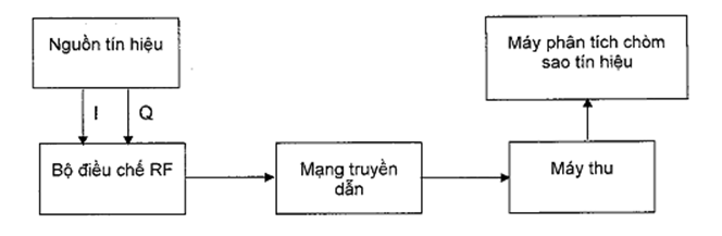
- Provide a standard signal source including I and Q signals for the RF modulator input to obtain the desired QAM formatted modulated signal at the modulator output.
- Set the carrier frequency of the RF modulator according to the channel frequency that the measurement will perform.
2.4.3. Determination method
Adjust the receiver toareceive the modulated signal. Use specialized measuring equipment to determine the MER index.
Figure 3 - Diagram of MER measurement connection
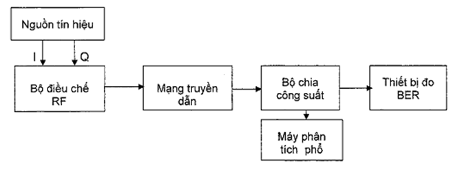
Bit error ratio (BER)development Basic parameter determining the quality of the digital transmission link; the BER parameter is the ratio of the number of erroneous bits to the total number of bits transmitted.
BER < 1development Use specialized measuring equipment to determine the ratio of erroneous bits to the total number of bits transmitted. The receiving equipment must be adjusted to
Measurement diagram as shown in Figure 3.
eliminate linear distortion of the cable television network.
2.5. Figure 4 - Diagram of BER measurement connection lCarrier-to-noise ratio (C/N) with BER = 10
2.5.1. - Methods using measuring devices: The minimum number of sampled calls required for each of the above indicators is 1,500 calls. Determination can be made using one or both of the following methods, or a combination thereof:
Is the ratio between the carrier power level and the noise power level.
2.5.2. Index
C/N > 20 dB with 16 QAM modulation;0-4.
2.5.3. Determination method
C/N > 26 dB with 64 QAM modulation;development C/N > 32 dB with 256 QAM modulation.
Measurement diagram as shown in Figure 4.
Adjust the spectrum analyzer to the channel to be measured, select the center frequency and set the level to display the entire bandwidth. Set the spectrum analyzer resolution to 100 kHz and set the video bandwidth to 100 Hz.
2.6. Measure the peak level of the signal to be measured, unit dB or-4
2.6.1. - Methods using measuring devices: The minimum number of sampled calls required for each of the above indicators is 1,500 calls. Determination can be made using one or both of the following methods, or a combination thereof:
Disconnect the signal to be measured, adjust the input port with the appropriate resistance. Measure the noise power level N, unit dB (and 20 billion VND at the rate of 4.9%/year, and thus, Commercial Bank A V).
2.6.2. Index
- The measuring instrument will display the ratio of carrier power to noise power:
- Figure 5 - Diagram of C/N measurement connection
- Phase jitter is the variation in phase or frequency of the signal in the digital cable television network.
2.6.3. Determination method
The phase jitter of the signal must be within the range from -5° to +5°.无效Use a standard signal generator I/Q and use specialized measuring equipment to determine the phase jitter errordevelopmentObtain the desired QAM modulated signal at the modulator output.
Set the carrier frequency of the modulator for the measurement to be performed.t sV.
Disconnect the signal to be measured, adjust the input port with the appropriate resistor. Measure the noise power level N, unit of measurement is dB (V).t sThe measuring instrument will display the ratio of carrier signal power to noise power:
Figure 5 - Connection diagram for measuring C/N ratiodevelopmentPhase jitter is the variation in phase or frequency of the signal in the digital cable television network.
Measurement diagram as Figure 5.

Phase jitter of the signal must be within the range of -5° to +5°.
2.7. QCVN 85
2.7.1. - Methods using measuring devices: The minimum number of sampled calls required for each of the above indicators is 1,500 calls. Determination can be made using one or both of the following methods, or a combination thereof:
Use a standard I/Q signal generator and a constellation signal analysis device to determine the standard phase jitter error., amended and supplemented by Decree No. 109/2025/NĐ-CP and Decree No. 193/2025/NĐ-CPProvide I and Q signals at the input of the modulator to achieve the desired QAM-modulated signal format.
2.7.2. Index
Set the carrier frequency of the modulator for the measurement to be performed.
2.7.3. Determination method
ng Systems.of ETSI TS 102 - 201 V1.1.1, Digital Video Broadcasting (DVB): Interfaces for DVB Integrated Receiver Decoder (DVB-RD).
aces fordevelopment DVB Integrated Receiver Decoder Specification for use in cable, satellite and terrestrial networks.
EuroBox 2004 Final Version 1.0, Technical Baseline Specification of a Digital Receiver Decoder (IRD) for use in Cable Networks.
Adjust the carrier level of the RF modulator output so that it approximates the carrier level at the subscriber connection point of the digital cable television network under normal operating conditions.
Adjust the frequency channel of the receiving device for the measurement to be performed.
N |||No.The signal constellation analyzer moves to the position where the measurement is required. If the signal constellation analyzer has its own receiver, there is no need to connect an external receiver.
Measurement diagram as Figure 6.
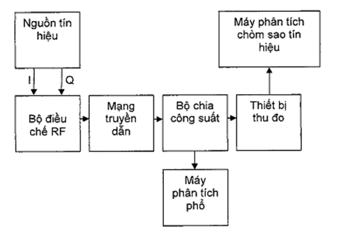
Diagram 6 - Connection diagram for phase jitter measurement
3. MANAGEMENT PROVISIONS
The quality of the digital cable television signal DVB-C at the subscriber connection point must comply with the provisions of this standard.
4. RESPONSIBILITIES OF ORGANIZATIONS AND INDIVIDUALS
4.1. Enterprises providing digital cable television service DVB-C must ensure the provision of cable television signal quality at the subscriber connection point in compliance with the provisions of this standard.
4.2. Enterprises providing digital cable television service DVB-C have the responsibility to implement commitments and declare conformity regarding the quality of the cable television signal at the subscriber connection point according to this standardNo. in INDUSTRIAL EXPLOSIVES - TNP1 EXPLOSIVESdevelopmentand be subject to inspection by the competent state management agency as prescribed.
Chapter 5. ORGANIZATION OF IMPLEMENTATION
5.1. The Telecommunications Authority, the Radio, Television and Electronic Information Administration, and the Provincial Departments of Information and Communications have the responsibility to guide and implement management of organizations and enterprises in accordance with this standard.onIn case the provisions stated in this standard are changed,
5.2. or replaced, MANAGEMENT AND USE OF DEPOSITS AT THE ENVIRONMENT PROTECTION FUND they shall be implemented according to the new document.ì 8688:2011, Digital Cable Television Service According to the DVB-C Standard - Signal at the Subscriber Connection Point - Technical Requirements.
LIST OF REFERENCES
[1] TCVN IEC 60728-1, Cable Networks for Television Signals, Sound Signals and
[2] Interactive Services - Part 1: System Performance.lETSI TR 101 290 V1.2.1 (2001-05), Digital Video Broadcasting (DVB); Measurement Guidelines for DVB Systems. iITU-T J.193 (06-2004), Requirements for the Next Generation of Set-Top Boxes.fOrganizations or individuals in Vietnam or abroad using digital cable television service.
[3] IEC 61883-1 (03-2001), Consumer Audio/Video Equipment - Digital Interface - Part 1: General.
[4] ETSI EN 300 - 429 V1.2.1, Digital Video Broadcasting (DVB): Framing Structure, Channel Coding and Modulation for Cable Systems.iETSI EN 300 - 743 V1.2.1, Digital Video Broadcasting (DVB): Subtitling Systems.
[5] ETSI TS 102 - 201 V1.1.1, Digital Video Broadcasting (DVB): Interfaces for DVB Integrated Receiver Decoder (IRD).
[6] Nordig II, Digital Integrated Receiver Decoder Specification for Use in Cable, Satellite and Terrestrial Networks.l EuroBox 2004 Final Version 1.0, Technical Baseline Specification of a Digital Receiver Decoder (IRD) for Use in Cable Networks.
[7] TCVN 8666:2011, Set-Top Box Equipment in Digital Cable Television Network - Technical Requirements.Number of employees and workers directly involved in the joint venture and association activities of the organization over the last 03 yearsTCVN 8666:2011, Set-Top Box Equipment in Digital Cable Television Network - Technical Requirements
[8] ETSI TS 102 - 201 V1.1.1, Digital Video Broadcasting (DVB): Interfaces for DVB Integrated Receiver Decoder (DVB-RD).rfaces for DVB Integrated Receiver Decoder (DVB-IRD).
[9] Nordig II, Digital Integrated Receiver Decoder Specification for use in cable, satellite and terrestrial networks.organize credit institutions, foreign bank branches are responsible for organizing the implementation of this Circular.ed Receiver Decoder Specification for use in cable, satellite and terrestrial networks.
[10] EuroBox 2004 Final Version 1.0, Technical Baseline Specification of a Digital Receiver Decoder (IRD) for use in Cable Networks.le Networks.
[11] TCVN 8666:2011, Set-Top Box Equipment in Digital Cable Television Network - Technical Requirements.êu cầu kỹ thuật.
原始文件(PDF)
关系图
点击文件即可打开。红色边框=改变效力的关系。