
This Circular stipulates technical requirements for high-speed wireless access devices at the 60 GHz band, including power spectral density, RF output power, transmitter and receiver spurious emissions, medium access control protocols, and integrated antennas. Measurements are conducted within the published operational environment range.
Scope of application
Organizations and individuals engaged in importing, manufacturing, trading, and using high-speed wireless access devices at the 60 GHz band on the territory of Vietnam.
Key points
- The devices must meet technical requirements regarding power spectral density, RF output power, transmitter and receiver spurious emissions, medium access control protocols, and integrated antennas within the published operational environment.
- The maximum RF output power shall not exceed 40 dBm, and the maximum power spectral density is 13 dBm/MHz.
- Spurious emissions from transmitters and receivers must comply with prescribed limits.
- The devices must support medium access control protocols to prevent interference with other radio systems.
- Measurements are conducted within the published operational environment range, including both outdoor and anechoic chamber settings.
🌐 Social impact of this document
- Positive impact: Ensuring safety for other radio systems by limiting spurious emissions.
- Negative impact: Increased production costs due to stricter technical requirements.
❓ Frequently asked questions
What is the maximum RF output power of the device specified?
The maximum RF output power shall not exceed 40 dBm.
What is the maximum allowable power spectral density?
The maximum power spectral density corresponds to when the device operates at its highest transmission power level, not exceeding 13 dBm/MHz.
How must the devices comply with medium access control protocol requirements?
The devices must support medium access control protocols and have the capability to activate in all situations.
Where are measurements conducted?
Measurements are conducted at outdoor locations or in anechoic chambers, depending on frequency band requirements.
If only one antenna element is tested, how should the measurement results be adjusted?
Measurement results of the active element must be calibrated appropriately to reflect the entire system (all transmission elements).
Full text
CIRCULAR
Issuing the "National Technical Regulation on Radio Emission for High-Speed Wireless Access Devices in the 60 GHz Band"
Pursuant to the Law on Radio Frequency dated November 23, 2009; The Minister of Information and Communications issues this Circular to stipulate the National Technical Regulation on Radio Emission for High-Speed Wireless Access Devices in the 60 GHz Band.
_______________
Pursuant to the Law on Standards and Technical Regulations dated June 29, 2006;
Pursuant to the Law on Telecommunications dated November 23, 2009;
Along with this Circular, the National Technical Regulation on Radio Emission for High-Speed Wireless Access Devices in the 60 GHz Band (QCVN 88:2015/BTTTT) is issued.
WHEREAS, Decree No. 127/2007/NĐ-CP dated August 1, 2007 of the Government detailing and guiding the implementation of certain provisions of the Law on Technical Standards and Regulations;
Based on Decree No. 132/2013/ND-CP dated October 16, 2013 of the Government on the functions, tasks, powers, and organizational structure of the Ministry of Information and Communications;
Pursuant to the proposal of the Director of the Science and Technology Department,
This Circular takes effect from January 1, 2016.
Article 1. The Heads of the Office, Department Heads of Science and Technology, Heads of Departments under the Ministry of Information and Communications, Directors of Provincial Information and Communications Departments under the Central Government, and relevant organizations and individuals are responsible for implementing this Circular.
Article 2. NATIONAL TECHNICAL REGULATION ON RADIO EMISSION FOR HIGH-SPEED WIRELESS ACCESS DEVICES IN THE 60 GHZ BAND
Article 3. National technical regulation on radio emission of wireless access equipments operating at Multiple-Gigabit data rates in the 60 GHz band
QCVN 88:2015/BTTTT
1.5. Symbols and Abbreviations
1.5.1. Symbols
2.4.4. Support for Multi PLP
Chapter 1. GENERAL PROVISIONS
1.1. Scope of Application
1.2. Applicability
1.3. Referenced Documents
1.4. Terms and Definitions
1.5.2. Abbreviations
2.1. Environmental Conditions
2.2. Specified Requirements
Chapter 2. TECHNICAL PROVISIONS
2.2.1. Power Spectral Density
2.2.1.2. Limits
2.2.1.3. Measurement Method
Unwanted emission from the receiver is radiation at any frequency by the equipment and antenna. The value of unwanted emission must be measured by the effective radiated power level including: Enclosure radiation and integrated equipment or with dedicated antennas.
2.2.2. RF Output Power
2.2.2.2. Limits
2.2.2.3 Measurement Method
2.2.2.1. Definition
2.2.3. Transmitter Spurious Emission
2.2.3.3. Measurement Method
2.2.4. Receiver Spurious Emission
2.2.3.1. Definition
2.2.3.2. Limits
2.2.4.2. Limits
2.2.4.3. Measurement Method
2.2.4.1. Definition
2.2.5. Access Protocol
2.2.5.2. Requirements
2.2.6. Integrated Antenna
2.2.5.1. Definitions
2.2.6.2. Requirements
3.1. Measurement Environmental Conditions
Customer assistance service is a service that provides answers to inquiries, advice, guidance on using the service, accepts requests, and provides information to customers about IPTV services on the fixed terrestrial telecommunications network.
3.2. Interpretation of Measurement Results
3. MEASUREMENT METHODS
3.3. Measurement Methods
3.3.1. Product Information
3.3.2. Modulation, Frequency and Configuration for Measurement
3.3.3. Measurement of Power Spectral Density
3.3.4. Measurement of RF Output Power
3.3.5. Measurement of Transmitter Spurious Emission
3.3.5.1. Preliminary Scan (Pre-scan)
3.3.5.2. Specific Emission Measurement
3.3.6. Measurement of Receiver Spurious Emission
3.3.6.1. Preliminary Scan
3.3.6.2. Specific Emission Determination Measurement
Appendix A (Provisions) Table of Requirements for Measured Indicators
Appendix B (Provisions) Measurement Position and Radiation Layout
5. RESPONSIBILITIES OF ORGANIZATIONS AND INDIVIDUALS
5. RESPONSIBILITIES OF ORGANIZATIONS AND INDIVIDUALS
6. IMPLEMENTATION ORGANIZATION
Appendix C (Provisions)
General Description of Measurement
QCVN 88:2015/BTTTT is based on EN 302 567 v1.2.1 (2012-1): Broadband Radio Access Networks (BRAN); 60 GHz Multiple-Gigabit WAS/RLAN Systems; Harmonized EN covering the essential requirements of Article 3.2 of the R&TTE Directive of the European Telecommunications Standards Institute (ETSI).Drafted by the Radio Frequency Management Department, reviewed and submitted for approval by the Department of Science and Technology, and issued together with Circular No. 14/2015/TT-BTTTT dated June 15, 2015 by the Ministry of Information and Communications.
QCVN 110:2017/BTTTT was compiled by the Post and Telecommunications Science and Technology Institute, reviewed by the Department of Science and Technology, and promulgated along with Circular No. 24/2017/TT-BTTTT dated October 17, 2017.
Foreword
This standard specifies technical requirements for high-speed wireless access devices up to multiple gigabits for use in indoor wireless local area networks (WLAN) or short-range personal wireless networks (WPAN) operating in the 60 GHz band. It does not apply to wireless devices used for outdoor fixed local area network extension or point-to-point fixed wireless transmission applications operating in the 60 GHz band.
QCVN 88:2015/BTTTT This standard applies to organizations and individuals engaged in importing, manufacturing, trading, and using devices within the scope of this standard on the territory of Vietnam.
1.5. Symbols and Abbreviations
1.5.1. Symbols
Chapter 1. GENERAL PROVISIONS
1.1. Scope of Application
ERC Recommendation 74-01 (2011): "Unwanted Emissions in the Spurious Domain".
ETSI TR 100 028 (V1.4.1) - (all parts): "Electromagnetic Compatibility and Radio Spectrum Matters (ERM); Uncertainties in the Measurement of Mobile Radio Equipment Characteristics".
1.2. Applicability
ITU-R Recommendation SM.1539-1 (2002): "Variation of the Boundary Between the Out-of-Band and Spurious Domains Required for the Application of Recommendations ITU-R SM.1541 and ITU-R SM.329".
1.3. Referenced Documents
1.4.1. 60 GHz Band
(60 GHz band)
The frequency range of operation of the device, from 57 GHz to 66 GHz.
1.4. Terms and Definitions
1.4.2. Activity Factor (activity factor)
The percentage of time the device is active during a one-minute period.
1.4.3. Channel Separation (channel separation)
The minimum distance (in MHz) between the center frequencies of any two adjacent channels in the channel plan of the device.
1.4.4. Environmental Profile (environmental profile)
The set of environmental conditions that must be ensured during the testing of the device.
1.4.5. Integrated Antenna An antenna designed to be attached to the device without using standard connectors and considered part of the device.
1.4.6. Mean Power
(mean power) (integral antenna)
The average power delivered to the transmission medium provided by the transmitter to the antenna over a sufficiently long period compared to the lowest modulation frequency under normal operating conditions.
1.4.7. Occupied Bandwidth (occupied bandwidth)
The bandwidth of the signal corresponding to the -6 dBc signal power level.1.4.8. Smart Antenna Systems (smart antenna systems)
A device that uses a combination of multiple antenna elements for receiving and transmitting signals with signal processing capabilities to enhance transmission and reception performance. Relative Decibel (compared to the maximum power density of the transmitted signal)
dBm
Decibel corresponding to 1 mW dBr
Relative Decibel (compared to a specified maximum power level)
1.5.2. Abbreviations
2.1. Environmental Conditions
dBm ChS
Channel Separation Equivalent Isotropically Radiated Power
FLANE Fixed Local Area Network Extension
2.2. Specified Requirements
|
OBw |
Occupied Bandwidth |
Occupied Bandwidth |
|
EIRP |
Equivalent Isotropically Radiated Power |
PDL |
|
Power Spectral Density Limit |
RBw |
Resolution Bandwidth |
|
RLAN |
Radio Local Area Network |
Radio Local Area Network |
|
R&TTE |
Radio and Telecommunications Terminal Equipment |
Radio and Telecommunications Terminal Equipment |
|
UUT |
Root Mean Square |
Unit Under Test |
|
RF |
Radio Frequency |
Radio Frequency |
|
Unit Under Test |
VBw |
Video Bandwidth |
|
Video Bandwidth |
WAS |
Wireless Access System |
|
Wireless Access System |
WLAN |
Wireless Local Area Network |
|
Wireless Local Area Network |
WPAN |
Wireless Personal Area Network |
|
Wireless Personal Area Network |
The technical requirements stipulated in this technical regulation apply to the operational environmental conditions of the device. These conditions must be published by the device manufacturer. The device must meet the technical requirements stipulated in this technical regulation when operating under the published operational environmental conditions. |
Hệ thống Truy Cập Vô Tuyến |
|
WLAN |
Mạng Nội Bộ Vô Tuyến |
Wireless Local Area Network |
|
WPAN |
Mạng Cá Nhân Vô Tuyến |
Wireless Personal Area Network |
Chapter 2. TECHNICAL PROVISIONS
2.2.1. Power Spectral Density
Các yêu cầu kỹ thuật quy định tại quy chuẩn kỹ thuật này áp dụng cho điều kiện môi trường hoạt động của thiết bị. Các điều kiện này phải được nhà sản xuất thiết bị công bố. Thiết bị phải đảm bảo đáp ứng các yêu cầu kỹ thuật quy định tại quy chuẩn kỹ thuật này khi làm việc trong điều kiện môi trường hoạt động được công bố.
2.2. Technical Requirements
2.2.1.3. Measurement Method
Unwanted emission from the receiver is radiation at any frequency by the equipment and antenna. The value of unwanted emission must be measured by the effective radiated power level including: Enclosure radiation and integrated equipment or with dedicated antennas.
The power spectral density is the average equivalent isotropic radiated power (EIRP) per 1 MHz during the transmission of a data packet.
2.2.2. RF Output Power
The maximum power spectral density corresponds to the case where the device operates at the highest published transmission power level. For smart antenna systems, the upper limit corresponds to the configuration that achieves the highest EIRP.
The limits on power spectral density are specified in Table 1.
Table 1 - Power Spectral Density Limits (PDL)
|
Scope of application |
Power Spectral Density Limit (EIRP) |
|
Indoor and Outdoor |
13 dBm/MHz |
2.2.2.2. Limits
The measurement method is specified in Section 3.3.3.
2.2.2.3 Measurement Method
2.2.2.1. Definition
The maximum radio frequency (RF) output power is the average equivalent isotropic radiated power (EIRP) of the device during the transmission of a data packet.
2.2.3. Transmitter Spurious Emission
The maximum RF output power corresponds to the case where the system operates at the highest published power level. For smart antenna systems, the upper limit corresponds to the configuration that achieves the highest EIRP.
The limits on RF output power are specified in Table 2.
Table 2 - Maximum RF Output Power (EIRP)
|
Scope of application |
Maximum RF Output Power (EIRP) |
|
Indoor and Outdoor |
40 dBm |
2.2.3.3. Measurement Method
The measurement method is specified in Section 3.3.4.
2.2.4. Receiver Spurious Emission
2.2.3.1. Definition
Unwanted emissions from the transmitter are unwanted emissions in the out-of-band region when the device is transmitting signals. The boundaries of the out-of-band region start at a deviation of +/-250% bandwidth from the nominal center frequency for bandwidths up to and including 500 MHz, and from a deviation of +/-(500 MHz + 1.5 times the bandwidth) for bandwidths greater than 500 MHz.
2.2.3.2. Limits
Unwanted emissions from the transmitter must comply with the limits specified in Table 3.
NOTE: These limits apply to the measured transmission power levels at the antenna port.
Table 3 - Limits on Unwanted Transmitter Emissions
|
Frequency Range |
Out-of-Band Emission Limit |
Measured Bandwidth |
|
30 MHz to 47 MHz |
47 MHz to 74 MHz |
-54 dBm |
|
47 MHz to 74 MHz |
-54 dBm |
-54 dBm |
|
74 MHz to 87.5 MHz |
47 MHz to 74 MHz |
-54 dBm |
|
87.5 MHz to 118 MHz |
-54 dBm |
-54 dBm |
|
118 MHz to 174 MHz |
47 MHz to 74 MHz |
-54 dBm |
|
174 MHz to 230 MHz |
-54 dBm |
-54 dBm |
|
230 MHz to 470 MHz |
47 MHz to 74 MHz |
-54 dBm |
|
470 MHz to 862 MHz |
-54 dBm |
-54 dBm |
|
862 MHz to 1 GHz |
47 MHz to 74 MHz |
-54 dBm |
|
1 GHz to 132 GHz |
5.470 GHz to 26 GHz |
2.2. Measurement Methods |
2.2.4.2. Limits
The measurement method is specified in Section 3.3.5.
2.2.4.3. Measurement Method
2.2.4.1. Definition
Unwanted emissions from the receiver are unwanted emissions in the out-of-band region when the device is receiving signals.
2.2.5. Access Protocol
Unwanted emissions from the receiver must comply with the limits specified in Table 4.
NOTE: These limit values apply to the measured transmission power levels at the antenna port.
Table 4 - Limits on Unwanted Receiver Emissions
|
Frequency Range |
Out-of-Band Emission Limit |
Measured Bandwidth |
|
30 MHz to 1 GHz |
-57 dBm |
-54 dBm |
|
1 GHz to 132 GHz |
-47 dBm |
2.2. Measurement Methods |
2.2.5.2. Requirements
The measurement method is specified in Section 3.3.6.
2.2.6. Integrated Antenna
2.2.5.1. Definitions
The channel access protocol is the mechanism applied to allow shared use of the frequency band with other devices in a wireless network.
2.2.6.2. Requirements
High-speed 60 GHz band wireless access devices must support a channel access protocol and must be capable of activation in all situations.
3.1. Measurement Environmental Conditions
Customer assistance service is a service that provides answers to inquiries, advice, guidance on using the service, accepts requests, and provides information to customers about IPTV services on the fixed terrestrial telecommunications network.
Integrated antennas are designed to be fixedly attached to the device without using standard connectors and are considered part of the device.
3.2. Interpretation of Measurement Results
Integrated antennas must be used to minimize harmful interference to other radio systems.
3. MEASUREMENT METHODS
3.3. Measurement Methods
The measurements required under this standard must be performed within the published operational environment boundary limits.
If measurement results vary depending on environmental conditions, measurements must be conducted under different environmental conditions within the published operational environment boundary limits.
3.3.1. Product Information
The recording of measurement results in the test report according to this standard is defined as follows:
· Compare the measured value with the corresponding limit to determine whether the device meets the requirements of this standard.
· The uncertainty of each measured parameter must be recorded in the test report.
· The measurement uncertainty recorded for each measurement must be equal to or less than the values specified in Table 5.
For the measurement methods prescribed in this standard, the measurement uncertainty must be calculated with an expansion factor (coverage factor) k = 1.96 or k = 2 (allowing confidence levels of 95% and 95.45%, respectively, assuming a normal distribution of actual measurement errors). The calculation principle of measurement error follows ETSI TR 100 028 v1.4.1.
Table 5 - Maximum Measurement Uncertainty
|
Parameter |
Measurement Uncertainty |
|
RF Frequency |
±1 × 10⁻⁵ |
|
RF Output Power |
±8 dB |
|
Spurious emissions |
±8 dB |
|
Moisture content |
±5 % |
|
Salinity |
±1 °C |
|
Time |
±10 % |
3.3.2. Modulation, Frequency and Configuration for Measurement
3.3.3. Measurement of Power Spectral Density
The following parameters must be published by the equipment manufacturer to perform measurements and to declare compliance with the standard:
a) Operating frequency channels: these are the central frequencies that the UUT can adjust. If the device supports multiple sub-channels (for example, allowing operation with different channel widths), these frequency channels must be published.
b) Modulation types used by the UUT.
c) Channel access methods used by the UUT.
d) Description of integrated antennas used by the device and measures to prevent users from connecting to another antenna.
3.3.4. Measurement of RF Output Power
The modulation method used for testing should use the typical modulation method of the device. In cases where the device does not have the capability for continuous RF transmission, the testing modulation method should be as follows:
a) The RF transmission emitted is identical for each transmission.
b) Transmission occurs regularly over time.
c) Transmission sequences can be repeated accurately.
If the device uses multiple modulation methods with different RF characteristics, the worst-case modulation method must be used and this method must be published along with the reasons for the worse performance compared to other modulation methods.
All measurements must be performed on the following frequency channels within the published frequency band range of the device:
a) The channel with the lowest operating frequency.
b) The channel with the highest operating frequency.
c) The channel closest to the midpoint of the operating frequency band.
If the UUT has the capability to support multiple bandwidths for wideband transmission, measurements must be performed separately for each bandwidth.
RF output power must also be tested in narrowband mode if necessary.
The channel spacing (ChS) must be calculated based on the smallest frequency difference in MHz between any two central frequencies in the device's channel plan.
If the RF output power level is adjustable, all measurements must be performed at the highest power level.
In the case of using smart antenna systems, the UUT should be configured to operate at the maximum RF output power level, and the methods of implementation must be recorded in the measurement report.
Emission measurements must be carried out in cases where integrated antennas are used and in cases where there is no suitable direct measurement method for that device.
3.3.5. Measurement of Transmitter Spurious Emission
The highest power spectral density, under the measurement conditions specified in Sections 3.1, 3.2, and 3.3.2, must be measured using a measurement setup described in Appendix B, and the measurement procedures available in Appendix C must be used and recorded for equipment conformity assessment as stipulated in Section 2.2.1.
The highest power spectral density is determined using a spectrum analyzer with an appropriate bandwidth corresponding to the type of modulation used and combined with an RF power meter.
For the purpose of this measurement, the minimum operating time of the transmitter must be 10 µs. For devices where the transmitter's operating time is less than 10 µs, the measurement method must be recorded in the measurement report.
The measurement procedure is as follows:
Step 1:
Set up the parameters for the spectrum analyzer:
a) Center frequency: the center frequency of the channel to be measured.
b) Resolution bandwidth (RBw): 1 MHz.
c) Video bandwidth (VBw): 1 MHz.
d) Frequency span: twice the nominal channel width.
đ) Detector mode: Peak.
e) Trace mode: Maximum Hold (max hold).
Step 2:
When the sweep is complete, determine the peak value of the power envelope and record the corresponding frequency value.
Step 3:
Change the settings of the spectrum analyzer as follows:
a) Center frequency: equal to the frequency recorded in step 2.
b) Resolution bandwidth (RBw): 1 MHz.
c) Video bandwidth (VBw): 1 MHz.
d) Frequency span: 3 MHz.
đ) Sweep time: 1 minute.
e) Detector mode: RMS Average, Sample, or Average (excluding video average).
g) Trace mode: Maximum Hold (max hold).
For devices with an occupied bandwidth greater than 100 MHz, a resolution bandwidth other than 1 MHz, within the range from 1 MHz to 100 MHz, may be used. In this case, the power density limit in step 4 is determined as follows: PDL (RBw) = PDL (1 MHz) + 10 x Log (RBw), where RBw is the resolution bandwidth used in MHz, PDL (1 MHz) is the power density limit with a resolution bandwidth of 1 MHz, and PDL (RBw) is the power density limit with the resolution bandwidth RBw set above. The video bandwidth is set to the resolution bandwidth, and the frequency span is set to three times the resolution bandwidth.10When the sweep is completed, use the "View" option on the spectrum analyzer to observe the signal.
Step 4:
Determine the highest peak value and place the cursor on this value. This value is recorded as the highest average power level (power spectral density) D in 1 MHz (or in another resolution bandwidth as presented above).
Additionally, if the spectrum analyzer has the capability to measure power spectral density, this function can be used to display the power spectral density D dBm/1 MHz (or in another resolution bandwidth as presented above).
The highest EIRP power spectral density is calculated from the measured power density (D) above and the duty cycle t according to the following formula and must be recorded in the measurement report. Note that the power spectral density PD is specifically defined for a resolution bandwidth of 1 MHz (or alternatively by another resolution bandwidth as presented above).
h) PD = D + 10 × log (1 / t).
If the bandwidth of the spectrum analyzer does not follow a Gaussian distribution, a suitable correction factor must be used.10 The RF output power, under the measurement conditions specified in Sections 3.1, 3.2, and 3.3.2, is measured using a measurement setup as described in Appendix B, and the measurement procedures available in Appendix C must be used and recorded for equipment calibration as stipulated in Section 2.2.2.
The center frequency of the device must be established within the 60 GHz band.
3.3.5.1. Preliminary Scan (Pre-scan)
Step 1:
Using appropriate attenuators, the measuring instrument must be coupled to the diode splitter or equivalent device. The output of the diode splitter is connected to the Y channel of the oscillator generator or equivalent power meter.
The combination of the diode splitter and the oscillator generator must be capable of displaying the transmitter output signal cycle.
a) The observed duty cycle (Tx_on / (Tx_on + Tx_off)) is denoted as t (0 < t ≤ 1) and must be recorded in the measurement report. For the purpose of testing, the device must operate with a duty cycle of at least 0.1.
b) d) The RF output power of the transmitter when operating at the maximum power level must be measured using a spectrum analyzer with an integration factor greater than or equal to five times the transmitter's repetition period. The observed value is recorded as "A" (dBm).
c) đ) The EIRP power value is calculated from the aforementioned power A and the observed duty cycle t according to the following formula and recorded in the measurement report.
Step 2:
e) P = A + 10 x Log (1/t)
The spurious emissions of the transmitter, under the measurement conditions specified in Sections 3.1, 3.2, and 3.3.2, are measured using the measurement setup prescribed in Appendix B and the measurement procedures prescribed in Appendix C, and are recorded according to the requirements stipulated in Section 2.2.3, taking into account the actual gain of the UUT antenna.
In the case of emission measurements performed on array antenna systems using symmetric power distribution across the available transmit chains, the UUT should be configured (if possible) to activate only one transmitting element while deactivating the other transmitting elements. If this requirement cannot be met, the method used must be recorded in the measurement report.H If only one transmitting element is tested, the measurement results of the active element must be adjusted appropriately to reflect the entire system (all transmitting elements).10NOTE: The transmission power of the system equals the transmission power (mW) of one transmitting element multiplied by the number of transmitting elements.
3.3.5.2. Specific Emission Measurement
For the purpose of this measurement, the UUT must be configured to operate at the highest duty cycle and maximum output power level.
Trong trường hợp các phép đo phát xạ thực hiện trên hệ thống ăng-ten mảng mà sử dụng phân bố công suất đối xứng qua các chuỗi phát khả dụng thì UUT nên được cấu hình (nếu có thể) để chỉ một phần tử truyền (ăng-ten) được kích hoạt trong khi các phần tử truyền khác bị vô hiệu hóa. Trường hợp không thể thực hiện được yêu cầu trên thì phải ghi vào báo cáo đo kiểm phương pháp đã sử dụng.
Nếu chỉ có một phần tử truyền được kiểm tra thì kết quả đo của phần tử tích cực phải được hiệu chỉnh phù hợp với toàn bộ hệ thống (tất cả phần tử truyền).
CHÚ THÍCH: Công suất phát xạ của hệ thống bằng công suất phát xạ (mW) của một phần tử truyền nhân với số lượng các phần tử truyền.
Với mục đích của phép đo này, UUT phải được cấu hình để hoạt động ở chu kỳ lớn nhất và mức công suất đầu ra lớn nhất.
3.3.6. Measurement of Receiver Spurious Emission
The procedures below are used to determine the level of spurious emissions of the UUT.
Step 1:
The sensitivity of the spectrum analyzer should be set to ensure that the noise floor is at least 6 dB below the limit specified in Table 3.
Step 2:
Emissions must be measured over the frequency range from 30 MHz to 1 GHz.
a) Resolution bandwidth (RBw): 100 kHz.
b) Video bandwidth (VBw): 100 kHz.
c) Detector mode: Average.
d) Trace mode: Maximum hold (max hold).
đ) Sweep time: For non-continuous transmission, the sweep time must be long enough such that for each 100 kHz frequency step, the measurement time is greater than twice the UUT's transmission time.
Emissions must be measured over the frequency range from 1 GHz to 132 GHz:
e) Resolution bandwidth (RBw): 1 MHz.
g) Video bandwidth (VBw): 1 MHz.
h)||| Detector mode: Average.
i) Trace mode: Maximum hold.
k) Sweep time: For non-continuous transmission, the sweep time must be long enough such that for each 1 MHz frequency step, the measurement time is greater than twice the UUT's transmission time.
If the equipment does not have the capability to measure up to the 132 GHz band, the highest frequency recorded in the test report shall be noted.
Any emission determined during the scanning process that lies below the limit specified within a 6 dB range must be measured separately using the methods prescribed in Section 3.3.5.2 and then compared with the limits in Table 3. If the measurement is performed at a different distance than specified, the equivalent field strength value must be calculated.
3.3.6.1. Preliminary Scan
Unwanted emissions in the low or high spurious emission bands identified from the preliminary scan measurement above must be accurately measured using the following methods.
The low spurious emission band is defined as the band with a frequency range from the lowest measurable frequency to the nominal center frequency minus 250% of the channel width (ChS) with ChS ≤ 500 MHz or to the nominal center frequency minus (500 MHz + 1.5 × ChS) with the channel width ChS > 500 MHz.
The high spurious emission band is defined as the band with a frequency range from the nominal center frequency plus 250% of the channel width (ChS) with ChS ≤ 500 MHz or from the nominal center frequency plus (500 MHz + 1.5 × ChS) with the channel width ChS > 500 MHz, to the highest measurable frequency.
Use the steps below to measure specific spurious emissions that were preliminarily identified through the measurement at Section 3.3.5.1.
For continuous transmission signals, measure using the spectrum analyzer's average display detector. In other cases, the measurement is conducted only during the transmitter's operating time.
Step 1:
The emission level must be measured in the time domain with the following settings on the spectrum analyzer:
a) Center frequency: The emission frequency determined during the preliminary scan.
b) Resolution bandwidth (RBw): 100 kHz for frequencies below 1 GHz and 1 MHz for frequencies above 1 GHz.
c) Video bandwidth (VBw): 100 kHz for frequencies below 1 GHz and 1 MHz for frequencies above 1 GHz.
d) Frequency span: 0 Hz.
đ) Sweep time: Suitable to capture a data packet transmission.
e) Trigger: Video trigger.
g) Detector mode: Average.
h)||| Trace mode: Continuous direct display (clear write).
The center frequency (fine tuning) must be adjusted to capture the peak level of the data packet transmission.
Step 2:
Change the following settings on the spectrum analyzer:
i) Detector mode: Average display (video average), minimum 100 sweeps.
The measured values are the average power of the emission during the data packet transmission time. The measured values are recorded and compared with the limits in Table 3.
3.3.6.2. Specific Emission Determination Measurement
Spurious emissions of the receiver, under the measurement conditions specified in Sections 3.1, 3.2, and 3.3.2, are measured using the measurement setup specified in Appendix B and the measurement procedure specified in Appendix C, and are recorded according to the requirements specified in Section 2.2.4, taking into account the actual antenna gain of the UUT.
In the case where the emission measurement is performed on an antenna array system using uniform receiving antenna elements, if possible, the UUT should be configured so that only one receiving antenna element is activated while the others are disabled. If this cannot be done, the method used must be recorded in the test report.
If only one antenna element is tested, the measurement results of that element must be calibrated to match the entire system (all antenna elements).
NOTE: The emission power of the system equals the emission power (mW) corresponding to one antenna element multiplied by the total number of elements.
The UUT must be configured in continuous reception mode or must operate in a mode where no transmission occurs.
Appendix A (Provisions) Table of Requirements for Measured Indicators
The procedures below are used to determine the level of spurious emissions of the UUT.
Step 1:
The sensitivity of the spectrum analyzer must be set to ensure that the noise floor is at least 6 dB below the limit specified in Table 4.
Step 2:
Emissions must be measured over the frequency range from 30 MHz to 1 GHz:
a) Resolution bandwidth (RBw): 100 kHz.
b) Video bandwidth (VBw): 100 kHz.
c) Detector mode: Average.
d) Trace mode: Maximum hold (Max Hold).
Emissions also must be measured over the frequency range from 1 GHz to 132 GHz:
đ) Resolution bandwidth (RBw): 1 MHz.
e) Video bandwidth (VBw): 1 MHz.
g) Detector mode: Average.
h)||| Trace mode: Maximum hold (max hold).
If the equipment does not have the capability to measure up to the 132 GHz band, the highest frequency measured must be recorded in the test report.
Any emission determined during the scanning process above lying below the limit specified within a 6 dB range must be measured separately using the measurement procedure prescribed in Section 3.3.6.2 and then compared with the limits in Table 4.
Appendix B (Provisions) Measurement Position and Radiation Layout
The following steps are used to accurately measure the spurious emissions identified in the preliminary scan measurements above.
The measured values must be recorded and compared with the limits in Table 4. If the measurement is performed at a different distance than specified, the equivalent field strength value must be calculated.
Set the parameters for the spectrum analyzer as follows:
a) Center frequency: The emission frequency determined during the preliminary scan.
b) Resolution bandwidth (RBw): 100 kHz for frequencies below 1 GHz and 1 MHz for frequencies above 1 GHz.
c) Video bandwidth (VBw): 100 kHz for frequencies below 1 GHz and 1 MHz for frequencies above 1 GHz.
d) Detector mode: Average.
d) Trace mode: Maximum hold (max hold).
5. RESPONSIBILITIES OF ORGANIZATIONS AND INDIVIDUALS
High-speed radio access devices in the 60 GHz band subject to regulation as provided in Section 1.1 must comply with the technical regulations stipulated in this standard.
5. RESPONSIBILITIES OF ORGANIZATIONS AND INDIVIDUALS
Organizations, individuals related responsible for implementing conformity certification and announcing conformity certification high-speed radio access devices in the 60 GHz band in accordance with the regulations on conformity certification and announcement for specialized information technology and telecommunications products. and be subject to inspection by state management agencies in accordance with current regulations.
6. IMPLEMENTATION ORGANIZATION
6.1. The Telecommunications Agency and Provincial Departments of Information and Communications shall implement guidance and manage high-speed wireless access devices operating at the 60 GHz band according to this Standard.
6.2. In case there are changes, additions, or replacements to the provisions of this Standard, they shall be carried out in accordance with the new document.
ANNEX A
Product Name, Goods According to QCVN
Table of requirements for measurement indices
Appendix A.1 - Table of measurement requirements
|
Specific requirements |
Application conditions |
Measurement index |
||||
|
Serial number |
Description |
Refer to clause number |
U/C |
Conditions |
E/O |
Refer to clause number |
|
1 |
Radio and Telecommunications Terminal Equipment |
2.2.1 |
The decision to switch the issuance of coats, overcoats, windbreakers, and down jackets to other uniforms for civil servants working at the National Market Management and Development Agency is decided by the Minister of Industry and Trade. |
|
E |
3.3.3 |
|
2 |
RF Output Power |
2.2.2 |
The decision to switch the issuance of coats, overcoats, windbreakers, and down jackets to other uniforms for civil servants working at the National Market Management and Development Agency is decided by the Minister of Industry and Trade. |
|
E |
3.3.4 |
|
3 |
Spurious emissions from transmitter |
2.2.3 |
The decision to switch the issuance of coats, overcoats, windbreakers, and down jackets to other uniforms for civil servants working at the National Market Management and Development Agency is decided by the Minister of Industry and Trade. |
|
E |
3.3.5 |
|
4 |
Spurious emissions from receiver |
2.2.4 |
The decision to switch the issuance of coats, overcoats, windbreakers, and down jackets to other uniforms for civil servants working at the National Market Management and Development Agency is decided by the Minister of Industry and Trade. |
|
E |
3.3.6 |
|
5 |
Access protocol |
2.2.5 |
The decision to switch the issuance of coats, overcoats, windbreakers, and down jackets to other uniforms for civil servants working at the National Market Management and Development Agency is decided by the Minister of Industry and Trade. |
|
X |
|
|
6 |
Integrated antenna |
2.2.6 |
The decision to switch the issuance of coats, overcoats, windbreakers, and down jackets to other uniforms for civil servants working at the National Market Management and Development Agency is decided by the Minister of Industry and Trade. |
|
X |
|
NOTE
U : Apply unconditionally
C : Apply conditionally
E : Apply prescribed measurement method
O: Apply alternative measurement method
X : No specific measurement provided.
Provisions on the HS Code of Terrestrial Mobile Radio Equipment and Terrestrial Radio Relay Equipment
Product Name, Goods According to QCVN
Measurement location and radiation arrangement
B.1. Measurement location
B.1.1. Outdoor measurement location
The term "outdoor" is understood from an electromagnetic field perspective. The measurement location may be outdoors or in a position with transparent ceilings and walls to radio waves at the frequencies under consideration.
Outdoor measurement locations can be used to perform measurements using the radiation measurement methods described in Section 3.3. Both absolute and relative measurements can be performed on transmitters or receivers. Absolute field strength measurements require calibration of the measurement location.
A minimum measurement distance of 3 meters is used for frequencies up to 1 GHz. For frequencies above 1 GHz, measurements can be taken at any suitable measurement distance. The size of the device (excluding antennas) must be less than 20% of the measurement distance. The height of the device or substitute antenna is 1.5 meters; the height of the measuring antenna (of the transmitter or receiver) varies from 1 meter to 4 meters.
It is necessary to ensure that reflections from nearby objects do not affect the measurement results, specifically:
- There should be no unrelated measurement objects larger than a quarter wavelength of the highest measurement frequency in the vicinity of the measurement location;
- Cables should be as short as possible; parts of cables placed on the ground plane or below the ground plane should be minimized; low impedance cables must be shielded.
The general measurement layout is illustrated in Figure B.1.
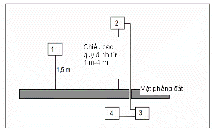
Figure B.1 - Measurement layout
1) Medium Frequency
2) Measuring antenna
3) High-pass filter (as required)
4) Spectrum analyzer or measurement receiver
B.1.2. Anechoic chamber
B.1.2.1. Overview
An anechoic chamber is a fully enclosed room lined with materials that absorb radio frequencies and simulate free space conditions. It is an alternative environment for performing the radiation measurements described in Section 3.3. Both absolute and relative measurements can be performed on transmitters and receivers. Absolute field strength measurements require calibration of the anechoic chamber. Inside the anechoic chamber, the measuring antenna, the device under test, and auxiliary antennas are arranged at a fixed height on the floor, similar to outdoor measurements.
B.1.2.2. Description
An anechoic chamber must meet the isolation attenuation and wall reflection attenuation requirements specified in Figure B.2. Figure B.3 shows an example of an anechoic chamber construction with a floor area of 5 m x 10 m and a height of 5 m. The ceiling and walls are covered with pyramid-shaped absorber material approximately 1 meter high. The floor is surrounded by special absorber materials. The internal space dimensions of the anechoic chamber are 3 m x 8 m x 3 m, allowing for the maximum measurement distance of 5 meters along the central axis of the room. Absorbers placed on the floor eliminate reflections from the floor, thus the antenna height does not need to change. Chambers of different sizes can also be used. Additionally, chambers with a floor area of 2.5 m x 3 m and a height of 5 m can be utilized.
B.1.2.3. Effects of parasitic reflections
For free-space propagation at far-field distances, the relationship between field strength E and distance R is given by the formula E = E°x(R°/R), where E° is the reference field strength and R° is the reference distance. This relationship allows for relative measurements since all constants have been eliminated in the ratio and cable loss as well as antenna or antenna size variations are not significant factors.
Taking the logarithm of the above equation makes it easy to see deviations from the ideal curve due to the ideal correlation between field strength and distance being a straight line. Thus, actual deviations can be easily observed. This indirect method quickly and easily identifies any interference caused by reflections and simplifies the complexity compared to directly measuring reflection loss.
With anechoic chambers of the above dimensions, at frequencies below 100 MHz, the far-field conditions are not met, but due to stronger wall reflections, caution must be exercised during calibration. For medium frequencies from 100 MHz to 1 GHz, the field strength dependence on distance closely matches calculations. Above 1 GHz, due to multiple reflections, the field strength dependence on distance will not correlate tightly.
B.1.2.4. Calibration and usage mode
Calibration and usage mode are similar to outdoor measurement locations, with the only difference being that the measuring antennas do not need to adjust height during the selection of maximum values, which simplifies the measurement process.
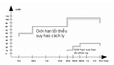
Figure B.2 - Isolation and Reflection Requirements
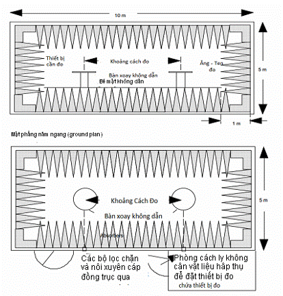
Figure B.3 - Anechoic Chamber for Free-Space Simulation Measurements
B.2. Measuring Antenna
When the measurement position is used to measure radiation, the measurement antenna is used to detect the electromagnetic field of both the sample being measured and the substitute antenna. When the measurement position is used to measure the characteristics of the receiver, the antenna will be used as a transmitting antenna. This antenna will be mounted on a support that allows it to be used in both vertical and horizontal polarization and simultaneously allows the height to be adjusted from the center of the antenna relative to the ground within the specified range. Measurement antennas with high directivity should be used. The size of the measurement antennas along the measurement axis must not exceed 20% of the measurement distance. The antenna shall include necessary up/down converters to the intermediate frequency to transmit actual signals to/from the relevant measuring equipment.
B.3. Substitute Antenna
The substitute antenna is used to replace the measuring equipment in substitution measurements. For measurements below 1 GHz, the substitute antenna is a half-wave dipole resonant at the required frequency, or a shortened dipole calibrated according to a half-wave dipole. For measurements between 1 GHz and 4 GHz, a half-wave dipole or a horn antenna may be used. The center of the substitute antenna must coincide with the reference point of the antenna sample it replaces. This reference point is the center of the sample when its antenna is installed inside the housing, or the point where the external antenna is connected to the housing.
The distance between the lowest point of the half-wave dipole and the ground must be at least 30 cm.
NOTE: The gain factor of the horn antenna is usually a relative value compared to an isotropic radiator.
Annex C
Product Name, Goods According to QCVN
Drafted by the Radio Frequency Management Department, reviewed and submitted for approval by the Department of Science and Technology, and issued together with Circular No. 14/2015/TT-BTTTT dated June 15, 2015 by the Ministry of Information and Communications.
This Appendix specifies the method of measuring RF signals using measurement positions and arrangements as described in Appendix B.
C.1. Radiation Measurements
Radiation measurements are carried out with the support of measurement antennas and measuring equipment described in Appendix B. The measurement antennas and measuring equipment must be calibrated according to the procedures specified in this Appendix. The device under test and the measurement antenna are oriented to achieve maximum radiated power. This position is recorded in the measurement report. The frequency band will be measured at this position.
It is best to perform radiation measurements in an anechoic chamber. For other measurement positions, Appendix B must be followed. The measurement process is as follows:
a) Use a measurement position that meets the requirements of the frequency band for this measurement. The initial orientation of the measurement antenna is vertical polarization unless otherwise specified, and the transmitter under test is placed on a stand at its standard position (Clause B.1.1) and turned on.
b) Use a non-selective voltmeter or a wideband spectrum analyzer to measure average power. For other measurements, use a spectrum analyzer or selective voltmeter and tune to the measurement frequency.
In cases a) or b), the measurement antenna can be raised or lowered within the specified height range until the maximum signal level is obtained on the spectrum analyzer or selective voltmeter.
The measurement antenna does not need to be raised or lowered if the measurement is performed at the measurement position specified in Section B.1.2.
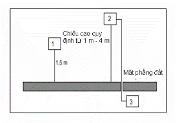
Figure C.1 - Arrangement of Measurement Number 1
1) Device Under Test
2) Measurement Antenna
3) Spectrum Analyzer or Measuring Receiver.
c) Rotate the transmitter 360 degrees around the vertical axis until the maximum signal is obtained.0 quanh trục thẳng đứng cho đến khi thu được tín hiệu lớn nhất.
Adjust the measurement antenna up or down within the specified height range until the maximum signal level is obtained. Record this value.
NOTE: The maximum value above may be smaller than the values obtained at heights outside the specified limits.
The measurement antenna does not need to be raised or lowered if the measurement is performed at the measurement position specified in Section B.1.2. This measurement is repeated for horizontal polarization.
C.2. Substitution Measurements
The signal generated by the device under test can be determined by using substitution measurements, in which a known signal source replaces the device under test, see Figure C.2.
It is best to perform substitution measurements in an anechoic chamber. For other measurement positions, adjustments may be necessary, see Appendix B.
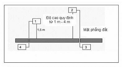
Figure C.2 - Arrangement of Measurement Number 2
1) Substitute Antenna
2) Measurement Antenna
3) Spectrum Analyzer or Selective Voltmeter
4) Signal Generator
a) Using the arrangement of measurement number 2, the substitute antenna will replace the transmitter antenna at the same position and vertical polarization. The frequency of the signal generator is tuned to the measurement frequency. The measurement antenna is adjusted up or down to ensure that the maximum signal is still received. The input signal level of the substitute antenna is adjusted until it equals or reaches a predetermined relative level compared to the known signal level at the measuring receiver;
- The measurement antenna does not need to be raised or lowered if the measurement is performed at the measurement position specified in Section B.1.2;
- The radiated power is equal to the power generated by the signal generator, increased by a known amount if necessary, after correction for the gain of the substitute antenna and cable loss between the signal generator and the substitute antenna.
b) This measurement is repeated for horizontal polarization.
QCVN 110:2017/BTTTT was compiled by the Post and Telecommunications Science and Technology Institute, reviewed by the Department of Science and Technology, and promulgated along with Circular No. 24/2017/TT-BTTTT dated October 17, 2017.
[1] ETSI TR 102 555: "Electromagnetic Compatibility and Radio Spectrum Matters (ERM); Technical Characteristics of Multiple Gigabit Wireless Systems in the 60 GHz Range System Reference Document".
[2] Directive 98/34/EC of the European Parliament and of the Council of 22 June 1998 laying down a procedure for the provision of information in the field of technical standards and regulations.
[3] IEEE 802.15.3c: "IEEE Standard for Information Technology - Specific Requirements - Part 15: Wireless Personal Area Networks with Millimeter Wave Alternative Physical Task Group 3c (TG3c)".
[4] ECMA TC48, High Rate Short Range Wireless Communications.
[5] ERC Recommendation 70-03 (Tromsø 1997 and subsequent amendments): "Related to the Use of Short Range Devices (SRD)".
[6] ETSI EG 201 399: "Electromagnetic Compatibility and Radio Spectrum Matters (ERM); A Guide to the Production of Harmonized Standards for Application under the R&TTE Directive".
[7] Commission Decision 2006/771/EC of 9 November 2006 on harmonization of the radio spectrum for use by short-range devices.
[8] Commission Decision 2010/368/EU of 30 June 2010 amending Decision 2006/771/EC on harmonisation of the radio spectrum for use by short-range devices.
[9] Directive 98/48/EC of the European Parliament and of the Council of 20 July 1998 amending Directive 98/34/EC laying down a procedure for the provision of information in the field of technical standards and regulations.
[10] ITU-R Recommendation M.2003-0: Multiple gigabit wireless systems in frequencies around 60 GHz, 2012.
Original document (PDF)
Download
Relations map
Click a document to open. A red border = a relation that changes validity.
Translations
This document is available in the following languages: