
These technical regulations specify electromagnetic compatibility (EMC) requirements for cable television, audio, and interactive service networks. They include maximum external field strength requirements within different frequency bands and carrier-to-noise ratios necessary to ensure signal quality. The regulations also provide specific measurement methods for both external EMC and system immunity.
적용 범위
These regulations apply to cable television, audio, and interactive service network operators within the territory of Vietnam.
핵심 사항
- Maximum external field strength outside the cable network is specified in Table B.1.
- Carrier-to-noise ratio requirements to ensure signal quality are set out in Table B.2.
- Methods for measuring external EMC and system immunity are detailed in Appendix B.
- Frequency bands and radio services are listed in Appendix C.
- Refer to international documents such as IEC, ITU-T, ITU-R to ensure compliance with international standards.
🌐 이 문서의 사회적 영향
- Minimize interference between radio devices and cable network systems.
- Ensure the quality of terrestrial digital television DVB-T2 signals at the reception point according to QCVN 83:2014/BTTTT.
- Comply with national radio frequency spectrum planning as issued by Decision No. 71/2013/QĐ-TTg and amended by Decision No. 02/2017/QĐ-TTg.
❓ 자주 묻는 질문
Which frequency bands does this regulation apply to?
This regulation applies to frequency bands from 30 MHz to 3500 MHz, including those designated for terrestrial digital television DVB-T2.
What is the maximum external field strength outside the cable network?
According to Table B.1 in the regulation, the maximum external field strength outside the cable network ranges from 0.15 MHz to 3500 MHz is 106 dBµV/m and from 694 MHz to 862 MHz is 120 dBµV/m.
How is external EMC measured?
External EMC measurement methods are detailed in Appendix B, including the use of specialized measurement equipment and antenna position changes to determine the level of interfering fields.
전문
|
MINISTRY OF INFORMATION AND COMMUNICATION |
SOCIALIST REPUBLIC OF VIET NAM Independence - Freedom - Happiness |
|
Number: 14/2021/TT-BTTTT |
Hanoi, October 29, 2022 |
CIRCULAR
Issuing the "National Technical Regulation on Electromagnetic Compatibility of Cable Networks for Distribution of Television Signals, Sound, and Interactive Services"
cable distribution of television signals, audio, and interactive services
Pursuant to the Law on Standards and Technical Regulations dated June 29, 2006;
Pursuant to the Law on Telecommunications dated November 23, 2009;
WHEREAS, the Law on Radio Frequency Spectrum dated November 23, 2009;
WHEREAS, Decree No. 127/2007/NĐ-CP dated August 1, 2007 of the Government detailing and guiding the implementation of certain provisions of the Law on Technical Standards and Regulations;
Pursuant to Decree No. 78/2018/ND-CP dated May 16, 2018 of the Government amending and supplementing certain articles of Decree No. 127/2007/NĐ-CP dated August 1, 2007 of the Government detailing the implementation of certain provisions of the Law on Standards and Technical Regulations;
Pursuant to Decree No. 17/2017/NĐ-CP dated February 17, 2017, issued by the Government, on the functions, tasks, powers, and organizational structure of the Ministry of Information and Communications;
At the proposal of the Director of the Science and Technology Department,
The Minister of Information and Communications issues this Circular stipulating the National Technical Regulation on Electromagnetic Compatibility of Cable Networks for Distribution of Television Signals, Sound, and Interactive Services.
Article 1. Attached herewith is the National Technical Regulation on Electromagnetic Compatibility of Cable Networks for Distribution of Television Signals, Sound, and Interactive Services (QCVN 71:2021/BTTTT).
Article 2. Effective Date
1. This Circular takes effect from July 1, 2022.
2. The National Technical Regulation on Electromagnetic Compatibility (EMC) of Cable Networks for Distribution of Television Signals, designated QCVN 71:2013/BTTTT, as stipulated in Clause 3, Article 1 of Circular No. 16/2013/TT-BTTTT dated July 10, 2013 of the Minister of Information and Communications, ceases to be effective from July 1, 2022.
Article 3. The Heads of the Office, Directors of the Science and Technology Department, Heads of agencies and units under the Ministry of Information and Communications, Directors of Provincial Departments of Information and Communications, and organizations and individuals related thereto shall be responsible for implementing this Circular.
|
Place of receipt: - Prime Minister, Deputy Prime Ministers (for circulation); - Ministries, agencies equivalent to ministries, and government agencies; - Provincial People's Councils, Provincial People's Committees; - Central Party Office and Party Committees; - National Assembly's Office; - President's Office; - Supreme People's Court; - Supreme People's Procuracy; - Provincial Departments of Information and Communications; - Legal Documents Supervision Bureau (Ministry of Justice); - Official Gazette, Government Electronic Portal; - Ministry of Information and Communications: Ministers, Deputy Ministers, departments and units under the Ministry, the Ministry's electronic portal; - To be filed: VT, KHCN (250). |
THE MINISTER
(Signed) Nguyen Manh Hung |
|
SOCIALIST REPUBLIC OF VIET NAM
QCVN 71:2021/BTTTT
AMENDMENT 1:2025 QCVN 07:2023/BXD ON ELECTROMAGNETIC COMPATIBILITY OF CABLE NETWORKS FOR DISTRIBUTION OF TELEVISION SIGNALS, SOUND AND INTERACTIVE SERVICES HANOI -
National technical regulation 1... GENERAL PROVISIONS... 2
1.1... SCOPE... 2 2021 |
|
|
Table of Contents
1.2... APPLICABILITY... 2
1.3... REFERENCED DOCUMENTS... 2
1.4... DEFINITIONS... 2
1.5... ABBREVIATIONS... 2
2... TECHNICAL REQUIREMENTS... 2
2.1... TECHNICAL REQUIREMENTS... 2
2.1.1. RADIATED EMISSIONS FROM DIGITAL, WIDE BAND SIGNALS... 2
2.1.2. RADIATED EMISSIONS FROM NARROW BAND SIGNALS... 2
2.2... MEASUREMENT METHODS... 2
2.2.1. GENERAL PROVISIONS... 2
2.2.2. FIELD STRENGTH MEASUREMENT METHODS... 2
2.2.3. MEASUREMENT METHODS FOR CARRIER FREQUENCY OFFSETS... 2
3... MANAGEMENT PROVISIONS... 2
4... RESPONSIBILITIES OF ORGANIZATIONS AND INDIVIDUALS... 2
5... IMPLEMENTATION ORGANIZATION... 2
ANNEX A (REGULATORY) Measurement at distances other than the standard 3 meters... 2
ANNEX B (REFERENCE) Immunity of cable networks... 2
ANNEX C (REFERENCE) Radio frequency bands and radio services... 2
ANNEX D (REFERENCE) Hybrid Fiber-Coaxial (HFC) cable network system model... 2
LIST OF REFERENCE DOCUMENTS... 2
QCVN 71:2021/BTTTT replaces QCVN 71:2013/BTTTT.
QCVN 71:2021/BTTTT was compiled by the Frequency Management Agency, submitted for review by the Science and Technology Department, examined by the Ministry of Science and Technology, and issued together with Circular No. /2021/TT-BTTTT dated / month / year 2021.
|
|
Foreword
ON ELECTROMAGNETIC COMPATIBILITY OF CABLE NETWORKS FOR DISTRIBUTION OF TELEVISION SIGNALS, SOUND AND INTERACTIVE SERVICES
on electromagnetic compatibility (EMC) of cable networks for distribution of
|
|
|
|
AMENDMENT 1:2025 QCVN 07:2023/BXD
television, sound and interactive services
1... GENERAL PROVISIONS
National technical regulation
1.1... SCOPE
This national technical regulation specifies requirements for radiated electromagnetic interference from cable networks used for transmitting television signals, sound, and interactive services within the frequency band from 0.15 MHz to 3.5 GHz in Vietnam.
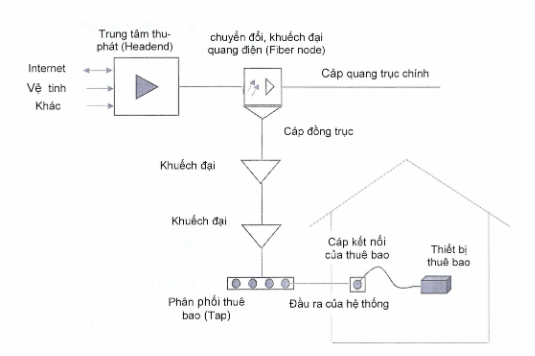
Cable networks starting from the headend to the system outlet (illustrated in Annex D) must comply with this regulation unless otherwise specified.
The application of this regulation ensures that cable networks can operate concurrently with radio services such as safety, broadcasting, air mobile, air navigation, ground mobile (including cellular mobile networks), and other services as defined in the National Radio Frequency Spectrum Plan without causing interference. Frequency ranges of some services are listed in Annex C.
1.2... APPLICABILITY
This technical regulation applies to organizations and enterprises providing cable television services in Vietnam.
1.3... REFERENCED DOCUMENTS
IEC 60728-12:2017 Cable networks for television signals, sound signals and interactive services – Part 12: Electromagnetic compatibility of systems.
1.4... DEFINITIONS
1.4.1... ELECTROMAGNETIC RADIATION
- The phenomenon where energy in the form of electromagnetic waves emanates from a source into space;
- Energy transmitted through space in the form of electromagnetic waves.
NOTE: Broadly speaking, the concept of "electromagnetic radiation" may also include the phenomenon of induction.
1.4.2... INTERACTIVE SERVICES
Services involving two-way communication between the headend and subscribers (for example, internet service).
1.4.3... IMMUNITY TO DISTURBANCES
The ability of a component, device, or system to perform its intended function without degradation when subjected to electromagnetic disturbances (hereinafter referred to as immunity).
1.4.4... ELECTROMAGNETIC DISTURBANCE
Any electromagnetic phenomenon capable of degrading the performance of a component, device, or system.
1.4.5... ELECTROMAGNETIC INTERFERENCE (EMI)
The degradation of the performance of a device, transmission channel, or system due to electromagnetic interference.
1.4.6... OPERATING FREQUENCY RANGE
The bandwidth of the desired signal for which a device is designed to operate.
The degradation of the performance quality of a device, transmission channel, or system due to electromagnetic interference.
1.4.6 Operating Frequency Range
The bandwidth of the desired signal for which the equipment is designed to operate.
1.4.7. Carrier-to-interference ratio (carrier-to-interference ratio [C/I])
The ratio between the carrier wave and the total interference power including both internal system interference and interference from other systems.
1.4.8. Headend
A system of equipment connecting antennas or other signal sources to the rest of the cable network, through which signals are distributed.
NOTE: The end-of-cable headend may include antenna amplifiers, frequency converters, combiners, splitters, and signal generators.
1.4.9. System outlet
Equipment for connecting a subscriber's cable to the cable network.
1.4.10. Disturbance level
The level of electromagnetic field signal causing interference at a specific location due to combined interference sources.
1.4.11. Degradation of performance
Unwanted appearance in the quality of operation of a component, device, or system compared to expected performance.
NOTE: The concept of "degradation" may apply to either temporary or permanent damage.
1.4.12. Subscriber’s feeder
Cable connecting a subscriber to the system outlet, or if there is none, directly to the subscriber equipment.
NOTE: The subscriber connection cable may include filters and baluns.
1.4.13. Receiver lead
The output connection of the network to the subscriber equipment.
1.4.14. Digital, broadband signal
In this Standard, digital, broadband signal refers to digital television or internet signals.
1.4.15. Narrowband signal
Remaining components such as analog television broadcasts...
1.5. Abbreviations
|
AM |
Amplitude Modulation |
Article |
|
BPF |
Band Pass Filter |
Band-pass filter |
|
CATV |
Community Antenna Television |
Cable television |
|
DSC |
Distress, Safety and Calling |
Selective calling |
|
EMC |
Electromagnetic Compatibility |
ElectroMagnetic Compatibility |
|
EMI |
Electromagnetic Interference |
Electromagnetic interference |
|
EPIRB |
Emergency Position Indicating Radiobeacons |
Emergency position indicating radio beacons |
|
FM |
Frequency Modulation |
Frequency modulation |
|
HFC |
Hybrid fiber-coax network |
Hybrid fiber-coaxial network |
|
ILS |
Instrument Landing System |
Instrument landing system |
|
ITU-R
|
International Telecommunication Union - Radiocommunication |
International Telecommunication Union - Radiocommunication Sector |
|
LNA |
Low Noise Amplifier |
Low-noise amplifier |
|
MATV |
Master Antenna Television Network |
Master antenna television network |
|
RF |
Radio Frequency |
Radio Frequency |
|
RMS |
Root Mean Square |
Root mean square |
|
SMATV |
Satellite Master Antenna Television Network |
Satellite master antenna television network |
|
TV |
Television |
Television receiver |
|
VSB |
Vestigial Side Band |
Vestigial sideband |
2. TECHNICAL REQUIREMENTS
2.1. Technical Requirements
2.1.1. Broadband digital signal radiation
The maximum allowable radiation levels for broadband digital signals are specified in Table 1, applicable according to the measurement method described in Section 2.2 as follows:
Table 1 - Limits on broadband digital signal radiation
|
Frequency band MHz |
Radiation field intensity limit @3m, measured over an 8 MHz channel width dBµV/m |
Separation mode |
|
30 to 950 |
37 |
RMS |
|
950 to 2500 |
43 |
RMS |
|
2500 to 3500 |
45 |
RMS |
2.1.2. Narrowband signal radiation
If the cable network radiation includes narrowband signal radiation, then the maximum allowable radiation levels for narrowband signals are specified in Table 2, applicable according to the measurement method described in Section 2.2 as follows:
Table 2 - ofLimit on narrowband signal radiation Radiation field intensity limit @3m
|
Frequency band MHz |
Measured bandwidth dBµV/m |
100 kHz |
Separation mode |
|
30 to 950 |
27 |
1 MHz |
RMS |
|
950 to 2500 |
43 |
2.2. Measurement Methods |
RMS |
|
2500 to 3500 |
45 |
2.2. Measurement Methods |
RMS |
These measurement methods describe procedures for measuring the radiation levels generated by the cable network.
Measurements include essential measurement parameters and conditions to evaluate electromagnetic compatibility issues between the cable network and wireless telecommunications networks or other electrical/electronic devices. During testing, the cable network must operate under normal operating conditions as intended for that network.
2.2.1. General Provisions
When measuring the cable network, terminal equipment may be connected. Testing the cable network against relevant limits may require disconnecting terminal equipment. If limits are exceeded, individual parts of the network (such as terminal equipment, outdoor satellite receivers, distribution installations, etc.) may need to be tested subsequently to identify which part of the network is not within limits.
Measurement frequencies must be selected to ensure they are not affected by strong radio emissions in the survey area, such as terrestrial digital television, mobile communications, etc., to avoid anomalies in measurement results.
The number of measurement frequencies must be chosen to adequately assess all radiated signal components across the entire operational frequency range of the cable network.
Measurement points within a geographic area of the cable network must be selected to include high-risk radiation points (points with active network equipment such as optical-electrical converters, amplifiers, etc.) to fully evaluate potential electromagnetic compatibility issues of the cable network.
Maximum allowable radiation levels are specified in Section 2.1.
2.2.2. Field Intensity Measurement Method
Figure 1 - Illustration of field intensity measurement setup
2.2.2.1. Measurement Equipment Requirements
- To measure radiation from a cable network, the measurement system includes a receiver connected to a directional antenna to measure field intensity;
- An appropriately calibrated receiver capable of measuring channel power and appropriate separation modes;
- A calibrated antenna (antenna with determined parameters such as gain, antenna factor, impedance);
- Coaxial cable with frequency-dependent loss characteristics determined;
- Where necessary, a low noise amplifier (LNA) and a calibrated band-pass filter (BPF) covering the required frequency range may be used;
- This standard specifies radiation levels based on field intensity at a distance of 3 meters from the source of radiation. In special cases (where standard 3-meter measurements cannot be made), alternative measurement distances as specified in Appendix A may be used.
2.2.2.2. Procedure for Measuring Field Intensity
It must be ensured that the cable network is operating with normal signal levels.
It is necessary to ensure that the cable network is operating at normal signal levels.
Where it can be determined that the radiation levels of the channels within the frequency band to be surveyed are equivalent, the radiation of some channels in the survey frequency band may be measured to representatively assess the overall level.
Set the measuring instrument in the wave detector (detector) RMS mode and display (trace) AVERAGE mode. For digital signal radiation, set the channel power measurement mode with a bandwidth of 8 MHz to calculate the total radiated power. In cases where the cable network includes digital signals with channel spacing other than 8 MHz, measure the total radiated power within 8 MHz at the center frequency of the surveyed channel and evaluate according to the limits in Table 1.
For narrowband signal radiation, set the resolution bandwidth (RBW) and evaluate according to the limits in Table 2.
Measurement distance For coal-fired thermal power plants where the enterprise holds 100% of the registered capital and uses 100% of its own capital to invest in the project approved by the competent authority, E is determined as 100%; is determined as follows: It is the distance from the point to be surveyed on the cable network to the reference point of the measuring antenna.
For a specific measurement point, the direction, height, and polarization of the measuring antenna must be changed to obtain the maximum field strength value.
NOTE 1: The change in antenna parameters, particularly the antenna height, depends on the measurement frequency. When the calibrated size of the measuring antenna does not match reality, using a calibrated loop antenna is very useful.
If the measuring instrument provides results in the form of input voltage levels, the field strength level can be calculated and converted using the formula:
(1)
Where:
is the field strength of the radiation, unit dBµV/m;
is the input voltage level of the receiver dBµV (50Ω impedance);
is the cable loss in dB;
is the antenna factor provided by the manufacturer's technical documentation or the antenna calibration process, unit dB/m. For an antenna with 50Ω impedance, the antenna factor can be determined through the antenna gain according to the formula:
(2)
Where:
g is the gain of the measuring antenna, unit dBi;
f is the measurement frequency, unit MHz;
2.2.3 Subcarrier Measurement Method
The subcarrier measurement method is used when direct measurement of digital, broadband signal radiation is not possible (for example, when the field strength of the radiation is lower than the receiver sensitivity). This is due to the reduced sensitivity at the receiver input caused by the decrease in signal-to-noise ratio compared to the expanded bandwidth required for broadband signal measurement.
2.2.3.1 Radiation Level and Adjustment
To evaluate the leakage radiation level of digital, broadband signals using the subcarrier measurement method, an unmodulated carrier signal of the form sin can be inserted between the digital, broadband signals. This subcarrier is set such that the signal level is measured with a measurement bandwidth of 200 Hz, matching the previously measured value of the digital, broadband signal.
If necessary, the subcarrier can be supplied at a higher level than the desired level of the digital, broadband signal. It is important to appropriately consider the limitations of the system. The determination of the leakage field strength of the digital, broadband signal is specified in 2.2.3.2.
In all cases, the use of a subcarrier will need to be coordinated with the network operator.
2.2.3.2 Determination of Radiated Field Strength
When the levels of the subcarrier and the digital, broadband signal have been established according to 2.2.3.1, the measurement results of the subcarrier at relevant measurement points provide the field strength directly or indirectly influencing the voltage at the receiver input.
If the subcarrier is fed into the cable network at a higher level than the desired digital, broadband signal, the value of the leaking digital, broadband signal will be equal to the measured field strength of the subcarrier minus the difference between the subcarrier level and the aforementioned digital, broadband signal level.
(3)
Where:
is the field strength of the leaking signal to be measured (dBµV/m);
is the leakage field strength of the subcarrier (dBµV/m);
is the power of the subcarrier injected into the cable network (dBm);
is the power of the digital, broadband signal to be measured (dBm).
3 MANAGEMENT PROVISIONS
Electromagnetic interference emissions from cable networks transmitting image, sound, and interactive services within the scope regulated under 1.1 must comply with the requirements stipulated in this Standard.
4 RESPONSIBILITIES OF ORGANIZATIONS AND INDIVIDUALS
4.1. Organizations and enterprises providing cable television services are responsible for ensuring that the cable distribution network for television signals complies with this Standard during design, installation, operation, maintenance, and coordination with related parties in resolving interference from cable television networks affecting the operations of other networks and services.
4.2. Organizations and enterprises providing cable television services are responsible for ensuring the immunity capability of their own cable networks (see Appendix B).
4.3. Organizations and enterprises providing cable television services are responsible for implementing conformity declarations in accordance with the regulations and guidelines of the Ministry of Information and Communications and are subject to regular and spot inspections by state management agencies in accordance with current regulations.
4.4. The Telecommunications Regulatory Authority is responsible for receiving declarations of conformity, managing and guiding, and inspecting conformity declarations. The procedures for declaring conformity are stipulated in Circular No. 28/2012/TT-BKHCN dated December 12, 2012, issued by the Minister of Science and Technology regarding declarations of conformity and compliance assessment methods with standards and technical regulations.
5 IMPLEMENTATION
5.1. The Telecommunications Regulatory Authority, the Radio Frequency Management Agency, and Provincial Departments of Information and Communications are responsible for guiding and organizing the implementation of management of organizations and enterprises in accordance with this Standard.
5.2. This Standard replaces National Technical Regulation QCVN 71:2013/BTTTT "National Technical Regulations on Electromagnetic Compatibility (EMC) of Cable Distribution Networks for Television Signals."
5.3. In cases where the provisions set forth in this Standard are changed, supplemented, or replaced, they shall be implemented according to the new document.
5.4. During the implementation of this Standard, if any issues arise or difficulties occur, organizations and individuals should report them in writing to the Ministry of Information and Communications (Science and Technology Department) for guidance and resolution.
ANNEX A
Product Name, Goods According to QCVN
Measurement at distances other than the standard 3 meters
A.1 Measurement at distances less than 3 meters
If measurement is conducted at a distance less than 3 meters, the distance to the cable network is determined by the geometric opening of the loop antenna.
If the standard measurement at a distance of 3 meters cannot be achieved (for example, in the limited space of alleys), a shorter measurement distance may be used. However, the minimum measurement distance must ensure at least 1 meter. In this case, the measurement result will be calculated and adjusted according to formula A-1.
(A-1)
Where:
is the measured result, unit dBµV/m;
is the adjusted measured result, unit dBµV/m;
is the measurement distance, unit m;
is the standard measurement distance (3 m).
A.2. Measurement at distances greater than 3 m
If it is not possible to perform the measurement at the standard distance of 3 meters, measurements can be conducted at distances greater than 3 meters. Two measurement points must be determined on the axis perpendicular to the direction of the cable network to be measured. The distance between the two measurement points should be as large as possible. The field strength level is measured as described in 2.2.2. The measurement results must be expressed in units of dBµV/m and plotted on a logarithmic graph of distance. The straight line connecting the measurement results shows the reduction in field strength along the measurement direction. If the reduction in field strength cannot be determined, additional measurements must be performed. The standard field strength level must be read from the graph using the connecting lines.
Provisions on the HS Code of Terrestrial Mobile Radio Equipment and Terrestrial Radio Relay Equipment
(For reference)
Immunity of the cable network
B.1. Technical requirements
The immunity limit (Table B.1) defines the standard external field strength level outside the cable network. With that value, the carrier-to-noise ratio specified in Table B.2 (quality requirements) must be obtained for the desired signal channel at any point within the cable network.
Table B.1 – Maximum field strength
|
Frequency Band (MHz) |
Field Strength (dBµV/m) |
|
0.15 to 3 500 |
106 |
|
694 to 862 |
120a |
|
a in the case where the desired signal uses digital modulation. |
|
The quality requirements for the cable network correspond to the AM-VSB-TV or QAM-DVB signals in the frequency range from 30 MHz to 1 000 MHz and FM-TV signals in the frequency range from 950 MHz to 3 500 MHz. When the cable network distributes other signals (such as digitally modulated signals), due to the lower required carrier-to-noise ratios for these signals, the immunity capability of the cable network is higher.
The measurement method is specified in B.2.
Table B.2 – Required carrier-to-noise ratio
|
Frequency Range Applied (MHz) |
Carrier-to-Noise Ratio (dB) |
|
30 to 1 000 |
≥ 57 (AM) ≥ 35 (64/256 QAM) |
|
950 to 3 500 |
≥ 33 (FM) ≥ 13 (QPSK) |
B.2. Measurement Method
In the presence of interference, the carrier-to-noise ratio will be measured at the affected outputs.
First, the desired signal level must be measured at each affected channel output. Then, the cable network must be disconnected from the interface points or antennas of the system. Open ports must be terminated with a 75 Ohm load. The signal level at each output is measured using a receiver in peak mode, taking into account the bandwidth of the desired signal. It must be ensured that the measuring instrument is well impedance-matched with the network and that reflection losses can be considered.
The difference between the desired signal level and the interference signal level is the carrier-to-noise ratio which must meet the requirements set out in Table B.2.
If the carrier-to-noise ratio is equal to or greater than the nominal value, the network meets the requirements. If the carrier-to-noise ratio is less than the required ratio, additional measurements must be performed. All distributions installed outside the system output ports (receiver cables, receivers, subscriber installations) will be disconnected from the network for testing. In most cases, interference is caused by these components. Interference levels must be remeasured. After measurement, normal operating conditions of the network will be restored.
If these test methods do not yield better carrier-to-noise ratios, it will be considered that interfering signals have entered the cable network. In this case, the field strength of the external signals near the building will be measured at a point adjacent to the assumed point of interference entry.
The maximum field strength is determined by changing the antenna position. As per the limits in Table B.1, the carrier-to-noise ratios must meet the requirements in Table B.2.
If the interference-causing field strength is equal to or lower than these values, the network does not meet the requirements and the operator must take measures to improve the network's immunity capability.
If the measured interference-causing field strength exceeds this value, the network requirements do not correspond to the requirements of other radio services (high-power transmitters). Solutions to this problem must be resolved by regulatory authorities and radio service operators.
Annex C
(For reference)
Frequency Bands and Radio Services
|
Frequency band (MHz) |
Protected Radio Systems |
|
74.8 to 75.2 |
Space-based air navigation radio system; Radio landing system ILS |
|
108 to 117.975 |
Air navigation radio system |
|
121.450 to 121.550 |
Safety and rescue (EPIRPs) |
|
156,525 |
Rescue DSC |
|
156.7625 to 156.8375 |
International maritime distress and safety communication |
|
328.6 to 335.4 |
Air navigation radio system |
|
406.0 to 406.1 |
Emergency Position Indicating Radio Beacon (EPIRB) |
|
703 to 733 and 758 to 788 |
Mobile cellular information |
|
824 to 835 |
Mobile cellular information |
|
869 to 915 |
Mobile cellular information |
|
925 to 960 |
Mobile cellular information |
|
1710 to 1785 and 1805 to 1880 |
Mobile cellular information |
|
1920 to 1970 and 2110 to 2170 |
Mobile cellular information |
|
2300 to 2400 |
Mobile cellular information |
|
2500 to 2690 |
Mobile cellular information |
Appendix D
(For reference)
High-Frequency Cable Network System Model
Bibliography
[1] IEC 60728-12:2017 Edition 2.0 (06/2017) Cable networks for television signals, sound signals and interactive services – Part 12: Electromagnetic compatibility of systems;
[2] ITU-T K.106 (03/2015) Techniques to mitigate interference between radio devices and cable or equipment connected to wired broadband networks and cable television networks;
[3] ITU-R BT.2339-0 (11/2014) Co-channel sharing and compatibility studies between digital terrestrial television broadcasting and international mobile telecommunication in the frequency band 694-790 MHz in the GE06 planning area;
[4] ICAO Doc 9718 AN/957 (2018) Handbook on Radio Frequency Spectrum Requirements for Civil Aviation - Volume I ICAO spectrum strategy, policy statements and related information;
[5] Title 47: Telecommunication (FCC Rules), Part 76: Multichannel Video and Cable Television Service.
[6] Recommendation ITU-R F.1336-5 (01/2019) Reference radiation patterns of omnidirectional, sectoral and other antennas for the fixed and mobile services for use in sharing studies in the frequency range from 400 MHz to about 70 GHz.
[7] QCVN 72:2013/BTTTT, National technical regulation on electromagnetic compatibility (EMC) of equipment in cable television distribution systems.
[8] QCVN 83:2014/BTTTT, National technical regulation on signal quality of ground digital television DVB-T2 at the receiving point.
[9] Recommendation ITU-R BT.2033-1 (2015) Planning criteria including protection ratios, for second generation of digital terrestrial television broadcasting systems in the VHF/UHF bands.
[10] Report ITU-R BT.2254-4 (10/2020) Frequency and network planning aspects of DVB-T2.
[11] Recommendation ITU-R BT.419-3 Directivity and polarization discrimination of antennas in the reception of television broadcasting.
[12] ITU-R The Handbook on Spectrum Monitoring (2011).
[13] Decision No. 71/2013/QĐ-TTg dated November 21, 2013 of the Prime Minister promulgating the National Radio Frequency Band Plan.
[14] Decision No. 02/2017/QĐ-TTg dated January 17, 2017 of
the Prime Minister amending and supplementing the National Radio Frequency Band Plan issued together with Decision No. 71/2013/QĐ-TTg dated November 21, 2013 of the Prime Minister.
원본 문서(PDF)
관계도
문서를 클릭하면 열립니다. 빨간 테두리=효력을 변경하는 관계.
번역본
이 문서는 다음 언어로 제공됩니다: