
Circular No. 26/2015/TT-BTTTT promulgates the National Technical Regulation on wireless audio equipment with frequency range from 25 MHz to 2000 MHz, applicable to organizations and individuals producing and trading such equipment throughout the territory of Vietnam. The regulation specifies detailed technical requirements regarding radiated power, channel bandwidth, frequency deviation, spurious emissions, etc., with specific non-compliance levels.
Đối tượng áp dụng
Organizations and individuals, both domestic and foreign, producing and trading wireless audio equipment with frequency range from 25 MHz to 2000 MHz throughout the territory of Vietnam.
Các điểm cốt lõi
- Equipment must meet the technical requirements of the regulation at all intended channels, with a frequency deviation of ±75 kHz for low-power Band II equipment.
- Effective radiated power shall not exceed 3 nW e.r.p at all frequencies except for the carrier frequency of the transmitter and modulation sidebands, or the maximum field strength radiation level is 30 dBuV/m at the measurement point 10 meters away.
- Channel bandwidth must be within the specified limits, with frequency deviation not exceeding ±5% for frequencies from 300 Hz to 6 kHz and ±3 dB for frequencies from 6 kHz to 25 kHz.
- Spurious emissions shall not exceed the prescribed limits, with the maximum effective radiated power being 3 nW (-55.2 dBm) at all frequencies except for the carrier frequency of the transmitter and modulation sidebands.
- The transmitter's downtime must be less than 1 minute.
🌐 Tác động xã hội từ văn bản này
- Positive impact: Ensuring the quality of wireless audio signals, reducing interference and spurious emissions, enhancing information security.
- Negative impact: May increase production costs for businesses due to stricter technical requirements.
❓ Câu hỏi thường gặp
What is the regulation regarding the effective radiated power of low-power Band II equipment?
Effective radiated power shall not exceed 3 nW e.r.p at all frequencies except for the carrier frequency of the transmitter and modulation sidebands, or the maximum field strength radiation level is 30 dBuV/m at the measurement point 10 meters away.
How is the frequency deviation of the equipment regulated?
Frequency deviation shall not exceed ±5% for frequencies from 300 Hz to 6 kHz and ±3 dB for frequencies from 6 kHz to 25 kHz.
How long must the transmitter's downtime be?
The transmitter's downtime must be less than 1 minute to eliminate input audio signals.
What is the regulation regarding the effective radiated power of low-power Band II equipment?
Effective radiated power shall not exceed 3 nW e.r.p at all frequencies except for the carrier frequency of the transmitter and modulation sidebands, or the maximum field strength radiation level is 30 dBuV/m at the measurement point 10 meters away.
What is the regulation regarding the carrier power of low-power Band II equipment?
Carrier power shall not exceed the limit in Table 7, with this power level having to be within ±3 dB of the power level announced by the testing entity.
Toàn văn
CIRCULAR
Issuing "Article 24national technical regulation on wireless audio equipment
frequency range from 25 MHz to 2000 MHz
-------------------------------------
Pursuant to the Law on Technical Standards and Regulations dated June 29, 2006;June 2024;Article 6 2006;
Pursuant to the Law on Telecommunications dated November 23, 2009;
Pursuant to DecreeNo. 127/2007/NĐ-CP dated August 1, 2007 of LAW the Government stipulating theANNEX I.A[31] Pursuant to Decree No. 48/2015/NĐ-CP dated May 15, 2015 of the Government detailing certain provisions of the Higher Education LawANNEX I.A[31] Pursuant to Decree No. 11/2020/NĐ-CP dated October 15, 2020 of the Government detailing implementation of certain provisions and measures for organizing the implementation of the Law on Petitions;No. The Government shall define the functions, tasks, chuẩn contents and Technical Regulations;
Pursuant to Decree No. 132/2013/NĐ-CP dated October 16, 2013 of Pursuant to Decree No. 60/2021/NĐ-CP dated June 21, 2021, which establishes the financial autonomy mechanism for public service organizations, as amended and supplemented by Decree No. 111/2025/NĐ-CP dated May 22, 2025; regulation on shipborne watchkeeping receivers for reception of Digital Selective Calling operating in the MF, MF/HF and VHF bands of maritime mobile
Pursuant to the proposal of the Director of the Department of Ethnic Affairs and Religion Propaganda;on the Minister of Science and Technology,
The Minister of Information and Communications issues this Circular stipulating REGULATION chuẩn national technical regulation on wireless audio equipment in the frequency range fromầ25 MHz to 2000 MHz.
Article 1. Issued herewith is the National Technical Regulation on Wireless Audio Equipment in the Frequency Range from 25 MHz to 2000 MHz (QCVN 91:2015/BTTTT).
Article 2. This Circular takes effect from April 1, 2016.
Article 3. The Head of the Office, the Director of the Department of Science and Technology, Heads of agencies and units under the Ministry of Information and Communications, Directors of Provincial Departments of Information and Communications, and organizations and individuals related thereto shall be responsible for implementing this Circular./.
|
THE MINISTER (Signed)
Nguyen Bac Son |
NATIONAL TECHNICAL REGULATION ON WIRELESS AUDIO EQUIPMENT IN THE FREQUENCY RANGE FROM 25 MHz TO 2000 MHz
National technical regulation on cordless audio devices in the range 25 MHz to 2000 MHz
Chapter 1. GENERAL PROVISIONS
1.1. Scope of Application
This regulation applies to wireless audio devices operating in the frequency range of 25 MHz to 2000 MHz as follows:
- Wireless headphones:
- Wireless speakers,
- Analog modulation personal monitoring devices with a bandwidth of 300 kHz or digital FDMA modulation devices with a bandwidth of 300 kHz, 600 kHz, 1200 kHz;
- Wireless audio devices in vehicles;
- Personal wireless devices;
- Devices in multi-channel wideband systems;
- Low-power devices in Band II frequency range from 87.5 MHz to 108 MHz (Band II reserved for broadcasting services) using analog modulation with a bandwidth not exceeding 200 kHz.
1.2. Applicability
This regulation applies to organizations and individuals, both domestic and foreign, engaged in the production and business of devices within the scope of this regulation throughout the territory of Vietnam.
1.3. Referenced Documents
Recommendation ITU-R BS.559-2 (1990): "Objective measurement of frequency protection ratios in LF, MF and HF broadcasting."
IEC 60244-13 (1991): "Measurement methods for radio transmitters - Part 13: Performance characteristics for FM sound broadcasting transmitters."
ETSI TR 102 273 (all parts) (2001): "Electromagnetic compatibility and radio spectrum matters (ERM); Improvements to measurement procedures (using test sites) and associated measurement uncertainty assessment."
ANSI C63.5 (2006): "American National Standard for Antenna Calibration Used for Electromagnetic Interference Emission Measurements."
IEC 60489-3 (1988): "Measurement methods for radio equipment used in mobile service. Part 3: A3E or F3E transmitters."
1.4. Terms and Definitions
1.4.1. Allocated or applicable band (Băng tần phân chia hoặc bằng tần ứng dụng) Defined according to the national radio frequency spectrum planning.
1.4.2. Artificial antenna (Ăng ten giảȧ) An artificial load adjusted for radiation, having a nominal impedance equal to the high-frequency output impedance of the device under test. This impedance level is specified by the manufacturer.
1.4.3. Channel bandwidth (Băng thông kênh) The largest bandwidth that includes the necessary bandwidth of the transmitter.
1.4.4. Cordless (Không dây) Connection between two or more entities without physical connection. This regulation refers only to wireless systems operating at radio frequencies.
1.4.5. Integral antenna (Ăng ten tích hợp) An antenna designed as part of the device without using a standard connector and considered as part of the device.
1.4.6. Integral antenna for Band II LPD only (Ăng ten tích hợp cho thiết bị công suất thấp băng tần II) An antenna designed as a fixed part of the device and considered an integral part of the device.
1.4.7. Necessary bandwidth (Độ rộng băng tần cần thiết) The width of the frequency band sufficient to ensure the transmission of information at the required speed and quality under predetermined conditions.
1.4.8. Nominal channel frequency (Tần số kênh danh định) The frequency published by the manufacturer.
1.4.9. Occupied bandwidth (Độ rộng băng tần chiếm dụng) The width of the frequency band where the average power emitted below the lower limit and above the upper limit of the band equals a predetermined percentage of the total average power of the emission.
If not otherwise specified, the value of ẞ/2 is chosen as 0.5%.
1.4.10. Port (Công) Any point of connection on or inside the device under test (EUT) used to connect cables to the device or from the device.
1.4.11. Radiated measurements (Phép đo bức xạ) Measurements related to measuring absolute field radiation values.
1.4.12. Spurious emission (Phát xạ giả) Emission on one or more frequencies outside the necessary bandwidth, the levels of which may be reduced without affecting the corresponding information transmission. Spurious emissions include harmonic emissions, parasitic emissions, intermodulation products, and frequency conversion products, but do not include out-of-band emissions.
1.4.13. Band II low-power device (Thiết bị công suất thấp băng tần II) Short-range low-power FM transmitters operating in the FM band reserved for broadcasting services in the frequency range from 87.5 MHz to 108 MHz, used to provide a wireless connection between a personal audio device, including mobile phones and car entertainment systems or home entertainment systems.
λ Wavelength
dBc Decibel relative to carrier power
E Field strength
fc Carrier frequency
fo Operating frequency
ac Alternating current
B Channel bandwidth
BN Necessary bandwidth
CW Continuous wave
dc Direct current
e.r.p Effective radiated power
dBc
e.i.r.p Equivalent isotropic radiated power
EUT Equipment under test
FDMA Frequency division multiple access
FM Frequency modulation
HF High frequency
Bandwidth
LF Low frequency
LPD Low-power device
Necessary bandwidth — Necessary bandwidth
Continuous wave — Continuous wave
Direct current — Direct current
Effective radiated power — Effective radiated power
Equivalent Isotropically Radiated Power — Equivalent Isotropically Radiated Power
Equipment Under Test — Equipment Under Test
Frequency Division Multiple Access — Frequency Division Multiple Access
Frequency Modulation — Frequency Modulation
High Frequency — High Frequency
Low Frequency — Low Frequency
Low Power Device — Low Power Device
OATS Outdoor Measurement Site — Open Area Test Site
RBW Resolution Bandwidth — Resolution BandWidth
RF Radio Frequency — Radio Frequency
SINAD Signal-to-Noise-and-Distortion Ratio — (Signal + Noise + Distortion) over (Noise + Distortion)
SRD Short Range Device — Short Range Devices
Tx Transmitter — Transmitter
VBW Video Bandwidth — Video BandWidth
VSWR Voltage Standing Wave Ratio — Voltage Standing Wave Ratio
Chapter 2. TECHNICAL PROVISIONS
2.2. Requirements for ADSL end equipment (ATU-R) - type ADSL2
2.1.1. Requirements for Equipment to be Tested
The equipment to be tested must meet all requirements of this standard on all channels intended for operation.
The party with the equipment to be tested must have a testing procedure for the equipment.
The party with the equipment to be tested must clearly specify the frequency band that the equipment is permitted to operate within.
The party with the equipment to be tested must provide complete information related to the interface, any tools, and test connectors necessary for:
- Connection to a direct current power supply;
- Analog audio connection;
- Limiting transmitter deviation; and
- Setting input signal levels and input audio levels in normal operating mode instead of a 500 Hz (or 1 KHz for LPD band II) sine wave input signal. The manufacturer must announce the setting of other adjustment levels to avoid invalidating the tests.
In the case where low-power band II devices replace integrated devices, it is necessary to create a file of sine wave signals to stimulate the transmitter input. The amplitude of these signals may vary (but must be the same for each signal) to accurately adjust the carrier frequency deviation of the transmitter output ±75 kHz.
In addition to technical documentation, the party with the equipment to be tested must also provide an operator's manual containing similar content to the model equipment's manual.
To simplify and harmonize testing methods between manufacturers and testing laboratories, all measurements must comply with this standard for all models of equipment specified in Sections 2.1.1.1 through 2.1.1.6.2.
2.1.1.1. Selection of Equipment to be Tested
The party with the equipment to be tested must provide a sample of the equipment to be tested.
The equipment to be tested must be typical examples from the production model.
2.1.1.2. Definition of Calibration Band and Pre-set Channel Frequency Band
The calibration band is the frequency range in which the receiver or transmitter can be programmed and/or recalibrated to operate with a single-frequency oscillator without any physical changes to the circuitry except for replacing:
- Program memory ROMs.
- Crystals.
- Frequency-setting elements (in both receivers and transmitters). These elements cannot be adjusted by users.
The pre-set channel frequency band is the fixed frequency range defined by the manufacturer, allowing the receiver and transmitter to operate without reprogramming or recalibration.
When submitting equipment for conformity testing, the party with the equipment to be tested must notify the calibration bands of the receiver and transmitter. The party with the equipment to be tested must also provide the pre-set channel frequency bands of the receiver and transmitter (these two bands may differ).
For low-power (LPD) band II equipment, the transmitter frequency band must lie within the range from 87.6 MHz to 107.9 MHz.
2.1.1.3. Calibration Band
The calibration bands of the receiver and transmitter may be different but must fall within the specified frequency band.
2.1.1.4. Selection of Test Frequencies
The frequencies for testing are selected by the manufacturer in accordance with Sections 2.1.1.5 to 2.1.1.7. When selecting test frequencies, the manufacturer must ensure that the chosen frequencies lie within one or more national frequency bands.
For low-power band II equipment, the carrier frequency of the transmitter must lie within the range from 87.6 MHz to 107.9 MHz, and the frequency generating the highest radiated power must be selected.
2.1.1.4.1. Testing Single-Channel Equipment
Conduct full testing on one channel within B/2 around the center frequency of the calibration band (B is the channel bandwidth).
2.1.1.4.2. Testing Dual-Channel Equipment
The testing party must provide a sample of the equipment to be tested and conduct tests on both channels.
The frequency of the upper channel must lie within the 8/2 highest frequencies of the pre-set channel frequency band. The frequency of the lower channel must lie within the B/2 lowest frequencies of the pre-set channel frequency band. All tests must be conducted on both channels.
2.1.1.4.3. Testing Multi-Channel Equipment (more than two channels)
The testing party must provide a sample of the equipment to be tested to allow testing on three channels. The center frequency of the pre-set channel frequency band of the test equipment sample must correspond to the center frequency of the calibration band.
Conduct full testing at frequencies within B/2 around the center frequency, the highest frequency, and the lowest frequency of the pre-set channel frequency band.
2.1.1.5. Testing Equipment with External Frequency Control
The testing party must provide a sample of the equipment to be tested to allow testing across the entire frequency band, with the sample equipment permitting external frequency control.
The following measurements must be performed at both ends of the calibration band of the equipment:
- Section 2.2.3: Frequency error;
- Section 2.2.4: Carrier power;
- Section 2.2.5: Channel bandwidth.
The following measurements must be performed at the center frequency of the calibration band of the equipment:
- Section 2.2.6: Spurious emissions;
- Section 2.2.7: Keying off/on of wireless audio transmitter.
2.1.1.6. Testing Equipment with Integrated Antennas
For convenience in related measurements, a test adapter described in Section 2.1.3.2 may be used, or equipment with an internal RF port near the permanent or temporary external port.
This Section does not apply to low-power Band II equipment.
2.1.1.6.1. Equipment with a fixed internal RF port
The party with the equipment to be tested shall present the method of using the fixed internal RF port along with its diagram. This must be recorded in the test report.
2.1.1.6.2. Equipment with a temporary RF port
The party with the equipment to be tested must provide two test samples for the testing laboratory: one sample with a temporarily connected RF 500 floating head antenna removed and another sample with the antenna still connected. Each sample of the equipment to be tested will be used for appropriate measurements.
The party with the equipment to be tested must provide equipment with a temporary RF port along with its diagram. Using a temporary RF port facilitates measurement procedures, and this must also be recorded in the test report. Adding a temporary RF port does not affect the performance of the EUT.
2.1.2. Testing Conditions, Power Supply, and Environmental Temperature
2.1.2.1. Testing Conditions
Measurements must be conducted under normal testing conditions unless required to be performed at limit conditions.
The testing conditions and methods must be defined similarly to those specified in Sections 2.1.2.2 through 2.1.2.3.2.3.
2.1.2.2. Test Power Supply
In calibration measurements, the power source of the equipment to be tested must be replaced with a test power supply capable of providing test voltages as described in Section 2.1.2.3.2. The internal impedance of the test power supply must be sufficiently low to not affect the measurement results. The voltage of the test power supply must be measured at the input of the equipment to be tested.
For equipment operated by batteries, during testing, the battery must be removed from the equipment, and the test power supply must be connected to the point where the equipment connects to the battery. When performing radiation measurements, external power supply cables must be arranged so as not to interfere with the measurement. If it is necessary to replace the external power supply with the internal battery of the equipment at a specified voltage, this must be recorded in the test report.
If the equipment is powered via a power cable or electrical outlet, the test voltage must be measured at the connection point of the power cable to the equipment to be tested.
During the measurement process, the power supply voltage tolerance must be within ±1% compared to the voltage at the start of each measurement. The tolerance value may be a limit for certain measurements. If an external battery is used, during the measurement process, the power supply voltage tolerance must be within ±1% compared to the voltage at the start of each measurement.
2.1.2.3. Testing Conditions
a) Testing Environment
- Normal operating environment as published by the manufacturer;
- Normal operating power supply voltage as published by the manufacturer.
b) Testing Frequencies
- Lowest operating frequency,
- Highest operating frequency;
- Average frequency between the lowest and highest frequencies.
2.1.2.3.1. Temperature and Humidity
- Temperature: +15°C to +35°C;
- Relative humidity: 20% to 75%.
In cases where testing cannot be conducted under these conditions, the actual temperature and relative humidity values of the environment must be clearly recorded in the test result report.
2.1.2.3.2. Test Power Supply
2.1.2.3.2.1. Line Voltage
The standard test voltage for equipment powered by line voltage must be the rated voltage. The equipment supplier must declare the rated voltage for each specific piece of equipment.
The frequency of the test power supply corresponding to alternating line voltage must be within the range of 49 Hz to 51 Hz.
2.1.2.3.2.2. Cadmium-Nickel Battery
When radio equipment uses a cadmium-nickel battery, the standard test voltage of the battery must be 1.2 V.
2.1.2.3.2.3. Other Power Sources
For equipment using other types of power sources or batteries (primary or secondary), the test voltage must be the voltage declared by the equipment manufacturer in the user manual and accepted by the testing laboratories. These values must be recorded in the test result report.
2.1.3. General Conditions
Sections from 2.1.3.1 to 2.1.3.5 do not apply to low-power Band II equipment.
2.1.3.1. Normal Modulation Testing
Article 1 ||| The normal calibration signal that creates a defined frequency deviation is a 500 Hz sine wave low-frequency tone signal, setting the sound level for the transmitter according to the manufacturer's specifications.
In cases where the systems have a digital audio input, this measurement signal must be passed through a measurement adapter.
The party with the equipment to be measured shall provide all details about the interface and the measurement adapter used for testing.
To determine the necessary bandwidth of the transmitter according to the method presented in Section 2.2.3.3, a colored noise source as specified in Recommendation ITU-R BS.599-2 must be used. Figure 1 illustrates the frequency distribution of the noise. This noise is generated by a white noise source produced by a passive filter. Figure 2 illustrates the passive filter.
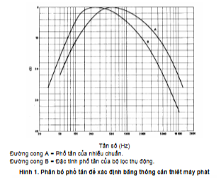
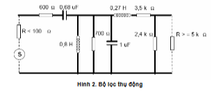
2.1.3.2. Measurement Adapter
The party with the equipment to be measured shall provide a measurement adapter to perform measurements on test samples, especially in the case of digital equipment.
In all cases, the measurement adapter must have:
- An isolated connection to an external power supply;
- Analog audio interface (for digital systems, this interface is a composite interface).
In the case of equipment using integrated antennas, a measurement adapter with a radio frequency frequency combiner combined with a device having an integrated antenna should be used to isolate-combine the integrated antenna with an RF terminal at all operating frequencies of the Equipment Under Test (EUT). The measurement adapter used for radiation measurements.
The technical characteristics of the measurement adapter must include the following basic parameters:
- The circuit connected to the RF combiner must consist of non-linear or passive components:
- The combiner loss of the measurement adapter does not affect the measurement results;
The isolated combiner loss must not depend on the position of the measurement adapter and is not affected by people or objects nearby;
- The isolated combiner loss must be reproducible when the equipment to be measured is moved or replaced;
- The isolated combiner loss does not change when environmental conditions change.
2.1.3.3. Measurement Position and Radiation Layout
The method of determining the measurement position and radiation layout diagram is presented in Appendix A.
2.1.3.4. Transmitter Operating Modes
During testing, the transmitter must be set to an unmodulated mode. The method of obtaining an unmodulated carrier frequency or special modulation types must be agreed upon between the manufacturer and the testing laboratory. This method must be clearly recorded in the test report. This may lead to temporary changes inside the equipment under test. If an unmodulated signal cannot be obtained, peak power must be measured. The manufacturer must specify the measurement method according to Sections 2.2.4 and 2.2.5.
2.1.3.5. Signal Arrangement at the Transmitter Input
The input frequency deviation signal generated from a standard impedance signal generator is applied at the audio input connections unless otherwise specified.
For digital systems, the defined input signal, as specified in Section 2.1.3.1, must be provided from a standard impedance signal generator at the audio input of the measurement adapter.
2.1.4. Analysis of Measurement Results
The analysis of measurement results recorded in the test report is as follows:
a) Compare the measured value with the corresponding limit to determine whether the equipment meets the minimum requirements specified in the standard.
b) The uncertainty of measurement for each parameter measured must be clearly recorded in the test report:
c) The uncertainty of measurement for each measurement must be equal to or less than the values in Table 1.
2.1.5. Measurement Uncertainty
2.1.5.1. Evaluation of Compliance of the Equipment Under Test When Measurement Uncertainty Is Equal to or Less Than the Maximum Acceptable Measurement Uncertainty
The explanation of the measurement results for each measurement and the comparison of the measured value with the corresponding limit described in this standard is as follows:
a) When the measured value does not exceed the limit value, the EUT complies with the requirements of this standard;
b) When the measured value exceeds the limit value, the EUT does not comply with the requirements of this standard;
c) The calculated measurement uncertainty after measurement must be recorded in the test report;
d) The calculated measurement uncertainty can be the largest among the measured values or can be the measurement uncertainty of a specific measurement that has not been calculated. The measurement method and calculation of uncertainty must be recorded in the test report.
2.1.5.2. Evaluation of Compliance of the Equipment Under Test When Measurement Uncertainty Is Greater Than the Maximum Acceptable Measurement Uncertainty
The explanation of the measurement results for each measurement and the comparison of the measured value with the corresponding limit described in this standard is as follows:
a) When the measured value plus the difference between the maximum allowable measurement uncertainty and the calculated measurement uncertainty does not exceed the limit value, the EUT complies with the requirements of this standard,
b) When the measured value plus the difference between the maximum allowable measurement uncertainty and the calculated measurement uncertainty exceeds the limit value, the EUT does not comply with the requirements of this standard;
c) The calculated measurement uncertainty after measurement must be recorded in the test report;
d) The calculated measurement uncertainty can be the largest among the measured values or can be the measurement uncertainty of a specific measurement that has not been calculated. The measurement method and calculation must be recorded in the test report.
2.1.5.3. Maximum Allowable Measurement Uncertainty for Wireless Audio Devices and Wireless Microphones
Table 1 specifies the allowable measurement uncertainty for wireless audio devices and wireless microphones if there are no other instructions in this standard.
Table 1. Maximum Allowable Measurement Uncertainty for Wireless Audio Devices and Wireless Microphones
< ±1 x 10⁻⁷
|
Radio Frequency |
Output Low-Frequency Power |
| < ±0,5 dB | < ±6 dB |
| RF Radiated Power | RF Power When Using a Measurement Adapter |
| < ±0,75 dB | Maximum Frequency Deviation: |
| - From 300 Hz to 6 kHz | |
| - From 6 kHz to 25 kHz | < ±5 % |
| < ±3 dB | Frequency Deviation Limit |
| Transmitter Emission, up to 12,75 GHz | < ±5 % |
| Receiver Emission, up to 12,75 GHz | < ±6 % |
| Transmitter Turn-off Time | < ±6 % |
| Shutdown transmitter settling time | < ±5 % |
The measurement uncertainty values are determined according to the method described in TR 100 028 and must correspond to the expansion factor (coverage factor) k - 1.96 or k - 2 (these coverage factors correspond to confidence levels of 95% and 95.45%, respectively, in cases where the distributions characterizing the actual measurement uncertainties are normal distributions (Gaussian distribution)). The measurement uncertainty values in Table 1 are calculated based on these coverage factors.
The specific coverage factor used to determine the measurement uncertainty must be published.
2.1.5.4. Maximum allowable measurement uncertainty for power equipment of Band II towers
Table 2 specifies the maximum allowable measurement uncertainty applicable to the measurement parameters of low-power Band II equipment.
Table 2. Maximum allowable measurement uncertainty for power equipment of Band II towers
|
Parameter |
Measurement uncertainty |
|
European Radiocommunications Committee |
RF Power When Using a Measurement Adapter |
|
Occupied bandwidth |
< ±6 % |
|
Frequency error |
±100 Hz |
|
Transmitter stop time |
< ±10 % |
|
Spurious emission |
RF Power When Using a Measurement Adapter |
The measurement uncertainty values are determined according to the method described in TR 100 028 and must correspond to the expansion factor (coverage factor) k - 1.96 or k - 2 (these coverage factors correspond to confidence levels of 95% and 95.45%, respectively, in cases where the distributions characterizing the actual measurement uncertainties are normal distributions (Gaussian distribution)). Table 2 is calculated based on these coverage factors.
The specific coverage factor used to determine the measurement uncertainty must be published.
2.2. Measurement methods and limits for transmitters
All measurements must be conducted under normal conditions unless otherwise specified.
2.2.1. Basic requirements for power equipment of Band II towers
Low-power Band II equipment must meet the following requirements:
- Low-power Band II equipment must cease transmission for one minute to eliminate audio modulation.
- Low-power Band II equipment must have an "integrated antenna" (as per Section 1.4.6).
The user interface of low-power Band II equipment must allow selection of any frequency within the band from 88.1 MHz to 107.9 MHz with a minimum step size, and up to 87.6 MHz to 107.9 MHz with a maximum step size as follows:
- Low-power Band II equipment must operate on selected frequencies within the specified band with step sizes of 50 kHz, 100 kHz, or 200 kHz.
- There must be a test mode that allows continuous carrier transmission without audio signal modulation.
2.2.2. Measurement methods and limits for parameters of power equipment of Band II towers
The sections below specify individual testing requirements and measurement limits according to this standard.
Measurements of radiated power and spurious emissions must be carried out in both vertical and horizontal polarization of the measuring antenna.
Low-power Band II equipment must be tested as if it were powered by batteries unless the equipment has a fixed connection to an external power source (see Appendices A and F).
Equipment connected to an external power supply must be tested using this method.
Manufacturers must provide installation instructions for users when connecting transmitters to vehicle power supplies through separate power cables.
2.2.2.1. Measurement position and radiation layout
Testing must be performed at distances ranging from a minimum of 3 meters to a maximum of 10 meters within a reverberation chamber. The measuring antenna must be placed at a height of 1.5 meters, and the EUT antenna must be placed on a rotating table at the same height.
Routine testing is typically conducted at a distance of 10 meters and wherever possible. However, due to the practicality of testing low-power equipment, testing may be conducted at other distances within the reverberation chamber. In such cases, the limits are adjusted according to the following formula:
Limit (xm) = Limit (10 m) + 20 log (10/x)
Where: x is the distance
Since the transmitting antenna size is smaller than 1/10, measurements at a distance of 3 meters will yield better results than at 20³/h, which are considered far-field measurements. See Appendices D, E, and F for additional information.
For testing, all temporary power cables must be installed as per A.2.3.
Appendix F provides an example of how to arrange testing for low-power Band II equipment installed in a truck and powered through a power cable and power converter.
2.2.2.2. Test modulation
The EUT is modulated with a 1 kHz sine wave signal, and the EUT powers each stereo channel input as specified by the manufacturer to achieve a carrier deviation of the transmitter ±75 kHz.
CHỦ THỊCH: FOR integrated (or combined) devices, a stereo or mono 1 kHz sine wave signal (equivalent to stereo amplitude) must be generated to synchronize with the transmitter's input. The amplitude of the signal can be adjusted to precisely set the carrier deviation of the transmitter's output to ±75 kHz.
2.2.2.3. Effective Radiated Power
2.2.2.3.1. Definition
The effective carrier power radiated by the transmitter under specific operating conditions as defined by the manufacturer.
2.2.2.3.2. Limits
The effective radiated power must comply with the limits listed in Table 3.
Table 3. Effective Radiated Power Limits
| Effective Radiated Power Limit | Electric field strength at 10 meters | Electric field strength at 3 meters |
|
50 nW e.r.p (-43 dBm e.r.p) |
42.2 dBuV/m |
52.2 dBuV/m |
2.2.2.3.3. Measurement Method
Place the test equipment (EUT) at the measurement position as per 2.2.2.1.
Apply test modulation to the EUT as per 2.2.2.2.
Adjust the modulation deviation measurement range to have a frequency offset of 275 kHz.
The spectrum analyzer must be set up as follows:
- Resolution bandwidth: 10 kHz;
- Video bandwidth = 30 kHz;
- Frequency span: 500 kHz;
- Detector type: rms;
- Display mode: maximum level.
This conformity test must be conducted at the frequency that produces the highest output power.
Disconnect the audio modulation to the transmitter and measure the carrier power at the test frequency using the receiver/spectrum analyzer.
NOTE: Disconnecting the audio input allows for measuring the carrier power of the frequency modulation (FM) using the receiver/spectrum analyzer.
2.2.2.3.4. Measurement Uncertainty
The maximum measurement uncertainty for the effective radiated power measurement is ±6 dB.
2.2.2.4. Bandwidth Occupancy
2.2.2.4.1. Definition
The occupied bandwidth is the portion of the frequency band within which the transmitter radiates according to the channel specification and out-of-band emission requirements. Typically, the occupied bandwidth is referred to as the frequency mask of the transmitter.
2.2.2.4.2. Limits
The frequency mask of the transmitter must comply with Table 4.
Table 4. Frequency Mask of Transmitter
|
Carrier frequency offset |
Radiated emission power limit (e.r.p) |
Field strength at 10 meters |
Field strength at 3 meters |
|---|---|---|---|
|
-120 kHz |
3 nW (see footnote) |
30 dBµV/m |
40 dBµV/m |
|
-75 kHz |
50 nW |
42.2 dBµV/m |
52.2 dBµV/m |
|
-50 kHz |
50 nW |
42.2 dBµV/m |
52.2 dBµV/m |
|
+50 kHz |
50 nW |
42.2 dBµV/m |
52.2 dBµV/m |
|
+75 kHz |
50 nW |
42.2 dBµV/m |
52.2 dBµV/m |
|
+120 kHz |
3 nW (see footnote) |
30 dBµV/m |
40 dBµV/m |
NOTE: Appendix D presents the limits for spurious emissions. Spurious emissions can be measured similarly to the effective radiated power (e.r.p) using an appropriate substitute method and calibrated dipole antennas under far-field conditions (see Appendix E). However, the measurement must be performed in a fully anechoic chamber without concern for height.
2.2.2.4.3. Measurement Method
Place the equipment under test (EUT) at the measurement position as per 2.2.2.1.
Apply test modulation to the EUT as per 2.2.2.2.
Adjust the modulation deviation measurement range to have a frequency offset of ±75 kHz.
The receiver/spectrum analyzer must be set up as follows:
- Resolution bandwidth: 10 kHz;
- Video bandwidth ≥ 30 kHz;
- Frequency span: 500 kHz;
- Detector type: rms;
- Display mode: maximum level.
This conformity test must be conducted at the frequency that produces the highest output power.
2.2.2.4.4. Measurement Uncertainty
The maximum measurement uncertainty for radiated emissions is 16 dB.
2.2.2.5. Frequency Error
2.2.2.5.1. Definition
The frequency error (Hz) is the difference between the unmodulated carrier frequency and the nominal frequency of the transmitter.
2.2.2.5.2. Limits
The frequency error must not exceed the nominal frequency of the transmitter ±10 kHz.
2.2.2.5.3. Measurement Method
Place the equipment under test (EUT) at the measurement position as per 2.2.2.1.
Apply the test modulation to the EUT as per 2.2.2.2.
Adjust the modulation deviation measurement range to have a frequency offset of 175 kHz.
The receiver/spectrum analyzer must be set up as follows:
- Resolution bandwidth: 10 kHz;
Video bandwidth ≥ 30 kHz;
- Frequency span: 500 kHz;
- Detector type: rms;
- Display mode: normal.
This conformity test must be conducted on the upper, center, and lower channels within the operating frequency band of the EUT.
Disconnect the audio modulation to the transmitter and measure the carrier power at the test frequency using the receiver/spectrum analyzer.
NOTE: Disconnecting the audio input allows for measuring the carrier power of the frequency modulation (FM) using the receiver/spectrum analyzer.
Compare the measured frequency with the nominal frequency.
2.2.2.5.4. Measurement Uncertainty
The maximum measurement uncertainty for the frequency error measurement is ±100 Hz.
2.2.2.6. Transmitter Hold Time
2.2.2.6.1. Definition
The time from when the audio input signal is interrupted until the transmitter stops transmitting or reduces its radiated power to 3 nW e.r.p.
2.2.2.6.2. Limits
The transmitter must stop transmitting within 1 minute to eliminate the audio input signal.
2.2.2.6.3. Measurement Method
Place the equipment under test (EUT) at the measurement position as per 2.2.2.1.
Apply test modulation to the EUT as per 2.2.2.2.
Adjust the modulation deviation measurement range to have a frequency offset of 175 kHz.
The receiver/spectrum analyzer must be set up as follows:
- Resolution bandwidth: 10 kHz;
- Video bandwidth ≥ 30 kHz;
- Frequency span: 500 kHz;
- Detector type: rms;
- Display mode: normal.
This conformity test must be conducted at the frequency that produces the highest output power.
At the test frequency, measure the time interval between disconnecting the audio and turning off the transmitter. Record the off time. The radiated power must not exceed 3 nW e.r.p during the off state.
2.2.2.6.4. Measurement Uncertainty
The maximum measurement uncertainty for the hold time of the transmitter is ±10 seconds.
2.2.2.7. Spurious Emissions
2.2.2.7.1. Definition
Spurious emissions: see Section 1.4.12.
2.2.2.7.2. Limits
2.2.2.7.2.1. Low Power Class II Devices
- The maximum effective radiated power of 3 nW (-55.2 dBm) applies at all frequencies except at the carrier frequency of the transmitter and adjacent modulation sidebands, or
- The maximum field strength is 30 dBuV/m at the measurement point of 10 meters (see Appendices D and E).
2.2.2.7.2.2. Combined Devices
For combined devices, such as low-power Class II devices in mobile phones or other telecommunication devices, the measurement of the effective radiated power of spurious emissions is carried out according to the applicable EN standard for the main device (e.g., EN 301 908-1 for UMTS, EN 301 511 for GSM, etc.).
Spurious emissions of low-power Class II devices are measured under the same test conditions and based on the limits of the main device. The effective radiated power limits are applied when the main device is in idle mode for the low-power Class II device with excluded bands around the desired signal.
2.2.2.7.3. Measurement Method
Place the equipment under test at the measurement position as per 2.2.2.1.
Apply test modulation to the EUT as per 2.2.2.2.
Adjust the modulation deviation measurement range to have a frequency offset of 175 kHz.
The receiver/spectrum analyzer must be set up as follows:
- Resolution bandwidth: 100 kHz;
- Video bandwidth ≥ 100 kHz;
- Detector type: rms;
- Display mode: maximum level.
Spurious emissions must be measured over the frequency range from 30 MHz to 1 GHz, and the measured values must be recorded in the test report.
2.2.2.7.4. Measurement Uncertainty
The maximum measurement uncertainty for the spurious emissions measurement of low-power Class II devices is 10 dB.
The maximum measurement uncertainty for combined devices is as specified in the applicable EN standard for the main device.
2.2.3. Frequency Error
This Section does not apply to low-power Band II equipment.
2.2.3.1. Definition
The frequency error (Hz) is the difference between the unmodulated carrier frequency and the nominal channel frequency. The measurement must be performed under normal test conditions.
2.2.3.2. Limits
The frequency error limits at normal temperature are specified in Table 5.
Table 5. Frequency Error Limits
|
Frequency below 1 GHz |
Frequency above 1 GHz |
|---|---|
|
±60 ppm |
±35 ppm |
2.2.3.3. Measurement Method
The carrier frequency is measured by placing the transmitter in a test fixture (see 2.1.3.2) with a dummy antenna. For devices with external frequency control units, the nominal frequency is measured similarly to the frequency measurement under normal test conditions at each end of the adjustment range (see Section 2.2.5.4).
The measurement must be performed under normal test conditions (see 2.1.2.3)
2.2.4. Network carrier power
This Section does not apply to low-power Band II equipment.
2.2.4.1. Definition
The carrier power of the transmitter is the effective radiated power at the direction of maximum field strength under specified measurement conditions (see Sections 2.1.3.4 and 2.1.3.5), if modulation is not required. Output power is the carrier power published by the manufacturer.
2.2.4.2. Measurement method for devices with integrated antennas
2.2.4.2.1. Measurement method under normal measurement conditions
At measurement positions that meet the requirements specified in Section 2.1.3.3, the device must be placed on a stand at one of the following positions:
- For devices with internal antennas, place the device vertically near the most common usage position with a vertical axis.
- For devices with external grid antennas, place the antenna vertically.
- For devices with external non-grid antennas, the antenna must be placed vertically near the non-conductive stand.
Turn on the transmitter, if possible, set the transmitter to an unmodulated state and adjust the receiver frequency to the frequency of the transmitter being measured. Orient the measurement antenna in the vertical polarization and change the height of the measurement antenna within the specified range until the receiver obtains the highest signal level. Then orient the measurement antenna in the horizontal polarization and change the height of the measurement antenna within the specified range until the receiver obtains the highest signal level.
For transmitters unable to generate unmodulated carrier power, measure peak power using a spectrum analyzer that can display peak power envelope or through special function calculations, using correction factors or any other means.
Rotate the transmitter 360° in the horizontal plane until the receiver obtains the maximum signal level.
NOTE: This value may be lower than the value obtained at heights outside the specified limits.
Replace the transmitter with the substitute antenna described in Section A.1.3 and raise or lower the antenna to obtain the maximum signal level. Adjust the signal level to the substitute antenna until it matches or is relatively close to the signal level received from the transmitter measured by the receiver.
Carrier power equals the power supplied to the substitute antenna, which may be increased if necessary.
Conduct horizontal polarization testing to ensure the highest signal level is obtained.
If a higher value is obtained, it must be recorded in the measurement report.
For transmitters unable to generate unmodulated carrier power, measure peak power using a spectrum analyzer with the following parameters:
Table 6. Parameters for measuring carrier power
Frequency above 1 GHz
|
Frequency below 1 GHz |
Transmitter nominal frequency: (f₀ - 1 MHz to (f₀ + 1) MHz) |
|
|---|---|---|
|
Center Frequency |
(f₀ - 3 MHz to (f₀ + 3) MHz) |
Frequency range |
|
3 MHz |
||
|
Root Mean Square |
2.2. Measurement Methods |
Separation mode |
|
Video Bandwidth |
2.2. Measurement Methods |
Separation mode |
|
Spectrum analyzer display mode |
Vertex |
Vertex |
|
Peak hold |
Carrier power under normal measurement conditions (see Section 2.1.2.3) shall not exceed the limit in Table 7. |
Carrier power under normal measurement conditions (see Section 2.1.2.3) shall not exceed the limit in Table 7. |
2.2.5. Spurious Response
Table 7. Carrier Power
Maximum Radiated Power
|
30 MHz to 47 MHz |
Channel Spacing |
1795 to 1800 MHz |
|---|---|---|
|
20 mW ERP |
None |
87.5 to 108.0 MHz |
|
50 nW ERP |
200 kHz |
The measured equipment's power under normal measurement conditions must fall within ±3 dB of the power level announced by the equipment manufacturer, and this power level must not exceed the value listed in Table 7. The measured power level and the power levels announced by the manufacturer must be recorded in the measurement report. |
2.2.5. Channel Bandwidth
Channel bandwidth (B) is the largest bandwidth that includes the necessary bandwidth of the transmitter. The necessary bandwidth of the transmitter must be measured under the measurement conditions specified in Section 2.2.5.2.
This Section does not apply to low-power Band II equipment.
2.2.5.1. Definitions
With noise sources presented as per Recommendation ITU-R BS 559-2, the frequency deviation of the input audio signal to the EUT must be adjusted according to the manufacturer's stated nominal frequency deviation. If the nominal frequency deviation is not provided by the manufacturer, the standard input level of 500 Hz must be used for multiple input levels. Digital systems must be measured through a test coupler; analog input signal to the test coupler. The low-frequency input level must be increased until the maximum peak deviation is obtained on the frequency deviation meter.
The manufacturer must provide the testing unit with information about the equipment as follows. Block diagram, signal connection structure.
Then increase the input level by 10 dB. Measure the RF output spectrum of the transmitter using a spectrum analyzer with measurement parameters set as in Table 8.
Table 8. Necessary Bandwidth Measurement Parameters
fc: Nominal frequency of the transmitter (Tx)
|
Frequency below 1 GHz |
Transmitter nominal frequency: (f₀ - 1 MHz to (f₀ + 1) MHz) |
|
|---|---|---|
|
Center Frequency |
fc - 1 MHz to fc + 1 MHz |
|
|
3 MHz |
fc - 3 MHz to fc + 3 MHz |
3 kHz |
|
Root Mean Square |
1 kHz |
NOTE 1: If the transmitter is combined with any encoding channels or signaling channels (e.g., tone to the signal path with an acceptable slope). |
|
Video Bandwidth |
1 kHz |
NOTE 1: If the transmitter is combined with any encoding channels or signaling channels (e.g., tone to the signal path with an acceptable slope). |
|
Spectrum analyzer display mode |
Vertex |
Vertex |
|
Peak hold |
Carrier power under normal measurement conditions (see Section 2.1.2.3) shall not exceed the limit in Table 7. |
Carrier power under normal measurement conditions (see Section 2.1.2.3) shall not exceed the limit in Table 7. |
NOTE 2: If the transmitter is combined with more than one audio input, such as stereo systems, then two and the displayed frequency channels are described as above, use f = 16.5 relative to the first input.
NOTE 3: The reference level of the spectrum analyzer will be set to a level not too high. With equipment that cannot achieve in the emission position using high power, the party with the equipment to be tested must have additional methods.
The transmitter output spectrum must be within the mask defined in Figure 3 or Figure 4, where B is the channel bandwidth.
2.2.5.3. Limits
2.2.5.4. Band Edge Limits
The spectrum mask values in the occupied band must be greater than those in Table 9.
Table 9. Band Edge Limits
For equipment below 1 GHz
|
For equipment above 1 GHz |
At the allocated frequency edges, the measured separation limit for average frequency separation is smaller than the two values |
|
|---|---|---|
|
-46 dBc |
-50 dBc |
For frequency-adjustable equipment, the preset channel frequency range must be limited to accommodate the maximum frequency error when measured under normal measurement conditions in Section 2.2.3. |
For equipment with external frequency control, the long-term adjustment must be limited to accommodate the maximum frequency error when measured under normal measurement conditions in Section 2.2.3.
The transmitter operating modes specified in Section 2.1.4.4.
fc: Carrier frequency of the transmitter
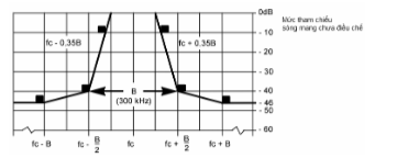
Figure 3. Spectrum mask for analog or digital modulation systems with B = 300 kHz
Figure 3. Frequency mask for analog or digital modulation systems with B = 300 kHz
The measurement method for the transmitter noise is carried out according to 2.2.5.2. The mask value at frequency fc ±300 kHz is -46 dBc, measured using a spectrum analyzer.
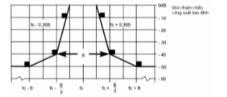
Figure 3. Spectrum mask for analog or digital modulation systems with B = 300 kHz
Figure 4. Mask pattern for the system with B = 600 kHz, 1200 kHz.
The measurement method for the transmitter noise is carried out according to 2.2.5.2. The mask value at frequency fc ±"B" kHz is -50 dBc, measured using a spectrum analyzer.
2.2.6. False emission and casing radiation.
For low-power devices in band II as per Section 2.2.2.7.
Customer assistance service is a service that provides answers to inquiries, advice, guidance on using the service, accepts requests, and provides information to customers about IPTV services on the fixed terrestrial telecommunications network.
False emission: see Section 1.4.12.
2.2.6.2. Measurement method for effective radiated power.
The measurement position must meet the requirements specified in Appendix A, the sample device must be placed on a non-conductive stand at the specified height. The transmitter must operate in the unmodulated carrier state with the assigned carrier power as specified in Section: 2.2.4.
The receiving antenna and receiver will detect the radiation of any false emission components through the specified frequency range, except for the frequency band equal to 2 x B (B is the bandwidth) in the channel where the transmitter is intended to operate.
CHAIRMAN: The excluded frequency bands for measurements are presented in Section 2.2.5.3. The measuring receiver must be adjusted to the frequency range specified in Table 10.
Table 10. Frequency Range.
|
30 MHz to 47 MHz |
Lower frequency. |
Upper frequency. |
|---|---|---|
|
9 kHz to 100 MHz. |
9 kHz. |
120 GHz |
|
100 MHz to 300 MHz. |
9 kHz. |
Two three ten. |
|
300 MHz to 600 MHz. |
30 MHz. |
3 GHz. |
|
600 MHz to 2 GHz. |
30 MHz. |
Two three ten. |
At each frequency where false emission components are detected, the sample device must be rotated to obtain the maximum response, the effective radiated power of that false emission component is determined by an alternative measurement.
If the transmitter has a standby mode, the measurement must be conducted in the standby mode.
2.2.6.3. Limits
The power of false emissions must not exceed the limits given in Table 11.
Table 11. Power Emission Limits.
|
State. |
47 MHz to 74 MHz, 87.5 MHz to 118 MHz, 174 MHz to 230 MHz, 470 MHz to 862 MHz. |
Frequencies below 1000 MHz. |
Frequencies above 1000 MHz. |
|---|---|---|---|
|
Activities |
4 nW. |
250 nW. |
1 µW. |
|
Reserve |
2 nW. |
2 nW. |
20 nW. |
The measuring receiver is usually a voltmeter or a spectrum analyzer using a peak detector. The bandwidth of the measuring receiver is specified in Table 12.
Table 12. Bandwidth of the measuring receiver.
|
Wavelength |
Bandwidth of the measuring receiver. |
|---|---|
|
25 MHz to less than 30 MHz. |
10 kHz |
|
30 MHz to 1000 MHz. |
-54 dBm |
|
Greater than 1000 MHz. |
2.2. Measurement Methods |
2.2.7. Wireless Transmitter On/Off Switching. The receiver does not apply to low-power band II devices or wireless microphones.
2.2.7.1. Definition
The transmitter must have an internal device installed to automatically turn off the RF carrier signal after a period of time without audio input.
2.2.7.2. Measurement Method
The transmitter input must be connected to a power meter with audio input signal. When there is no audio input signal, the timer starts recording the power level. After stopping the timer, the new duration and power level must be recorded.
2.2.7.3. Limitations.
The output power must be reduced to -20 dB within less than 5 minutes after the audio input signal is removed.
2.3. Measurement Methods and Limit Levels for Receivers.
This section does not apply to low-power band II devices.
2.3.1. False Emissions and Radio Radiation.
2.3.1.1. Definition
False emissions from receivers are emissions at any frequencies generated by the receiver's equipment and antennas, amplifiers, converters, or filters.
The levels of false emissions are measured as follows:a) Power level at the external RF port andb) Effective radiated power of the device when radiation from the casing and structure of the device (casing radiation), orc) Effective radiated power of the device when radiation from the casing and integrated antenna, in the case of handheld devices with antennas and no external RF port.
2.3.1.2. Limitations.
The power of false emissions must not exceed the limits listed in Table 13.
Table 13. Limits for Receiver False Emissions.
|
Measurement |
Frequency range from 25 MHz to 1000 MHz. |
Frequency above 1000 MHz. |
|---|---|---|
|
e.r.p. |
2 nW. |
20 nW. |
2.3.1.3. Measurement Method for Casing Power Level at Various Frequency Bands.
This method applies to devices with an external RF port. The external RF port of the receiver under test must be connected to the measuring receiver (see Section 2.2.6.4). The receiver under test must be positioned and adjusted to the frequency ranges specified in Table 14.
Table 14. Frequency Ranges.
|
30 MHz to 47 MHz |
Lower frequency. |
Upper frequency. |
|---|---|---|
|
9 kHz to 100 MHz. |
9 kHz. |
120 GHz |
|
100 kHz to 300 MHz. |
9 kHz. |
Two three ten. |
|
300 MHz to 600 MHz. |
30 MHz. |
3 GHz. |
|
600 MHz to 2 GHz. |
30 MHz. |
Two three five. |
At each frequency where false emissions are detected, the power level recorded is the determined false emission level.
2.3.1.4. Measurement Method for Effective Radiated Power of the Casing.
This method applies to devices with an external RF port.
At a measurement position selected according to Appendix A, the device must be placed on a non-conductive table at a specified height and at the nearest position to the normal usage position provided by the manufacturer.
The test antenna must be oriented vertically polarized and the length of the test antenna must be chosen appropriately for the instantaneous frequency of the receiver (see Section 2.2.6.4). The output of the test antenna must be connected to the measuring receiver. The receiver must be adjusted according to Section 2.3.1.3. At each frequency where false emissions are detected, the height of the test antenna must be adjusted within a specified measurement range until the received signal level is maximized. When using the measurement position according to A.1.1, it is not necessary to change the height of the antenna. Then rotate the receiver 360° in the horizontal plane until the measuring receiver receives the maximum signal level. Record the maximum signal level received by the measuring receiver.
Replace the receiver with a substitute antenna as specified in Section A.1.5. The substitute antenna must be oriented vertically polarized and its length adjusted appropriately for the frequency of the detected false emission component. Connect the substitute antenna to a signal generator that has been calibrated.
Next, the signal generator generates the signal of the detected false emission component. If necessary, adjust the input attenuation of the measuring receiver to increase the sensitivity of the measuring receiver.
Adjust the height of the measuring antenna within the specified height range to ensure the maximum signal is received.
Adjust the input signal level of the replacement antenna so that the signal level indicated by the receiver matches the recorded signal level when measuring the dummy radiator component, adjusted for changes in the receiver's input attenuation.
Record the input signal level of the replacement antenna as power, adjusted for changes in the receiver's input attenuation.
Repeat the measurement with the measuring antenna and the replacement antenna oriented horizontally polarized.
The effective radiated power value of the dummy radiator components is the higher of the two measured power levels when measuring the dummy radiator component at the input of the replacement antenna, adjusted for antenna gain if necessary.
2.3.1.5. Method for Measuring Effective Radiated Power
This method applies to devices with integrated antennas.
The measurement method is similar to 2.3.1.4, except that the receiver's output is connected to an appropriate antenna rather than a dummy antenna.
3. MANAGEMENT PROVISIONS
Wireless audio devices operating in the frequency band from 25 MHz to 2,000 MHz must comply with the corresponding technical requirements of this standard as stipulated in Article 1.1.
4. RESPONSIBILITIES OF ORGANIZATIONS AND INDIVIDUALS
Relevant organizations and individuals are responsible for implementing the regulations on declaring conformity for wireless audio devices operating in the frequency band from 25 MHz to 2,000 MHz and are subject to inspection by state management authorities according to current regulations.
Chapter 5. ORGANIZATION OF IMPLEMENTATION
5.1. The Telecommunications Authority and Provincial Departments of Information and Communications are responsible for organizing guidance and implementing management of wireless audio devices operating in the frequency band from 25 MHz to 2,000 MHz in accordance with this standard.
5.2. In cases where the provisions set forth in this standard are amended, supplemented, or replaced, they shall be implemented according to the new document.
Văn bản gốc (PDF)
Tải văn bản
Bản đồ quan hệ
Bấm vào một văn bản để mở. Viền đỏ = quan hệ làm thay đổi hiệu lực.
Bản dịch
Văn bản này có sẵn ở các ngôn ngữ sau: