
Circular No. 29/2015/TT-BTTTT promulgates the National Technical Regulation on wireless digital image transmission equipment in the frequency band from 1.3 GHz to 50 GHz, applicable to organizations and individuals producing and trading such equipment in Vietnam. The regulation stipulates technical requirements, testing methods, and management of spurious emissions, output power, channel bandwidth, and operating environmental conditions.
适用范围
Organizations and individuals producing and trading wireless digital image transmission equipment in the frequency band from 1.3 GHz to 50 GHz in Vietnam.
要点
- Wireless digital image transmission equipment operating in the frequency band from 1.3 GHz to 50 GHz must comply with the technical provisions of this regulation.
- The output power and channel bandwidth of the transmitter are determined according to the eirp measurement method and calculation formula.
- Spurious emissions on one or more frequencies outside the necessary bandwidth must be controlled within specific power limits.
- Operating environmental conditions such as temperature, humidity, and grid voltage must comply with the specified requirements.
- Testing procedures must be carried out under specific methods and conditions to ensure accurate results.
🌐 本文件的社会影响
- Positive impact: Ensuring the quality of wireless digital image transmission, reducing interference and frequency conflicts.
- Negative impact: Increased costs for businesses due to compliance with complex technical regulations.
❓ 常见问题
How is the output power of the transmitter determined?
The output power (or range of output power) is the average power supplied at the output under defined operating conditions. The eirp measurement method uses either a true average power sensor or an equivalent calibration system.
What are the limits for spurious emissions?
The limit for spurious emissions must not exceed 2 nW in the frequency band from 25 MHz to 1 GHz and 20 nW for frequencies above 1 GHz.
What is the accuracy of the RF (forward) power of the transmitter?
The tolerance for RF (forward) power measurement is ±4 dB, which must be less than or equal to the values listed in Table 8.
Under what environmental conditions must the testing procedures be conducted?
The temperature and relative humidity of the test room must be a combination of temperatures from +15°C to +35°C and relative humidity from 20% to 75%. The grid voltage must be the nominal voltage. The test power supply frequency must be within the range of 49 Hz to 61 Hz.
When does this regulation come into effect?
This circular takes effect from May 1, 2016.
全文
AND COMMUNICATIONS
CIRCULAR
Issuing the "National Technical Regulation on wireless digital video transmission equipment in the frequency range from 1.3 GHz to 50 GHz"
The Minister of Information and Communications issues this Circular to stipulate the National Technical Regulation on wireless digital video transmission equipment in the frequency range from 1.3 GHz to 50 GHz.
______________________
Pursuant to the Law on Standards and Technical Regulations dated June 29, 2006;
Pursuant to the Law on Telecommunications dated November 23, 2009;
WHEREAS, Decree No. 127/2007/NĐ-CP dated August 1, 2007 of the Government detailing and guiding the implementation of certain provisions of the Law on Technical Standards and Regulations;
Based on Decree No. 132/2013/ND-CP dated October 16, 2013 of the Government on the functions, tasks, powers, and organizational structure of the Ministry of Information and Communications;
Pursuant to the proposal of the Director of the Science and Technology Department,
Along with this Circular, the National Technical Regulation on wireless digital video transmission equipment in the frequency range from 1.3 GHz to 50 GHz (QCVN 92:2015/BTTTT) is issued.
Article 1. The Heads of the Office, Directors of Science and Technology Departments, Heads of agencies and units under the Ministry of Information and Communications, Directors of Provincial Departments of Information and Communications, and relevant organizations and individuals shall be responsible for implementing this Circular.
Article 2. This Circular takes effect from May 1, 2016.
Article 3. NATIONAL TECHNICAL REGULATION ON WIRELESS DIGITAL VIDEO TRANSMISSION EQUIPMENT IN THE FREQUENCY RANGE FROM 1.3 GHz TO 50 GHz
|
THE MINISTER Nguyen Bac Son |
QCVN 92:2015/BTTTT
National technical regulation on wireless digital video link equipment in the 1.3 GHz to 50 GHz frequency range
2.1.1. Environmental conditions
2.4.4. Support for Multi PLP
Chapter 1. GENERAL PROVISIONS
1.1. Scope of Application
1.2. Applicability
1.3. Referenced Documents
1.4. Terms and Definitions
dBc
Bandwidth
Chapter 2. TECHNICAL PROVISIONS
2.2. Requirements for ADSL end equipment (ATU-R) - type ADSL2
2.1.2. Dummy antenna
2.1.3. Measurement box
2.1.4. Measurement position and arrangement for radiation measurements
2.1.5. Signal arrangement at the transmitter input
2.2. Measurement conditions
2.2.1. Measurement conditions
2.2.2. Measurement power supply
2.2.3. Normal measurement conditions
2.2.4. Limit measurement conditions
2.3. Technical requirements and measurement methods for transmitters
2.3.1. Output power
2.3.2. Channel bandwidth
2.4. Technical requirements and measurement methods for receivers
2.3.3. Spurious emissions
2.4.1. Spurious emission
2.5. Interpretation of measurement results
ANNEX A (Provisions) Field radiation measurement
3. MANAGEMENT PROVISIONS
4. RESPONSIBILITIES OF ORGANIZATIONS AND INDIVIDUALS
Chapter 5. ORGANIZATION OF IMPLEMENTATION
ANNEX B (Provisions) Overview of measurement methods
QCVN 92:2015/BTTTT is based on ETSI EN 302 064-2 V1.1.1 (2004-04) of the European Telecommunications Standards Institute (ETSI).
QCVN 110:2017/BTTTT was compiled by the Post and Telecommunications Science and Technology Institute, reviewed by the Department of Science and Technology, and promulgated along with Circular No. 24/2017/TT-BTTTT dated October 17, 2017.
Foreword
QCVN 92:2015/BTTTT was compiled by the Post and Telecommunications Engineering Science Institute, reviewed by the Department of Science and Technology, and promulgated by the Ministry of Information and Communications pursuant to Circular No. 29/2015/TT-BTTTT dated October 20, 2015.
NATIONAL TECHNICAL REGULATION ON WIRELESS DIGITAL VIDEO TRANSMISSION EQUIPMENT IN THE FREQUENCY RANGE FROM 1.3 GHz TO 50 GHz National technical regulation on
wireless digital video link equipment in the 1.3 GHz to 50 GHz frequency range
This regulation applies to wireless digital video transmission equipment operating in the frequency range from 1.3 GHz to 50 GHz. This regulation applies to types of equipment with maximum channel bandwidths of 5 MHz, 10 MHz, and 20 MHz.
Chapter 1. GENERAL PROVISIONS
1.1 Scope of Application
The operating frequencies of wireless digital video transmission equipment must comply with national frequency management regulations.
ETSI TR 100 027 (V1.2.1): "Electromagnetic compatibility and Radio spectrum Matters (ERM); Methods of measurement for private mobile radio equipment".
ANSI C63.5: "American National Standard for Calibration of Antennas Used for Radiated Emission Measurements in Electromagnetic Interference (EMI) Control Calibration of Antennas (9 kHz to 40 GHz)".
1.2. Applicability
1.4.1. ADSL line
1.3. Referenced Documents
ETSI TR 102 273 (all parts): "Electromagnetic compatibility and Radio spectrum Matters (ERM); Improvement on Radiated Methods of Measurement (using test site) and evaluation of the corresponding measurement uncertainties".
ETSI TR 100 028 (V1.4.1) (all parts): "Electromagnetic Compatibility and Radio Spectrum Matters (ERM); Uncertainties in the Measurement of Mobile Radio Equipment Characteristics".
CISPR 16-1: "Specification for radio disturbance and immunity measuring apparatus and methods; Part 1: Radio disturbance and immunity measuring apparatus".
IEC 60489-3: "Methods of measurement for radio equipment used in the mobile services. Part 3: Receivers for A3E or F3E emissions".
IEC 60489-1: "Methods of measurement for radio equipment used in the mobile services. Part 1: General definitions and standard conditions of measurement".
Decibel relative to unmodulated carrier power level
NOTE: In cases where a carrier is not required, such as in some digital modulation methods where the carrier cannot be measured, the dBc value is the dB level relative to the average power P.
1.4. Terms and Definitions
dBm
Minimum declared bandwidth, including the necessary transmitter bandwidth
Conducted measurements
Bandwidth The coupling loss between the mobile base station repeater and the donor base station (transmitting base station).
Measurements performed by direct connection to the device under test
Integrated antenna An antenna with or without a connector, designed as part of the device and declared by the manufacturer
Mean power
Average power delivered to the transmission line from a transmitter over a period long enough compared to the lowest modulation frequency present in the modulation envelope under normal operating conditions (integral antenna)
Necessary bandwidth
For each given emission type, the bandwidth must be sufficient to ensure information transmission at the required speed and quality under specified conditions Out-of-band emissions
Emissions on one or more frequencies outside the necessary bandwidth due to the modulation process but excluding spurious emissions
Port (necessary bandwidth)
Any point of connection on or within the device under test used to connect cables to or from the device
Radiation measurements Absolute measurements of the electromagnetic field strength
Mean power (or power range) at the transmitter output under defined operating conditions
Reference bandwidth Bandwidth in which the spurious emission levels have been determined
Spurious emissions
Emissions on one or more frequencies outside the necessary bandwidth whose levels can be reduced without affecting the corresponding information transmission. Spurious emissions include harmonic emissions, parasitic emissions, intermodulation products, and frequency conversion products, but exclude out-of-band emissions (radiated measurements)
Unwanted emissions
ACLR (rated output power)
Including spurious emissions and out-of-band emissions
Wavelength (m) Total symbol period
Field intensity
Spurious emissions Reference field intensity (see Annex A)
Equivalent isotropic radiated power corresponding to P
Distance (see Annex A) Emissions on a frequency or multiple frequencies outside the necessary bandwidth that can be reduced without affecting the transmission of information.
Reference distance (see Annex A)
dBc
|
l |
ac |
|
G |
Declared channel bandwidth |
|
B |
Bandwidth |
|
E |
Orthogonal frequency division multiplexing with coded channels |
|
E° |
eirp |
|
Pc |
Rated output power |
|
P° |
Structure |
|
"5. The pre-tax weighted average cost of capital i (%) is determined according to the formula below:max |
ACLR |
|
"5. The pre-tax weighted average cost of capital i (%) is determined according to the formula below:0 |
Equivalent isotropic radiated powermax |
|
||| R |
FWA |
|
||| R° |
Fixed wireless access |
Bandwidth
|
Outdoor measurement location |
Coupling/Decoupling Net |
d.c |
|
B |
Radio frequency |
SINAD |
|
High Definition Television |
Signal-to-noise-and-distortion ratio |
High Efficiency Mode |
|
SIgnal to Noise And Distortion |
Equivalent Isotropically Radiated Power |
Voltage standing wave ratio |
|
EMC |
ElectroMagnetic Compatibility |
ElectroMagnetic Compatibility |
|
EUT |
Medium Frequency |
Equipment Under Test |
|
FWA |
Fixed wireless access |
Fixed Wireless Access |
|
Open Area Test Site |
Outdoor test position |
OBW |
|
Resolution Bandwidth |
Root Mean Square |
RMS |
|
RF |
Radio frequency |
Radio Frequency |
|
SINAD |
Signal-to-noise-and-distortion ratio |
Signal-to-noise-and-distortion ratio |
|
||| Transmitter |
Generator |
Transmitter |
|
VBW |
Video Bandwidth |
Video Bandwidth |
|
See Article 5 of TR 102 273-2. |
Standing wave voltage ratio |
Voltage Standing Wave Ratio |
Chapter 2. TECHNICAL PROVISIONS
2.2. Requirements for ADSL end equipment (ATU-R) - type ADSL2
2.1.2. Dummy antenna
The technical provisions of this standard apply under the operating environmental conditions of the equipment as published by the manufacturer. The equipment must comply with the technical provisions of this standard when operating under the specified environmental conditions.
2.1.3. Measurement box
Measurement is performed using a dummy antenna, which is essentially a non-reflective, non-radiating load of 50 ohms connected to the antenna connector. - Electronic Information Portal The Standing Wave Ratio (VSWR) at the 50 ohm connection point- Electronic Information Portal must not exceed 1.2:1 for the entire frequency range being measured.
2.1.4. Measurement position and arrangement for radiation measurements
Power radiation measurements are often inaccurate, therefore conducted measurements are preferred (except for false emissions). Equipment used for measurement must be equipped with an appropriate RF power meter interface for conducting power measurements. If this is not possible, a suitable test adapter provided by the manufacturer will be used to convert the radiated signal to a conducted signal. Additionally, radiation measurements must also be performed.
The equipment supplier may provide a test adapter that allows relative measurements to be performed on the sample under consideration.
In all cases, the test adapter must provide:
- An external power supply connection.
For equipment with integrated antennas, the test adapter must include a radio frequency combiner device combined with an integrated antenna device to connect the integrated antenna to the antenna port at the operational frequencies of the EUT. This allows any measurements to be carried out using conducted measurement methods. Only relative measurements are performed and only those at or near the calibrated frequency of the test adapter.
The technical characteristics of the test adapter must be verified by the laboratory and must comply with the following basic parameters:
- The circuitry attached to the RF interface must not contain active devices or nonlinear components;
- The insertion loss of the adapter must not affect the measurement results;
- The insertion loss of the adapter must not depend on the position of the test adapter and must not be affected by surrounding objects or nearby persons;
- The insertion loss of the adapter must be reproducible when the EUT is removed and replaced;
- The insertion loss of the adapter must remain essentially unchanged when environmental conditions change.
2.1.5. Signal arrangement at the transmitter input
See Appendix A.
2.2. Measurement conditions
Within the scope of this standard, the audio/video signal at the transmitter input must be supplied by a signal generator at the calibration impedance connected to known inputs, unless otherwise required. The manufacturer must specify the representative measurement signal.
2.2.1. Measurement conditions
2.2.2. Measurement power supply
Measurements must be carried out under normal test conditions unless limit condition measurements are required.
Test conditions and measurement methods must be defined as in Sections 2.2.2 to 2.2.4.4.
2.2.3. Normal measurement conditions
During compliance testing, the source of the equipment to be tested must be replaced with a test power supply capable of providing normal and limit test voltages as described in 2.2.3.2, 2.2.3.3, 2.2.4.2, 2.2.4.3, and 2.2.4.4. The internal impedance of the test power supply must be sufficiently low to have negligible effect on the measurement result. For testing purposes, the voltage of the test power supply must be measured at the equipment inputs.
For battery-operated equipment, during testing, the battery must be removed from the equipment and replaced with an appropriate test power supply close to the actual battery voltage (the test power supply must have similar technical specifications to the actual battery). When performing radiation measurements, the external power supply wires must be arranged so as not to affect the measurement. If it is necessary to replace the internal battery with an external power supply at the specified voltage, this must be recorded in the test report.
If the equipment is powered through a power cable or power plug, the test voltage must be measured at the point where the power cable connects to the equipment to be tested.
During testing, the power supply voltage must have a tolerance of less than ±1% compared to the voltage at the start of each measurement. This tolerance value is very important for certain measurements. Using a smaller tolerance will yield better measurement uncertainty values. If an internal battery is used, the voltage at the end of each measurement must have a tolerance of less than ±1% compared to the voltage at the start of each measurement.
2.2.4. Limit measurement conditions
Temperature and Humidity
The temperature and humidity of the test room must be a combination of the following values:
- Temperature: +15°C to +35°C;
- Relative Humidity: 20% to 75%.
In case it is not possible to perform testing under these conditions, the actual temperature and relative humidity values of the environment must be clearly recorded in the test result report.
Grid Voltage
The normal test voltage of equipment connected to the grid must be the nominal grid voltage. Within the scope of this Standard, the nominal voltage is the declared grid voltage or any grid voltage designed for the equipment.
The frequency of the AC test power supply must be within the range of 49 Hz to 51 Hz.
Other Sources
When the equipment operates with other types of sources, or different batteries (primary or secondary), the normal test voltage must be declared by the equipment supplier and approved by the laboratories. These values must be recorded in the test result report.
2.3. Technical requirements and measurement methods for transmitters
Limit Temperature
Testing at limit temperatures is specified in Table 1.
Table 1 - Limit Temperature Range
|
General |
-20°C to +55°C |
|
Handheld Equipment |
-10°C to +55°C |
|
Equipment for Normal Indoor Use |
0°C to +55°C |
|
NOTE: The term "equipment for normal indoor use" means that the room temperature is controlled and the indoor minimum temperature is equal to or greater than 5°C. |
|
Procedure for Testing at Limit Temperatures:
Before performing the measurement, the equipment must reach thermal equilibrium in the test room. The equipment must be turned off during the thermal stabilization period. If thermal equilibrium is not checked by measurement, the thermal stabilization period must be maintained for a minimum of one hour.
The sequence of measurements must be selected and the humidity in the test room must be controlled to prevent excessive condensation.
Prior to high-temperature testing, the equipment must be placed in the test room until thermal equilibrium is reached. Then, the equipment must be turned on for one minute in operation mode, after which the equipment must meet the specified requirements.
For tests at sub-limit temperatures, the equipment must be placed in the measurement room until thermal equilibrium is achieved, then switched to standby or reception mode one minute after the equipment meets the specified requirements.
Grid Voltage
The limit measurement voltage for equipment connected to an alternating current power source must be equal to the nominal grid voltage ±10%.
The frequency of the alternating current power network measurement source must be within the range from 49 Hz to 61 Hz.
Rechargeable battery sources
When radio equipment uses rechargeable batteries, the lower limit measurement voltage must be 1.3 times and 0.9 times the nominal battery voltage. For each different type of battery, the lower limit measurement voltage under discharge conditions must be declared by the equipment manufacturer.
Other types of batteries
The lower limit measurement voltage for equipment using primary batteries such as follows:
- For Leclanché or Lithium batteries: the limit measurement voltage is 0.85 times the nominal battery voltage;
- For Mercury batteries: the limit measurement voltage is 0.9 times the nominal battery voltage;
- For other types of primary batteries: the end voltage must be declared by the equipment manufacturer.
In this case, the nominal voltage is considered the upper limit measurement voltage.
Other Sources
For equipment using other sources, or capable of operating with multiple sources, the limit measurement voltages will be agreed upon between the equipment manufacturer and the testing laboratory, these values must be recorded along with the measurement results.
2.3.1. Output power
2.3.2. Channel bandwidth
- Methods using measuring devices: The minimum number of sampled calls required for each of the above indicators is 1,500 calls. Determination can be made using one or both of the following methods, or a combination thereof:
Output power (or power range) is the average power (or power range) that the transmitter supplies at the output under defined operating conditions.
Measurement method for eirp
The output power is detected by a real-time average power sensor device or an equivalent calibration system using appropriate measurement procedures as described in Appendix B.
The transmitter must be modulated with measurement signals as prescribed in 2.1.5.
The EUT must operate at the highest, lowest, and nearest center channels within its operational band.
Measurement method at the antenna port
For guidance, refer to Section 7 in TR 100 027.
Typically, determining the output power is based on measurements or thermal effects of power consumption on the test load or RF voltage across the load. The chosen method will largely depend on the output power, service type, and frequency characteristics.
For example:
a) Thermal measurement method;
b) Temperature-dependent component.
Limit
The manufacturer must publish the output power and equivalent isotropic radiated power (eirp). For equipment usable with different antennas, the manufacturer must publish the maximum antenna gain factor in the user manual.
2.4. Technical requirements and measurement methods for receivers
- Methods using measuring devices: The minimum number of sampled calls required for each of the above indicators is 1,500 calls. Determination can be made using one or both of the following methods, or a combination thereof:
Within the scope of this standard, channel bandwidth (B) is defined as the minimum declared bandwidth, including the necessary transmitter bandwidth (Section 1.1). The necessary transmitter bandwidth is measured with the signal specified in 2.1.5.
Measuring necessary bandwidth
Transmitted power Pmax is measured by a dedicated measuring instrument.
Equivalent isotropic radiated power (eirp) (see NOTE 1), denoted as P0.
NOTE 1: When used with a defined antenna
The spectrum analyzer is set up as follows:
|
- Center frequency: |
PC: nominal transmitter frequency (Tx); |
|
- Frequency span (Span): |
≥ fC - 2B MHz to fC + 2B MHz; |
|
- Resolution bandwidth (RBW): |
3 kHz; |
|
- Video bandwidth (VBW): |
300 Hz; |
|
- Scanning mode: |
Average or rms; |
|
- Display mode: |
Average. |
NOTE 2: If the transmitter combines any signaling or auxiliary coding channels, these channels must be activated before any spectrum measurement.
NOTE 3: In cases of multiple digital modulation types, including COFDM signals, modulation components sinx/x and cross-modulation products caused by nonlinear amplifiers with high crest-to-average ratios. Therefore, an appropriate resolution bandwidth must be selected to minimize measurement errors between true rms envelope levels and envelope levels separated (detected) by the spectrum analyzer. In principle, the maximum resolution bandwidth should not exceed 1/G where G is the total symbol period. A typical value suitable for the DVB-T COFDM system is 3 kHz.
The transmitter output spectrum must be considered in relation to the mask shown in Figure 1, where B is the known channel bandwidth.
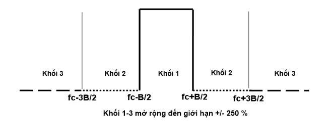
a. Short-sleeved shirt for men 1 - Typical mask for channel bandwidth
Actual power required to determine outside the channel bandwidth B in blocks 2 and 3 as shown in Figure 1.
Block 2 includes adjacent channels in the frequency range from fC - 3B/2 to fC - B/2 and fC + B/2 to fC + 3B/2.
Block 3 lies below fC - 3B/2 and above fC + 3B/2.
A measurement receiver can be used with a suitable filter calibrated for the channel bandwidth. Additionally, the measurement receiver may perform measurements over the frequency range of a pre-defined measurement bandwidth. Total power over the entire bandwidth is the sum of powers of individual bandwidths.
Necessary bandwidth limits
a) Total power limit relative to PMAX
Table 2 - Total power limit relative to PMAX when P0 < 0.3 W eirp
|
|
Each half-band |
Two half-bands |
|
Block 2 |
-36 dB |
-33 dB |
|
Block 3 |
-42 dB |
-39 dB |
Table 3 - Total power limit relative to PMAX when P0 > 0.3 W eirp
|
|
Each half-band |
Two half-bands |
|
Block 2 |
-36 dB - 10 log (P0/0,3) |
-33 dB - 10 log (P0/0,3) |
|
Block 3 |
-42 dB - 10 log (P0/0,3) |
-39 dB - 10 log (P0/0,3) |
b) Discrete spectrum components relative to PMAX
To capture discrete spectrum components that may cause significant asymmetric interference, another limit in these regions is as follows:
Table 4 - Discrete spectrum components relative to PMAX when P0 < 0.3 W eirp
|
|
Power in any 3 kHz bandwidth |
|
Block 2D |
< -48 dB |
|
Block 3D |
< -54 dB |
Table 5 - Discrete spectrum components relative to PMAX when P0 > 0.3 W eirp
|
|
Power in any 3 kHz bandwidth |
|
Block 2D |
< -48 dB - 10 log (P0/0,3) |
|
Block 3D |
< -54 dB - 10 log (P0/0,3) |
2.5. Interpretation of measurement results
- Methods using measuring devices: The minimum number of sampled calls required for each of the above indicators is 1,500 calls. Determination can be made using one or both of the following methods, or a combination thereof:
Radiation on one or more frequencies outside the necessary bandwidth, and the level of this radiation can be reduced without affecting the corresponding information transmission. The false emission level must be determined in one of the following two ways:
a)
i) Power level on a defined load (conducted emission); and
ii) Effective radiated power when radiating from the enclosure and structure of the equipment (enclosure radiation);
send a text message
b) Effective radiated power when radiation from the machine casing and integrated antenna or separate antenna, in cases where the device is compatible with that antenna and does not have a fixed RF connection.
Measuring receiver
The bandwidth of the measuring receiver, if possible, must comply with Section 7 in CISPR 16-1. If a narrower bandwidth is required to achieve the necessary sensitivity, this must be recorded in the measurement report. The maximum bandwidth of the measuring receiver is given in Table 6.
Table 6 - Bandwidth of the measuring receiver
|
Measurement frequency (f) |
Bandwidth of the measuring receiver |
|
f < 1 000 MHz |
100 kHz to 120 kHz |
|
f ≥ 1 000 MHz |
2.2. Measurement Methods |
Method for measuring spurious conducted emissions
This method applies to transmitters with a fixed antenna connector.
a) The transmitter is connected to the measuring receiver through a test load, a 50 ohm impedance attenuator, and if necessary, an appropriate filter is added to prevent overloading the measuring receiver. The bandwidth of the measuring receiver is adjusted so that its sensitivity is at least 6 dB lower than the spurious emission limit specified in Table 7 (see 2.3.3.6). This bandwidth needs to be recorded in the measurement report.- Electronic Information PortalTo measure spurious emissions below the second harmonic of the carrier frequency, a band-reject ("Q" notch) filter centered on the carrier frequency of the transmitter must be used, with a minimum signal attenuation of about 30 dB.
To measure spurious emissions equal to or above the second harmonic of the carrier frequency, a high-pass filter with a cut-off level greater than 40 dB must be used. The cut-off frequency of the filter should be approximately 1.5 times the carrier frequency of the transmitter.
Preventive measures may be required to ensure that test loads do not generate or high-pass filters do not reduce the harmonics of the carrier wave.
b) For carrier frequencies ranging from 1 GHz to 20 GHz, the frequency of the measuring receiver must be adjustable within the range of 25 MHz to 10 times the carrier frequency, but not exceeding 40 GHz. For carrier frequencies above 20 GHz, the measuring receiver must be adjustable within the range of 25 MHz to twice the carrier frequency, except for the channel occupied by the transmitter's carrier frequency and adjacent channels in channel assignment systems. The frequency and level of each spurious emission must be recorded. Emissions in the channel occupied by the transmitter's carrier frequency and adjacent channels in channel assignment systems will not be recorded.
c) If the measuring receiver is not calibrated according to the output power level of the transmitter, the levels of the separated components must be determined by replacing the transmitter with a signal generator and calibrating it to reproduce the frequency and spurious emission level recorded in point c). The absolute power level of each emission must be recorded.
d) The frequency and level of each measured spurious emission and the bandwidth of the measuring receiver need to be recorded in the measurement report.
e) If user power level can be adjusted, repeat steps c) to e) at the lowest possible power level.
f) Repeat steps c) to f) for the transmitter in standby mode, if applicable.
Method for measuring spurious radiated emissions from the machine casing
This method applies to transmitters with a fixed antenna connector. For transmitters without a fixed antenna connector, see 2.3.3.5.
a) The test position is selected according to Appendix A with all requirements for the frequency bands to be measured. The test antenna is initially placed in vertical polarization and connected to the measuring receiver. The bandwidth of the measuring receiver is adjusted so that its sensitivity is at least 6 dB lower than the spurious emission limit in Table 7 (see 2.3.3.6). This bandwidth must be recorded in the measurement report.
The transmitter to be measured is connected to a dummy antenna and fixed on a stand in the standard position (see 2.1.2).
b) For carrier frequencies ranging from 1 to 20 GHz, the frequency of the measuring receiver must be adjustable within the range of 25 MHz to 10 times the carrier frequency, but not exceeding 40 GHz. For carrier frequencies above 20 GHz, the frequency of the measuring receiver must be adjustable within the range of 25 MHz to twice the carrier frequency, excluding the channel where the transmitter operates and adjacent channels in channel assignment systems. The frequency of each separated spurious emission must be recorded. If the measurement is disturbed by interference from external positions, this measurement can be performed in a shielded room and reducing the distance between the test antenna and the transmitter.
c) The measuring receiver is calibrated at each frequency requiring radiation level measurement and the test antenna is raised or lowered within the specified height range until the measuring receiver receives the maximum signal level.
The transmitter must be rotated 360 degrees around the vertical axis to find the maximum received signal level.
d) The test antenna is raised or lowered multiple times within the specified height range until the maximum value is obtained and this maximum value is recorded.° e) A replacement antenna (see A.1.5) replaces the transmitting antenna at the correct position of the transmitting antenna, in vertical polarization. This antenna is connected to a signal generator.
f) At each frequency of spurious emission measurement, the signal generator, replacement antenna, and measuring receiver must be calibrated. The test antenna is raised or lowered within the specified height range until the maximum signal level is obtained on the measuring receiver. The level of the signal generator and the signal level on the measuring receiver as in point e) must be recorded. After calibration due to the gain of the replacement antenna and cable loss between the signal generator and the replacement antenna, this is the spurious emission radiated at this frequency.
g) The frequency and level of each spurious emission measurement and the bandwidth of the measuring receiver need to be recorded in the measurement report.
h) Repeat steps c) to g) with the test antenna in horizontal polarization.
i) If the user power level can be adjusted, repeat steps c) to g) at the lowest possible power level.
j) Repeat steps c) to i) for the transmitter in standby mode, if applicable.
Method for measuring spurious radiated emissions
This method applies to transmitters with an integrated antenna.
a) The test position is selected according to Appendix A with all requirements for the frequency bands to be measured. The test antenna is initially oriented in vertical polarization and connected to the measuring receiver, through an appropriate filter to avoid overloading the measuring receiver if necessary. The bandwidth of the measuring receiver is adjusted so that its sensitivity is at least 6 dB lower than the spurious emission limit specified in Table 7 (see 2.3.3.6). This bandwidth must be recorded in the measurement report.
This method applies to transmitters with integrated antennas.
a) The test position is selected according to Appendix A, meeting all requirements for the frequency bands to be measured. Initially, the test antenna is oriented in the vertical polarization direction and connected to the measuring receiver through an appropriate filter to prevent overload of the measuring receiver if necessary. The bandwidth of the measuring receiver is adjusted so that its sensitivity is at least 6 dB lower than the specified emission limit in Table 7 (see 2.3.3.6). This bandwidth must be recorded in the measurement report.
To measure spurious emissions below the second harmonic level of the carrier frequency, a notch filter ("Q" notch filter) must be used at the center frequency of the transmitter's carrier wave, with a minimum signal attenuation of 30 dB.
To measure spurious emissions at and above the second harmonic level of the carrier frequency, a high-pass filter with a cutoff level greater than 40 dB must be used. The cutoff frequency of the filter must be approximately 1.5 times the carrier frequency of the transmitter.
b) Perform the steps from b) to k) as specified in 2.3.3.4.
Limit
Spurious emission power shall not exceed the values listed in Table 7.
Table 7 - Spurious Emission Radiation
|
State |
Frequency ≤ 1 000 MHz |
Frequency > 1 000 MHz |
|
Activities |
250 nW |
1 m- Electronic Information Portal |
|
Standby |
2 nW |
20 nW |
2.4.1. Spurious emission
2.5. Interpretation of measurement results
These requirements do not apply to receivers used in conjunction with transmitters located at the same transmitting position continuously. The same location is defined as less than 3 meters. In these cases, the receiver must be tested together with the transmitter in operating mode.
- Methods using measuring devices: The minimum number of sampled calls required for each of the above indicators is 1,500 calls. Determination can be made using one or both of the following methods, or a combination thereof:
Spurious radiation from the receiver consists of radiation components at any frequency generated by the receiver equipment and antenna. The level of spurious radiation is measured using one of the following two methods:
a)
i) Power level on a defined load (conducted spurious);
ii) Effective radiated power when radiating from the enclosure and structure of the equipment (enclosure radiation);
send a text message
ii) Effective radiated power when radiating from the case and integrated antenna or separate antenna, in the case where the mobile device is compatible with that antenna and has no fixed RF connector.
Method for measuring conducted spurious components
This method applies to receivers with a fixed antenna connector.
To avoid damaging the receiver, the receiver under test may be connected to a measurement load and a 50 ohm power attenuator combined into a unit with the transmitter. - Electronic Information Portal combined into a unit with the transmitter.
To achieve the required measurement accuracy within the specified limits, the receiver under test must have appropriate dynamic range and sensitivity. The bandwidth of the receiver under test must be adjusted such that its sensitivity is at least 6 dB lower than the spurious emission limit specified in 2.4.1.5. This bandwidth must be recorded in the test report.
a) The receiver inputs must be connected to a 50 ohm receiver under test and the receiver must be in operational state. - Electronic Information Portal and the receiver must be in operational state.
b) For carrier frequencies in the range from 1 GHz to 20 GHz, the receiver under test frequency must be adjusted within the range from 25 MHz to 10 times the carrier frequency, but not exceeding 40 GHz. For carrier frequencies above 20 GHz, the receiver under test must be calibrated within the range from 25 MHz to twice the carrier frequency. The frequency and absolute power level of each spurious emission measured must be recorded in the test report.
c) If the frequency divider is not calibrated according to the input power, then the levels of the divided components must be determined by replacing the receiver with a signal generator and calibrating it to produce the same frequency and spurious emission level as in point b). The absolute power level of each spurious emission component must be recorded.
d) The frequency, level of the measured spurious emission, and bandwidth of the receiver under test must be recorded in the test report.
Method for measuring case radiation
This method applies to receivers with a fixed antenna connector.
a) The test position is selected according to Appendix A with all required frequency band specifications. The initial test antenna must be placed vertically polarized and connected to the receiver under test. The bandwidth of the receiver under test must be adjusted such that its sensitivity is at least 6 dB lower than the spurious emission limit specified in 2.4.1.5. This bandwidth value must be recorded in the test report.
The receiver under test must be fixed on a stand at the standard position and connected to a dummy antenna, see 2.1.2.
b) For carrier frequencies in the range from 1 GHz to 20 GHz, the receiver under test frequency must be adjusted within the range from 25 MHz to 10 times the carrier frequency, but not exceeding 40 GHz. For frequencies above 20 GHz, the receiver under test must be adjusted within the range from 25 MHz to twice the carrier frequency. The frequency of each spurious radiation component must be recorded. If the test position is interfered with by radiation from external positions, this test can be performed in a shielded room and reducing the distance between the test antenna and the transmitter.
c) At each frequency of radiation measurement, the receiver under test must be calibrated and the test antenna raised or lowered within a defined height range until the maximum signal level is detected on the receiver under test.
d) Rotate the receiver 360° degrees around the vertical axis to find the maximum signal level.
e) Raise or lower the test antenna multiple times within a defined height range until the maximum signal level is obtained. Record this signal level.
f) Replace the test antenna (see A.1.5) with a substitute antenna at the same position and in vertical polarization. It must be connected to a signal generator.
g) At each frequency, separate the signal component, calibrate the signal generator, substitute antenna, and receiver under test. Raise or lower the test antenna within a defined height range until the maximum signal level is detected on the receiver under test. The level of the signal generator and the signal level on the receiver under test as in point e) must be recorded. After calibration for the gain of the substitute antenna and cable loss, this level is the spurious radiation component at this frequency.
h) The frequency, level of each measured spurious emission, and bandwidth of the receiver under test must be recorded in the test report.
i) Repeat the measurement steps from b) to h) for the test antenna in horizontal polarization.
Method for measuring radio emission components (spurious radiation)
This method applies to receivers with integrated antennas.
a) The test position is selected according to Appendix A with all required frequency band specifications. The initial test antenna must be placed vertically polarized and connected to the receiver under test. The bandwidth of the receiver under test must be adjusted such that its sensitivity is at least 6 dB lower than the spurious emission limit in 2.4.1.5. This bandwidth must be recorded in the test report.
The receiver under test must be placed and fixed on a stand at the standard position.
b) Perform the steps from b) to i) as specified in 2.4.1.3.
Limit
The power of any spurious emission shall not exceed 2 nW in the frequency range from 25 MHz to 1 GHz and 20 nW for frequencies above 1 GHz.
ANNEX A (Provisions) Field radiation measurement
Interpret the results recorded in the test report for measurements in this Standard as follows:
- The measured values compared to the corresponding limits must be used to determine whether the equipment meets the requirements of this Standard.
- The value of measurement uncertainty for each measured parameter must be recorded in the measurement report;
- The value of measurement uncertainty for each measurement must be equal to or less than the values listed in Table 8.
For measurements following this standard, the measurement uncertainties are calculated according to the method described in Section 5 of Document TR 100 028 and correspond to the expansion factor (coverage factor) k = 1.96 or k = 2 (with confidence levels of 95.45% and 95%, respectively, in cases where the actual distribution of measurement uncertainty follows a normal (Gaussian) distribution).
Table 8 - Measurement Uncertainty
|
Parameter |
Measurement Uncertainty |
|
Radio Frequency |
±1 × 10⁻⁷ |
|
RF Power (directed) |
±4 dB |
|
Transmitter radiation up to 80 GHz |
±8 dB |
|
Receiver radiation up to 80 GHz |
±8 dB |
|
Salinity |
±1°C |
|
Moisture content |
±5 % |
3. MANAGEMENT PROVISIONS
Wireless digital image transmission devices operating in the frequency range from 1.3 GHz to 50 GHz within the scope regulated under Article 1.1 must comply with the technical requirements set forth in this standard.
4. RESPONSIBILITIES OF ORGANIZATIONS AND INDIVIDUALS
Relevant organizations and individuals are responsible for implementing regulations on declaring conformity for wireless digital image transmission devices operating in the frequency range from 1.3 GHz to 50 GHz and are subject to inspection by state management agencies in accordance with current regulations.
Chapter 5. ORGANIZATION OF IMPLEMENTATION
5.1. The Telecommunications Administration and Provincial Departments of Information and Communications are responsible for organizing guidance on managing wireless digital image transmission devices operating in the frequency range from 1.3 GHz to 50 GHz in accordance with this standard.
5.2. In cases where the provisions set forth in this Standard are changed, supplemented, or replaced, they shall be implemented according to the new document.
ANNEX A
Product Name, Goods According to QCVN
Field Radiation Measurement
A.1. Measurement positions and general layout for field radiation measurements using radiation fields
This annex provides three commonly used measurement positions for radiation measurements: non-reflective chamber, non-reflective chamber with ground plane, and outdoor test site (OATS). These measurement positions are often referred to as free-field measurement positions. Both absolute and relative measurements can be performed at these positions. When performing absolute measurements, the chamber must be calibrated. Detailed evaluation procedures are described in Sections 2, 3, and 4 of TR 102 273.
NOTE: To ensure reproducibility and repeatability of radiation measurements, only the measurement positions below should be used for radiation measurements according to this technical standard.
A.1.1. Non-Reflective Chamber
A non-reflective chamber is a closed room typically lined with radio wave absorber materials such as conical foam urethane on the walls, floor, and ceiling. The chamber usually has an antenna support column at one end and a turntable at the other. An example of a non-reflective chamber is shown in Figure A.1.
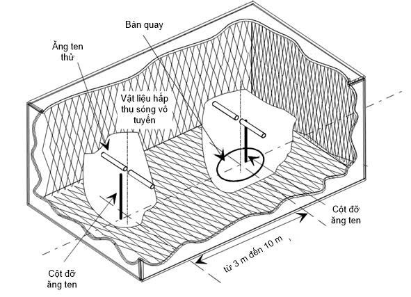
Figure A.1 - Non-Reflective Chamber
The combination of radio wave absorber materials and the chamber enclosure creates a controlled environment suitable for testing purposes. This type of chamber simulates free-space conditions.
The chamber enclosure creates a measurement space that reduces interference levels from surrounding signals as well as other external effects, while the radio wave absorber material minimizes unwanted reflections from walls and ceilings that could affect measurements. In practice, it is easy to enclose to achieve high levels of surrounding interference rejection (from 80 dB to 140 dB), typically resulting in negligible surrounding interference levels.
The turntable rotates 360 degrees in the horizontal plane and is used to place the test sample (EUT) at an appropriate height (for example, 1 meter) above the ground. The chamber must be large enough to allow a minimum measurement distance of 3 meters or 2(d° + d1/λ (m), choosing the larger value (see A.2.5). The measurement distance used in practical measurements must be recorded along with the measurement results.2)2 Non-reflective chambers generally have several advantages over other measurement conditions. They reduce environmental interference, minimize reflections from floors, ceilings, and walls, and are not dependent on weather conditions. However, they also have some disadvantages, such as limited measurement distances and restricted use at low frequencies due to the size of the conical absorber materials. To improve low-frequency performance, a structure combining ferrite tiles and foam urethane absorbers can be used.
All emission, sensitivity, and immunity measurements can be conducted in a non-reflective chamber without any restrictions.
A.1.2. Non-Reflective Chamber with Ground Plane
A non-reflective chamber with a ground plane is a closed room lined with radio wave absorber materials such as conical foam urethane on the interior walls and ceiling. The floor of the chamber is metallic, uncovered, and serves as a ground plane. The chamber usually has an antenna support column at one end and a turntable at the other. An example of a non-reflective chamber with a ground plane is shown in Figure A.2.
This type of chamber simulates an ideal outdoor test site characterized by an infinite perfect ground plane.
- Non-Reflective Chamber with Ground Plane
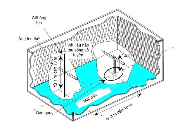
Figure A.2 In this position, the floor forms a desired reflection path, thus the signal received by the receiving antenna is the sum of the direct and reflected signals from the transmitting antenna (or EUT). This results in a unique received signal level for each height of the transmitting antenna (or EUT) and receiving antenna above the floor.
The antenna support column has variable height (from 1 meter to 4 meters) to optimize the position of the test antenna for maximum signal coupling between antennas or between an EUT and the test antenna in the horizontal plane. It is used to place the test sample (EUT) at a specified height, usually 1.5 meters, above the floor. The chamber must be large enough to allow a minimum measurement distance of 3 meters or 2(d
Emission measurements first involve determining the "peak" field strength of the EUT by raising and lowering the receiving antenna on the antenna support column (to obtain the maximum interference of direct and reflected signals from the EUT), then rotating the turntable to find the "peak" (maximum) value in the azimuth plane. At this height of the test antenna, record the amplitude of the received signal. Next, replace the EUT with a substitute antenna (placed at the center phase or amplitude of the EUT), which is connected to a signal generator. Again, find the "peak" value of the signal, and adjust the output level of the signal generator until the received signal level matches that obtained in step 1 on the receiver.
The turntable rotates 360 degrees in the horizontal plane and is used to place the test sample (EUT) at an appropriate height (for example, 1 meter) above the ground. The chamber must be large enough to allow a minimum measurement distance of 3 meters or 2(d° in the horizontal plane, and is used to place the test sample (EUT) at a specified height, usually 1.5 meters above the ground surface. The measurement chamber must be large enough to allow a measurement distance of at least 3 meters or 2(d1/λ (m), choosing the larger value (see A.2.5). The measurement distance used in practical measurements must be recorded along with the measurement results.2)2Non-reflective chambers generally have several advantages over other measurement conditions. They reduce environmental interference, minimize reflections from floors, ceilings, and walls, and are not dependent on weather conditions. However, they also have some disadvantages, such as limited measurement distances and restricted use at low frequencies due to the size of the conical absorber materials. To improve low-frequency performance, a structure combining ferrite tiles and foam urethane absorbers can be used.
The initial emission measurement involves determining the "peak" field strength of the EUT by raising and lowering the receiving antenna on the antenna mast (to obtain the maximum interference from direct and reflected signals from the EUT), then rotating the turntable to find the "peak" value (maximum) in the azimuth plane. At this height of the test antenna, the amplitude of the received signal is recorded. Next, the EUT is replaced with a substitute antenna (placed at the phase center or amplitude center of the EUT), which is connected to a signal generator. The "peak" value of the signal is again found, and the output level of the signal generator is adjusted until the signal level on the receiver matches that obtained in step 1.
Measurements of receiver sensitivity on the ground plane also involve finding the peak value of the field strength by raising or lowering the test antenna on the antenna mast to obtain the maximum combined interference of direct and reflected signals, using a test antenna placed at the phase or amplitude center of the EUT throughout the measurement period. Provide a conversion factor. The test antenna remains at the height as in step 2, while the test antenna is replaced with the EUT. Reduce the signal amplitude to determine the field strength level at which a specified response is obtained from the EUT.
A.1.3. Outdoor test position
Outdoor test site positions include a turntable at one end and an adjustable-height antenna mast on the other end over a ground plane, ideally this ground plane should be highly conductive and extend without limitation. In practice, when good conductivity is achievable, the size of the ground plane may be limited. An example of an open area test site position is shown in Figure A.3.
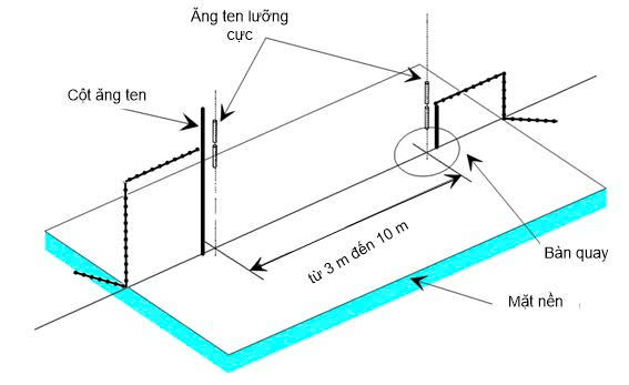
Figure A.3 - Outdoor test site position
The ground plane creates a desired reflection path, thus the signal received by the receiving antenna is the sum of signals from direct and reflected paths. The combination of these two signals results in a unique received signal level corresponding to each height of the transmitting antenna (or EUT) and receiving antenna above the ground plane.
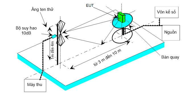
Figure A.4 - Measurement setup at a ground plane test site position
(Setting up OATS for radiated emission testing)
Characteristics of the test site related to antenna positions, turntables, measurement distances, and other arrangements of the test site are similar to those of a ground plane anechoic chamber. In radiation measurements, OATS is also used similarly to a ground plane anechoic chamber.
Typical and common measurement setups for ground plane test sites are presented in Figure A.4.
A.1.4. Test antenna
Test antennas are commonly used in radiation measurement methods. In emission measurements (such as frequency error, effective radiated power, spurious emissions, and adjacent channel power), the test antenna is used to detect the field from the EUT during the first stage of the measurement and from the replacement antenna during other stages. When using a test site to measure receiver characteristics (such as sensitivity and immunity parameters), the test antenna is used as a transmitter.
The test antenna must be mounted on a support that allows it to be used in either horizontal or vertical polarization, and on ground plane test sites (such as in ground plane anechoic chambers and open area test sites), its height can be adjusted within a defined range (typically from 1 m to 4 m).
For frequencies between 30 MHz and 1,000 MHz, it is recommended to use dual-polarized antennas (produced according to ANSI C 63.50 standard). At frequencies of 80 MHz or higher, dual-polarized antennas should have lengths that resonate at the measurement frequency. Below 80 MHz, shorter dual-polarized antennas should be used. However, for spurious emission measurements, a combination of periodic log dual-polarized antennas is used to cover the entire frequency range from 30 to 1,000 MHz._For frequencies above 1,000 MHz, it is recommended to use horn antennas, although periodic log antennas may still be used.
NOTE: The gain of the horn antenna (electromagnetic antenna) is expressed relative to an isotropic radiator.
A.1.5. Replacement antenna
The replacement antenna is used to replace the EUT in transmitter parameter measurements (such as frequency error, effective radiated power, spurious emissions, and adjacent channel power). For measurements in the frequency range from 30 MHz to 1,000 MHz, the replacement antenna must be a dual-polarized antenna (produced according to ANSI C63.50 standard). For frequencies of 80 MHz or higher, dual-polarized antennas must have lengths that resonate at the measurement frequency. Below 80 MHz, shorter dual-polarized antennas should be used. For frequencies above 1,000 MHz, a horn antenna should be used. The center of this antenna must coincide with the phase or amplitude center of the EUT.
A.1.6. Measurement antenna
The measurement antenna is used in receiver parameter measurements of the EUT (such as immunity and sensitivity measurements). Its purpose is to perform electric field strength measurements near the EUT. For measurements in the frequency range from 30 MHz to 1,000 MHz, the measurement antenna should be a dual-polarized antenna (produced according to ANSI C63.5 standard). For frequencies of 80 MHz or higher, dual-polarized antennas must have lengths that resonate at the measurement frequency. Below 80 MHz, shorter dual-polarized antennas should be used. The center of this antenna must coincide with the phase or amplitude center of the EUT as specified in the measurement method.
A.1.7. Stripline coupler
A.1.7.1. Overview
The Stripline coupler is an RF connector device used to connect the integrated antenna of the device to a 50 Ω radio frequency terminal. This allows radiation measurements to be performed without an outdoor test site (open area) but only within a limited frequency range. Both absolute and relative measurements can be made; absolute measurements require calibration of the stripline coupler.
A.1.7.2. Description
The Stripline consists of three conductive plates forming part of a transmission line allowing the device under test to be placed in a known electric field. These conductive plates must be sufficiently rigid to support the devices under test.
Below are two examples of Stripline characteristics
|
|
IEC 60489-3 0 |
FTZ N°512 TB 9 |
|
|
Frequency range used |
dBm/MHz |
1 to 200 |
0.1 increments to 4000 |
|
Size limitations |
Length |
The limestone sample for chemical analysis is collected according to technical sampling regulations in limestone production and usage facilities to ensure that the test sample represents the batch of raw material. |
1200 mm |
|
(including antenna) |
Wide |
The limestone sample for chemical analysis is collected according to technical sampling regulations in limestone production and usage facilities to ensure that the test sample represents the batch of raw material. |
1200 mm |
|
|
Height |
250 mm |
400 mm |
A.1.7.3. Calibration
The purpose of calibration is to establish the relationship between the supply voltage from the signal generator and the field strength at the measurement area designed within the stripline at any frequency.
A.1.7.4. Implementation Method
The stripline connector can be used for all radiation measurements within its calibration frequency range.
The measurement method is similar to that using outdoor measurement positions with the following change: the input jack of the stripline connector is used instead of the test antenna.
A.2. Guidance on Using Radiation Measurement Positions
This section provides specific procedures, equipment setup, and evaluation steps which should be carried out before performing any radiation measurements. This mechanism is common to all measurement positions described in Appendix A.
A.2.1. Evaluating the Measurement Position
No measurement should be conducted on a position that does not have a valid certification. The procedures for certifying different types of measurement positions described in Appendix A (for example, non-reflective chambers, non-reflective chambers with ground planes, and outdoor measurement positions) are detailed in Sections 2, 3, and 4 of TR 102 273.
A.2.2. Preparing the EUT
The manufacturer must provide information about the EUT including operating frequency, polarization, supply voltage, and reference surface. Additional information specific to the type of EUT should include carrier power, channel spacing, other operating modes (such as low and high power modes), and whether operation is continuous or subject to a maximum test cycle (for example, one minute on, four minutes off).
Where necessary, there should be a minimum-sized mounting plate to mount the EUT on a turntable. This plate needs to be made from material with a relatively low dielectric constant (for example, less than 1.5) and low conductivity such as polystyrene, balsa wood...
A.2.3. Powering the EUT
All measurements must be performed using power supplies wherever possible, including measurements with EUTs designed to operate solely on batteries. In all cases, power leads need to be connected to the EUT's power inputs (and monitored by a digital voltmeter) but batteries should remain in the device and insulated from the rest of the equipment, possibly by taping over their contacts.
However, the presence of these power cables may affect the quality of the EUT measurement. For this reason, they need to be made "invisible" for the measurement. This can be achieved by directing them away from the EUT and down below the screen, ground plane, or wall of the measurement position (as appropriate) along the shortest possible paths. Care should be taken to minimize losses on these leads (for example, twisting the leads together, loading them with ferrite beads every 0.15 m or other loads).
A.2.4. Setting Amplitude Control for Analog Voice Measurements
Unless otherwise specified, in all analog voice receiver measurements, the receiver amplitude must be adjusted so that the output power is at least 50% of the rated output power. If the amplitude control is stepped, it should be set so that the first step provides an output power of at least 50% of the rated output power. The receiver amplitude should not be readjusted between normal and limit conditions during measurements.
A.2.5. Distance
The distance for all types of measurement positions should be large enough to allow far-field measurements of the EUT, i.e., it should be equal to or greater than:
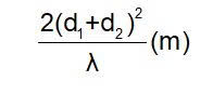
Where:
d1 is the largest diameter of the EUT/dipole after replacement (m);
d2 is the largest diameter of the test antenna (m);
λ is the wavelength of the measurement frequency (m).
Note in the replacement part of this measurement, if both the test antenna and the replacement dipole are half-wave dipoles, the minimum distance for far-field measurement will be: 2λ.
Note in the measurement results report when any of these conditions are not met, additional measurement uncertainty may be combined with the measurement results.
NOTE 1: For fully non-reflective chambers,at any angle of rotation of the turntable, no part of the EUT's amplitude lies outside the "dead zone" of the chamber at the rated measurement frequency.
NOTE 2: "Dead zone" is a volume in a non-reflective chamber (without a floor) where the specified quality has been proven through measurement or guaranteed by the designer/manufacturer. This specified quality is usually the reflection coefficient of the absorber panels or a directly related parameter (such as amplitude and phase uniformity of the signal). However, it should also be noted that the specified levels for the dead zone may vary.
NOTE 3: For non-reflective chambers with a floor,the ability to scan the entire height, i.e., from 1 m to 4 m, should ensure that no part of the test antenna lies below the 1 m height of the absorber panels. With both types of non-reflective chambers, the reflection coefficient of the absorber panels should not be less than -5 dB.
NOTE 4: For non-reflective chambers with a floor and open space measurement positions,no part of the antenna should be within 0.25 m of the floor at any time during the testing process. When any of these conditions are not met, measurements should not be conducted.
A.2.6. Preparing the Position
Cables at both ends of the test position need to be laid horizontally away from the measurement area by a minimum of 2 m (unless they already touch the rear wall in the case of both types of non-reflective chambers), then run vertically and outside the floor or housing (as appropriate) for the measuring equipment. Care should be taken to minimize losses on these leads (for example, by insulating solder joints with ferrite sleeves or other loads). For cables, laying and insulating them should follow the evaluation documentation.
NOTE: For test positions with a reflective floor (such as non-reflective chambers with a floor and open space measurement positions), the above requirement of 2 m distance may not be met.
Adjustment data shall be provided for all items of the measuring equipment. For measurements, the measurement antennas and replacement antennas shall include the relevant gain factor related to the isotropic radiation factor (or antenna factor) at the measurement frequency. The VSWR values of the replacement antennas and measurement antennas should also be known.
Adjustment data for all cables and attenuators shall include external connection loss (insertion loss) and VSWR over the entire frequency range of the measurement. All plots of external connection loss and VSWR must be recorded in the test results for specific measurements.
Where calibration tables/calibration factors are required, they shall be readily available on-site.
For all items of the measuring equipment, the maximum errors and error distribution thereof shall be known, for example:
- Cable loss: ±0.5 dB with rectangular distribution;
- Receiver measurement: signal level accuracy (standard deviation) 1.0 dB with Gaussian error distribution.
At the start of the measurements, system checks shall be performed for the items of measuring equipment used at the test site.
A.3. Signal Combining
A.3.1. Overview
The presence of conductive wires in the radiation field may cause interference in the radiation field and result in additional measurement uncertainty. Such interferences can be reduced by using appropriate combining methods that isolate signals and have minimal impact on the field (e.g., optical and acoustic combining).
A.3.2. Data Signals
Signal isolation can be achieved by using optical, ultrasonic, or infrared methods. The impact on the field can be minimized by suitable optical fiber connections. Suitable infrared or ultrasonic radiating connections are needed to minimize surrounding interference.
A.3.3. Analog and Voice Signals
An acoustic combiner should be used where there is no acoustic output port.
When using an acoustic combiner, it should be checked whether surrounding interference affects the measurement results.
A.3.3.1. Description of Acoustic Combiner
The acoustic combiner consists of a plastic horn, an acoustic tube, and a microphone with a suitable amplifier. Materials used to make the horn and tube should have low electrical conductivity and relative dielectric constant (e.g., less than 1.5 dB).
- The acoustic tube should be long enough to connect from the EUT to the microphone and placed in a position that does not affect the RF field. The acoustic tube needs to have an internal diameter of about 6 mm and thickness of approximately 1.5 mm, and be flexible enough not to obstruct the rotation of the turntable.
- The plastic horn has a diameter corresponding to the speaker size of the EUT, with soft foam rubber attached to its edge, and is mounted on one end of the acoustic tube, while the microphone is mounted on the other end. Aligning the center of the horn with the relevant replica position concerning the EUT is crucial, as this central position significantly influences the frequency response being measured. This can be achieved by placing the EUT in a manufacturer-provided acoustic mating fixture, with the horn being an integral part of it.
- The microphone shall have a flat frequency response within 1 dB in the frequency range from 50 Hz to 20 kHz, with at least a 50 dB linear dynamic range. The sensitivity of the microphone and the output level of the receiver should be suitable to measure a signal-to-noise ratio of at least 40 dB at the nominal output level of the EUT. The size of the microphone must be small enough to fit into the acoustic tube.
- Frequency correction circuits shall adjust the frequency response of the acoustic combiner so that the sound SINAD measurement is accurate (see Appendix F [A.6] of IEC 60489-3).
A.3.3.2. Calibration
The purpose of the audio combiner adjustment is to determine the SINAD sound ratio, which is equivalent to the SINAD ratio at the receiver output.
A.4. Standard Measurement Position
Except for the measurement scheme with bare wire, the standard position is within the measurement locations for equipment not intended to be worn on the person, including handheld devices, which will be placed on a non-conductive table, 1.5 meters high, capable of rotating around a vertical axis. The standard position for such equipment is as follows:
a) For equipment with an integrated antenna, it shall be placed at the nearest position to its normal usage as declared by the manufacturer;
b) For equipment with a fixed external antenna, the antenna shall be positioned vertically;
c) For equipment with a non-fixed external antenna, the device must be placed on a non-conductive stand and the antenna shall be extended vertically.
For wearable equipment, the testing shall be conducted using a mannequin.
The mannequin consists of a rotatable acrylic tube filled with saltwater and placed on the ground.
The tube shall have the following dimensions:
- Height: 1.7 ± 0.1 m;
- Inner diameter: 300 ± 5 mm;
- Wall thickness: 5 ± 0.5 mm
The tube shall be filled with saltwater (NaCl) mixed at a ratio of 1.5 g of salt per liter of distilled water.
The equipment shall be securely attached to the surface of the mannequin at an appropriate height for the device.
NOTE: To reduce the weight of the mannequin, a different tube with a maximum inner diameter of 220 mm may be used.
In the measurement scheme with bare wire, the device under test or the substitute antenna shall be placed within the designated measurement area at the point of normal operation, depending on the field generated, and all shall be mounted on a low dielectric material base (permittivity less than 2).
A.5. Measurement Adapter Box
The measurement adapter box is only used for evaluating equipment that uses an integrated antenna.
A.5.1 Description
The measurement adapter box is a radio frequency frequency combiner device combined with an integrated antenna device to combine this integrated antenna with a 50 Ω radio frequency terminal at the working frequency of the device under test. This allows certain measurements to be performed using direct methods. Relative measurements can only be made at or near frequencies for which the measurement adapter box has been calibrated.
Additionally, the measurement adapter box must provide:
a) A connection to an external power supply;
b) In the case of voice equipment evaluation, an audio interface or direct connection or an audio combiner.
For non-voice equipment, the measurement adapter box may also provide a suitable combiner for data output.
The measurement adapter box is usually provided by the manufacturer.
The operational characteristics of the measurement adapter box must be verified by the laboratory and must comply with the following basic parameters:
a) The insertion loss must not exceed 30 dB;
b) The variation in insertion loss across the measurement frequency band must not exceed 2 dB;
c) The circuit connected to the RF combiner must not contain active components or nonlinear components;
d) The VSWR at the 50 Ω jack must not exceed 1.5 in the measurement frequency band;
e) The insertion loss must not depend on the position of the measurement adapter box and must not be affected by surrounding objects and people. The insertion loss must be reproducible when the device under test is removed and replaced;
f) The insertion loss must remain essentially constant when environmental conditions change.
The characteristics and calibration must be included in the measurement report.
A.5.2 Calibration
The calibration of the measurement adapter box establishes the relationship between the signal generator output and the input field strength to the internal equipment in the measurement adapter box.
Calibration is valid only at a specific frequency and a specific polarization of the reference field.
The actual settings used depend on the type of equipment (for example, data, voice).

Note 1: Combiner equipment, for example AF load/audio combiner (in the case of audio equipment).
Note 2: Equipment for quality assessment, for example RF level meter/distortion factor, bit error rate measuring equipment...
Figure A.5 - Calibration measurement setup
Calibration method:
a) Measure sensitivity in terms of field strength, as described in this standard and record the value of this field strength in dBμV/m and the polarization type used;
b) Place the receiver in the measurement adapter box connected to the signal generator. Record the level generated by the signal generator:
- SINAD is 20 dB;
- Bit error ratio is 0.01; or
- Signal reception ratio is 80%.
The calibration of the measurement adapter box is the relationship between the field strength expressed in dBμV/m and the signal generator level expressed in dBμV emf. This relationship is considered linear.
A.5.3 Implementation Method
The measurement adapter box can be used for measurements in cases where the equipment has an integrated antenna.
It is particularly used in measurements of radiated carrier power and available sensitivity represented as field strength under limiting measurement conditions.
For transmitter measurements, calibration is not necessary as relative measurement methods are used.
For receiver measurements, calibration is necessary as absolute measurements are used.
To apply the desired signal level specified as field strength, it must be converted to the signal generator level (emf) using the calibration curve of the measurement adapter box. Apply this value to the signal generator.
ANNEX B
Product Name, Goods According to QCVN
Overview of measurement methods
This annex provides an overview of high-frequency RF signal measurement methods when using positions and arrangements as described in Annex A. Additionally, this annex also presents a radiation emission measurement method based on loss calculation, instead of direct loss measurement.
B.1 Direct Measurements
Direct measurements are applied to equipment with antenna connectors. For equipment without suitable termination, a combiner or attenuator with accurate termination must be used. Equivalent isotropic radiated power is calculated from the measured value, known antenna gain related to an isotropic antenna, cable losses, and connector losses throughout the entire measurement system, if applicable.
B.2 Radiation Measurements
Radiation measurements are conducted with the assistance of test antennas and measuring receivers as described in Appendix A. Test antennas, measuring receivers, spectrum analyzers, or Volmet selective voltmeters must be calibrated in accordance with the procedures set forth in this Appendix. The equipment to be measured and the test antenna must be oriented so as to achieve maximum radiation power level. This position must be recorded in the measurement results report. The entire frequency range must be measured at this position.
Priority should be given to radiation measurements in non-reflective measurement rooms. At other positions, additional corrections are required (see Appendix A).
a) The measurement position must meet all requirements for the frequency ranges specified for measurement.
b) The transmitter used for testing must be mounted on a stand in the standard position (section A.1.2) and in the transmitting state.
c) The initial test antenna must be oriented in the vertical polarization direction unless otherwise specified. The test antenna must be raised and lowered through the specified height range until the maximum signal level is obtained on the measuring receiver. This will not be necessary if the measurement is performed according to the position as described in A.1.1.
d) Rotate the transmitter 360° degrees around the vertical axis to find the maximum received signal level.
e) Raise and lower the test antenna multiple times, if necessary, to achieve the position with the maximum field strength. Record this maximum value. (This maximum value may be less than the value that can be achieved at heights outside the specified limits).
Policy Bureau, General Political Department Repeat the above measurement for the horizontally polarized antenna.
g) Replace the substitute antenna in the place of the transmitter antenna in the vertical polarization direction. The signal generator frequency must be adjusted to match the carrier frequency of the transmitter.
h)||| Repeat steps from c) to f).
i) Adjust the signal input to the substitute antenna to a level equal to or a known related level separated from the transmitter in the measuring receiver.
j) Repeat the above measurement for the horizontally polarized antenna.
k) Radiated power equals the power supplied by the signal generator and increased after calibrating the gain of the substitute antenna and the loss of the cable between the signal generator and the substitute antenna.
QCVN 110:2017/BTTTT was compiled by the Post and Telecommunications Science and Technology Institute, reviewed by the Department of Science and Technology, and promulgated along with Circular No. 24/2017/TT-BTTTT dated October 17, 2017.
[1] EN 302 064-1 V1.1.2 (2004-07): Electromagnetic compatibility and Radio spectrum Matters (ERM); Wireless Video Links (WVL) operating in the 1,3 GHz to 50 GHz frequency band; Part 1: Technical characteristics and methods of measurement.
[2] EN 302 064-2 V1.1.1 (2004-04): Electromagnetic compatibility and Radio spectrum Matters (ERM); Wireless Video Links (WVL) operating in the 1,3 GHz to 50 GHz frequency band; Part 2: Harmonized EN under article 3.2 of the R&TTE Directive.
原始文件(PDF)
关系图
点击文件即可打开。红色边框=改变效力的关系。
译本
本文件提供以下语言版本: