
These regulations specify requirements for electromagnetic interference resistance and frequency spectrum usage for base station equipment, signal repeaters, and ancillary equipment in wireless mobile communication systems. They include quality assessment criteria for continuous and transient phenomena, as well as post-test operational capability requirements.
Đối tượng áp dụng
These regulations apply to base station equipment (mobile radio transmitters), signal repeaters, and ancillary equipment in wireless mobile communication systems.
Các điểm cốt lõi
- Requirements for electromagnetic interference resistance and frequency spectrum usage
- Quality assessment criteria for continuous and transient phenomena
- Post-test operational capability requirements
- Testing methods for the mentioned equipment.
- Reference standards such as ETSI EN 301 489-50 V1.2.1 (2013-03)
🌐 Tác động xã hội từ văn bản này
- To ensure the quality and performance of wireless mobile communication equipment
- To support effective management of the frequency spectrum
- To provide a basis for technical requirements during equipment approval and certification processes
❓ Câu hỏi thường gặp
What types of equipment does this regulation apply to?
This regulation applies to base stations (mobile radio transmitters), signal repeaters, and ancillary equipment in wireless mobile communication systems.
What does the quality assessment criteria include?
The quality assessment criteria include continuous phenomena (such as stable operation capability) and transient phenomena (such as recovery capability after encountering interference).
How are the testing methods specified?
Testing methods are detailed in Appendix B, including evaluation of BER (Bit Error Rate) and RXQUAL (Radio Signal Quality) for both downlink and uplink paths.
Toàn văn
|
MINISTRY OF INFORMATION AND COMMUNICATION |
SOCIALIST REPUBLIC OF VIET NAM |
|
NUMBER: 31/2016/TT-BTTTT |
Hanoi, on 08 of the Government stipulating the list, management, use of technical equipment and procedures for collecting and using data obtained from such equipment provided by individuals or organizations to detect administrative violations;2 2016 |
CIRCULAR
ISSUING THE NATIONAL TECHNICAL REGULATION ON ELECTROMAGNETIC COMPATIBILITY FOR FIXED RADIO LINKS AND ANCILLARY EQUIPMENT
REGARDING BASE STATIONS, REPEATERS AND AUXILIARY EQUIPMENT IN THE GSM, W-CDMA FDD AND LTE MOBILE COMMUNICATION SYSTEMS
GSM, W-CDMA FDD AND LTE
Pursuant to the Law on Technical Standards and Regulations dated June 29, 2006;June 2024;dated June 6, 2006;
Pursuant to the Law on Telecommunications dated November 23, 2009;
Pursuant to DecreeNo. Decree No. 127/2007/NĐ-CP dated August 1, 2007 of the Government detailing and guiding the implementation of certain provisions of the Law on Technical Standards and Regulations;policiesand guidingFUNCTIONS, DUTIES, POWERS, ORGANIZATIONAL STRUCTURE, OPERATIONAL REGULATIONS, AND RELATIONSHIPS OF MANAGEMENT BOARDS; DUTIES, POWERS OF THE CHAIRPERSON, VICE CHAIRPERSON (IF ANY), SECRETARY, AND MEMBERS OF MANAGEMENT BOARDS195/2013/NĐ-CP dated November 21, 2013 of the Government detailing certain provisions and measures to enforce the Law on Publishingi Pursuant to Decree No. 132/2013/NĐ-CP dated October 16, 2013 of the Government;
Pursuant to Decree No. 132/2013/NĐ-CP dated October 16, 2013 of the Government,"b) In addition to the lists of public services issued according to the provisions of Clause 2, Article 4 of this Decree, specialized agencies under provincial People's Committees shall report to the provincial People's Committee for decision-making on amending, supplementing, or issuing the list of public services funded by the state budget within their jurisdiction and consistent with the local budget capacity within the approved budget by the Provincial People's Assembly, and send it to the Ministry of Finance and relevant ministries and sectors for supervision during implementation.""4. As of March 31, 2021, credit card issuers that issue cards with BINs issued by the State Bank of Vietnam must comply with the Domestic Chip Card Standard."onof the State Treasury;, amended and supplemented by Decree No. 109/2025/NĐ-CP and Decree No. 193/2025/NĐ-CP dated November 21, 2013 of the Prime Minister promulgating the National Radio Frequency Plan;
At the proposal of the Department of Science and Technology, organize credit institutions, foreign bank branches are responsible for organizing the implementation of this Circular.Director of the Science and Technology Department,
The Minister of Information and Communications promulgates this Circular stipulating National Technical Regulations on Electromagnetic Compatibility for base stations, repeaters and auxiliary equipment in the GSM, W-CDMA FDD and LTE mobile communication systems.on electromagnetic compatibility for equipment trAlong with this Circular, National Technical Regulations on Electromagnetic Compatibility for base stations, repeaters and auxiliary equipment in the GSM, W-CDMA FDD and LTE mobile communication systems (QCVN 103:2016/BTTTT) are issued.No.base station, repeater and ancillary trThe Heads of the Office, the Department of Science and Technology, the Heads of agencies and units under the Ministry of Information and Communications, the Directors of Provincial Departments of Information and Communications, and relevant organizations and individuals shall be responsible for implementing this Circular.
Article 1. NATIONAL TECHNICAL REGULATIONS ON ELECTROMAGNETIC COMPATIBILITY FOR BASE STATIONS, REPEATERS AND AUXILIARY EQUIPMENT IN THE GSM, W-CDMA FDD AND LTE MOBILE COMMUNICATION SYSTEMS
Article 2. This Circular takes effect from June 1, 2017.
Article 3. The Head of the Office, the Director of the Science and Technology Department, Heads of agencies and units under the Ministry of Information and Communications, Directors of Provincial Departments of Information and Communications under the Central Government, and related organizations and individuals are responsible for implementing this Circular./.
|
THE MINISTER |
SOCIALIST REPUBLIC OF VIETNAM
QCVN 103:2016/BTTTT
NATIONAL TECHNICAL REGULATION ON ELECTROMAGNETIC COMPATIBILITY FOR BASE STATION, REPEATER AND ANCILLARY EQUIPMENT IN GSM, W-CDMA FDD AND LTE MOBILE INFORMATION SYSTEMS
National technical regulation
Base Provincial People's Committees set specific pricesStationiRepeater,
Ancillary Equipment
of Digital Cellular Telecommunications Systems
HANOI - 2016
TABLE OF CONTENTS
Chapter 1. GENERAL PROVISIONS
1.1. Scope of Application
1.2. Applicability
1.3. Referenced Documents
1.4. Terms and Definitions
1.5. Abbreviations
Chapter 2. TECHNICAL PROVISIONS
2.1. Electromagnetic Compatibility Emission
2.1.1. General Requirements
2.1.2. Specific Conditions
2.2. Immunity
2.2.1. General Requirements
2.2.2. Specific Conditions
3. MANAGEMENT PROVISIONS
4. RESPONSIBILITIES OF ORGANIZATIONS AND INDIVIDUALS
Chapter 5. ORGANIZATION OF IMPLEMENTATION
ANNEX A (Provisions) Measurement Conditions
ANNEX B (Provisions) Evaluation Criteria
ANNEX C (Provisions) Quality Criteria
LIST OF REFERENCES
Foreword
QCVN 103:2016/BTTTT is based on standard ETSI EN 301 489-50 V1.2.1(2013-03) of the European Telecommunications Standards Institute (ETSI).
QCVN 103:2016/BTTTT was drafted by the Telecommunications Administration, reviewed and approved by the Department of Science and Technology, and promulgated by the Ministry of Information and Communications along with Circular No. 31/2016/TT-BTTTT dated December 8, 2016.
AMENDMENT 1:2025 QCVN 07:2023/BXD
ON ELECTROMAGNETIC COMPATIBILITY FOR BASE STATIONS, REPEATERS AND AUXILIARY EQUIPMENT
IN GSM, W-CDMA FDD AND LTE MOBILE INFORMATION SYSTEMS
National technical regulation
Base Provincial People's Committees set specific pricesStationiBase Station, Repeater, Ancillary Equipment
of Digital Cellular Telecommunications Systems GSM, W-CDMA FDD and LTE
1. SCOPE
1.1. Scope of Application
These regulations specify technical requirements for electromagnetic compatibility (EMC) for:
- Base stations in the GSM system;
- Base stations in the IMT-2000 CDMA direct spread W-CDMA FDD (UTRA FDD) mobile communication system;
- Base stations in the LTE (E-UTRA) system;
- Repeaters in the GSM system;
- Repeaters in the IMT-2000 CDMA direct spread W-CDMA FDD (UTRA FDD) mobile communication system;
- Repeaters in the LTE (E-UTRA) system;
and related auxiliary equipment.
These regulations do not specify technical requirements related to antenna ports and emissions from the housing ports of the above radio devices. Such technical requirements are specified in corresponding device technical standards for effective use of radio spectrum.
1.2. Applicability
These technical regulations apply to domestic and foreign agencies, organizations, and individuals engaged in production and business activities involving devices within the scope of these regulations on the territory of Vietnam.
1.3. Referenced Documents
ITU-R Recommendation F.746-3: "Radio-frequency channel arrangements for radio-relay systems".
ETSI TS 125 141 (V9.8.0) (07/2011): "Universal Mobile Telecommunications System (UMTS); Base Station (BS) conformance testing (FDD) (3GPP TS 25.141 version 9.8.0 Release 9)".
ETSI TS 145 008 (V9.7.0) (06/2011): "Digital cellular telecommunications system (Phase 2+); Radio subsystem link control (3GPP TS 45.008 version 9.7.0 Release 9)".
ETSI TS 125 101 (V9.7.0) (05/2011): "Universal Mobile Telecommunications System (UMTS); User Equipment (UE) radio transmission and reception (FDD) (3GPP TS 25.101 version 9.7.0 Release 9)".
ITU-T Recommendation O.153 (10/1992): "Basic parameters for the measurement of error performance at bit rates below the primary rate".
IEC 60721-3-3(1994): "Classification of environmental conditions - Part 3: Classification of groups of environmental parameters and their severities - Section 3: Stationary use at weather protected locations".
IEC 60721-3-4 (1995): "Classification of environmental conditions - Part 3: Classification of groups of environmental parameters and their severities - Section 4: Stationary use at non-weather protected locations".
IEC 60068-2-1 (1990): "Environmental testing - Part 2: Tests. Test A: Cold".
IEC 60068-2-2 (1974): "Environmental testing - Part 2: Tests. Test B: Dry heat".
IEC 60068-2-6 (1995): "Environmental testing - Part 2: Tests - Test Fc: Vibration (sinusoidal)".
ETSI TS 151 010-1 (V9.5.0) (08/2011): "Digital cellular telecommunications system (Phase 2+); Mobile Station (MS) conformance specification; Part 1: Conformance specification (3GPP TS 51.010-1 version 9.5.0 Release 9)".
ETSI TS 125 104 (V9.7.0): "Universal Mobile Telecommunications System (UMTS); Base Station (BS) radio transmission and reception (FDD) (3GPP TS 25.104 version 9.7.0 Release 9)".
ETSI TS 125 106 (V9.2.0): "Universal Mobile Telecommunications System (UMTS); UTRA repeater radio transmission and reception (3GPP TS 25.106 version 9.2.0 Release 9)".
ETSI TS 136 101 (V9.8.0) (06/2011): "LTE; Evolved Universal Terrestrial Radio Access (E-UTRA); User Equipment (UE) radio transmission and reception (3GPP TS 36.101 version 9.8.0 Release 9)".
ETSI TS 136 104 (V9.8.0) (06/2011): "LTE; Evolved Universal Terrestrial Radio Access (E-UTRA); Base station (BS) radio transmission and reception (3GPP TS 36.104 version 9.8.0 Release 9)".
ETSI TS 136 141 (V9.8.0) (07/2011): "LTE; Evolved Universal Terrestrial Radio Access (E-UTRA); Base Station (BS) conformance testing (3GPP TS 36.141 version 9.8.0 Release 9)".
1.4. Terms and Definitions
1.4.1. Abis Interface (Abis Interface)
Physical interface between BTS and BSC.
1.4.2. Bearers (Bearer)
Information transport channels with defined characteristics used for user data or predefined test data transmission.
1.4.3. International Mobile Telecommunications for the year 2000 (IMT-2000)ầfor the year 2000 (IMT-2000) (International Mobile Telecommunications-2000 (IMT-2000))
Third-generation mobile systems, providing access through one or more radio links to various telecommunication services supported by fixed telecommunications networks (e.g., PSTN, ISDN, or IP) and other services dedicated to mobile users.
1.4.4. Necessary Bandwidth (bandwidth necessary)
The frequency band width sufficient to ensure the transmission of information at the required speed and quality under specified conditions.
1.4.5. Radio Communications Equipment (radio communications equipment)
Information equipment comprising one or more transmitters and/or receivers and/or parts thereof used in fixed, mobile, or portable applications.
NOTE: The equipment may operate with auxiliary equipment, but in that case it does not depend on such equipment for its basic function.
1.4.6. Radio Configuration (RC) (radio configuration (RC))
The setting of traffic channel transmission formats for uplink and downlink characterized by physical layer parameters such as transmission speed, modulation characteristics, and spectrum spreading rate.
1.4.7. Radio Digital Unit (radio digital unit)
Equipment performing baseband signal processing and radio unit control functions.
NOTE: See Figures 1 and 2
1.4.8. Radio Equipment (radio equipment)
Equipment including the radio digital unit and the radio unit.
NOTE: See Figures 1 and 2
1.4.9. Radio Unit (radio unit)
Equipment containing the transmitter and receiver.
NOTE: See Figures 1 and 2
1.4.10. RepeatercouncillORS repeater (repeater)
Equipment with two RF ports for connection to antennas, capable of receiving, amplifying, and simultaneously transmitting signals in the BSS transmission band and in the corresponding BSS reception band.
1.4.11. Received Signal Quality (RXQUAL) (RXQUAL)
An indicator determining the received signal level, generated by the base station, used during power handover and control.
NOTE: Characteristics and requirements are specified in Section 8.2 TS 145 008.
Base station equipment
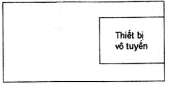
Figure 1: BS with Single-Block Structure
Base station equipment
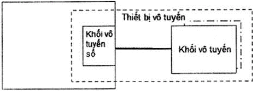
Figure 2: BS with Separated Structure
1.5. Abbreviations
|
ARFCN |
Absolute Radio Frequency Channel Number |
Absolute Radio Frequency Channel Number |
|
AWGN |
Additive White Gaussian Noise |
Additive White Gaussian Noise |
|
BCCH |
Broadcast Control Channel |
Broadcast Control Channel |
|
BER |
Bit Error Ratio |
Bit Error Ratio |
|
BLER |
Block Error Ratio |
Block Error Ratio |
|
BS |
Base Station |
Base Station |
|
BSC |
Base Station Controller |
Base Station Controller |
|
BSS |
Base Station System |
Base Station System |
|
BSSTE |
Base Station System Test Equipment |
Base Station System Test Equipment |
|
BTS |
Base Transceiver Station |
Base Transceiver Station |
|
CDMA |
Code Division Multiple Access |
Code Division Multiple Access |
|
CRC |
Cyclic Redundancy Code |
Cyclic Redundancy Code |
|
DC |
Discontinuous phenomenon applicable to transmitters |
2.1 Electromagnetic Compatibility (EMC) Emission |
|
DCS |
Digital Cellular System |
Digital Cellular System |
|
EDGE |
Enhanced Data rates for GSM Evolution |
Enhanced Data rates for GSM Evolution |
|
EMC |
ElectroMagnetic Compatibility |
ElectroMagnetic Compatibility |
|
EUT |
Equipment requiring measurement and testing |
Equipment Under Test |
|
E-UTRA |
Evolved Universal Terrestrial Radio Access |
Evolved Universal Terrestrial Radio Access |
|
EPC |
Evolved Packet Core |
Evolved Packet Core |
|
FDD |
Frequency Division Duplex |
Frequency Division Duplex |
|
FER |
Frame Error Rate |
Frame Error Rate |
|
FRC |
Fixed Reference Channel |
Fixed Reference Channel |
|
GSM |
Global Mobile Communication System |
Global System for Mobile Communication |
|
Hardware |
Hardware |
Hardware |
|
IF |
Intermediate Frequency |
Intermediate Frequency |
|
IP |
Internet protocol |
Internet Protocol |
|
Integrated Services Digital Network |
Integrated Services Digital Network |
ISDN |
|
Interface between RNC and BS LTE |
Interface between RNC and BS LTE |
lub |
|
Mobile Station |
Mobile Station |
MS |
|
LTE |
Long Term Evolution |
Long Term Evolution |
|
Mobile Station |
Data Traffic Channel |
Data Traffic Channel |
|
Public Switched Telephone Network |
Public Switched Telephone Network |
PSTN |
|
Random Access Channel |
Random Access Channel |
Radio Access Technology |
|
Radio Access Technology |
Radio Network Controller |
Radio Network Controller |
|
RF |
Radio Frequency |
Radio Frequency |
|
Received Signal Quality |
Received Signal Quality |
RNC |
|
Subchannel Power Imbalance Ratio on DownLink |
Subchannel Power Imbalance Ratio on DownLink |
SCPIR_DL |
|
Slow Frequency Hopping |
Slow Frequency Hopping |
SFH |
|
Full rate Speech TCH |
Full rate Speech TCH |
TCH/FS |
|
Transceiver |
Transceiver |
TRX |
|
Universal Terrestrial Radio Access |
Universal Terrestrial Radio Access |
UTRA |
|
UTRA Absolute Radio Frequency Channel Number |
UTRA Absolute Radio Frequency Channel Number |
UTRA Absolute Radio Frequency Channel Number |
|
Universal Terrestrial Radio Access |
Universal Terrestrial Radio Access |
Voice services over AdaptiveMulti- user channels on One Slot |
|
Voice services over AdaptiveMulti- user channels on One Slot |
VAMOS |
Wideband Code Division Multiple Access |
|
Wideband Code Division Multiple Access |
W-CDMA |
Wideband Code Division Multiple Access |
Chapter 2. TECHNICAL PROVISIONS
2.1. Electromagnetic Compatibility Emission
2.1.1. General Requirements
Electromagnetic Compatibility emission requirements at the ports of radio equipment and/or related auxiliary equipment are stipulated in Table 1 of QCVN 18:2014/BTTTT. Measurement conditions are specified in Appendix A of this standard.
2.1.2. Specific Conditions
The specific conditions are specified in Table 1 of this Standard, the measurement methods for emissions are specified in Sections 2.1.2 to 2.1.8 of QCVN 18:2014/BTTTT.
Table 1. Specific conditions for EMC emission measurements
|
Reference section in QCVN 18:2014/BTTTT |
Specific conditions |
||
|
2.1.4. Emissions from DC power supply ports - Limitations |
For this type of equipment, the following limitations apply |
||
|
Frequency range |
Peak, dBµV |
Average, dBµV |
|
|
0.15 MHz to 0.5 MHz |
79 |
66 |
|
|
> 0.5 MHz to 30 MHz |
73 |
60 |
|
2.2. Immunity
2.2.1. General Requirements
The requirements for electromagnetic compatibility immunity at the radio equipment and/or auxiliary equipment ports are specified in Table 4 of QCVN 18:2014/BTTTT. Measurement conditions are specified in Appendix A, evaluation criteria are specified in Appendix B, and quality criteria are specified in Appendix C of this Standard.
2.2.2. Specific Conditions
The specific conditions are specified in Table 2 of this Standard, the test configuration for immunity testing is specified in Section 2.2.2 of QCVN 18:2014/BTTTT.
Table 2 - Specific conditions for EMC immunity test configurations
|
Reference section in QCVN 18:2014/BTTTT |
Specific conditions |
|
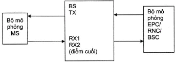
2.2.2 Test configuration (for GSM/EDGE, UTRA, E-TRA base station equipment) |
- Immunity tests on the entire base station must be conducted by establishing connections at the radio interface (e.g., using mobile phone simulators) and the S1/lub/Abis interface (e.g., using EPC/RNC/BSC simulators), and evaluating throughput/BLER/BER (see figure below). - Immunity tests must be performed on both uplink and downlink paths. The tests also include both the radio interface and the S1/lub/Abis interface. Throughput/BLER/BER evaluation can be carried out at either interface, as appropriate, and uplink and downlink measurements may be performed as a single looped path at the radio interface or the S1/lub/Abis interface. In cases where looping is used, care must be taken to ensure that throughput/BLER/BER is not altered due to looping.
|
3. MANAGEMENT PROVISIONS
Radio equipment and auxiliary equipment within the scope of regulation as specified in Section 1.1 must comply with the technical provisions of this Standard.
4. RESPONSIBILITIES OF ORGANIZATIONS AND INDIVIDUALS
Organizations and individuals related have the responsibility to implement certification and conformity declaration regulations for equipment within the scope of this Standard and are subject to inspection by state management agencies according to current regulations.
Chapter 5. ORGANIZATION OF IMPLEMENTATION
5.1. The Telecommunications Administration and Provincial Departments of Information and Communications are responsible for organizing guidance on managing radio equipment according to this Standard.
5.2. In cases where there are changes, additions, or replacements to the provisions of this Standard, they shall be implemented according to the new document.
A.1. Measurement Server
Product Name, Goods According to QCVN
Measurement conditions
For this Standard, the measurement conditions specified in Appendix A of QCVN 18:2014/BTTTT must be applied when appropriate.
This Standard supplements additional provisions regarding measurement conditions for base stations.
A.1 General Requirements
Equipment must be tested under normal measurement conditions consistent with measurement technical requirements, specifically detailed from Section A.1.1 to A.1.5 of Appendix A of this Standard.
Measurement conditions must be recorded in the measurement report.
For emission and immunity test measurements, the remaining measurement conditions are detailed in Sections A.2 to A.5 of Appendix A of this Standard.
For EUT containing more than one BS, all relevant measurements related to each port connection in the EUT must be performed. For BS supporting multiple RATs, antenna port-related measurements must be performed for each supported RAT.
A.1.1 Normal Measurement Environment
When measuring in a normal measurement environment, testing must be conducted within the minimum and maximum limits of the conditions listed in Table A.1.
Table A.1 - Limits for normal measurement environment conditions
|
Conditions |
Minimum |
Maximum |
|
Atmospheric pressure |
86 kPa |
106 kPa |
|
Salinity |
Temperature |
15°C |
|
30°C |
20% |
85% |
|
Relative humidity |
As declared by the manufacturer |
|
|
Vibration |
Negligible |
|
The ranges of atmospheric pressure, temperature, and relative humidity represent the largest possible variations that can occur in an uncontrolled laboratory environment. If these parameters cannot be maintained within the indicated limits, actual values must be recorded in the measurement report.
NOTE: An example of this could be emission radiation measurements in an open measurement area.
A.1.2 Harsh Measurement Environment
The manufacturer must declare one of the following:
1) The type of equipment representing the equipment being tested, defined in IEC 60721-3-3.
2) The type of equipment representing the equipment being tested, defined in IEC 60721-3-4.
3) For equipment not conforming to the above types, information about the suitable environmental conditions of temperature, humidity, and vibration as defined in IEC 60721 must be declared.
NOTE: Performance degradation due to environmental conditions outside standard operating conditions is not measured in this Standard. These environmental conditions may be specified and measured separately.
Harsh Temperature
When measuring in a harsh temperature environment, testing must be conducted at the minimum and maximum standard operating temperatures determined by the manufacturer's declaration for the equipment being tested.
Minimum Temperature
Testing must be performed with the equipment and environmental measurement methods including environmental phenomena affecting the equipment, following the procedures in IEC 60068-2-1.
Maximum TemperatureNo.multi
Testing must be performed with the equipment and environmental measurement methods including environmental phenomena affecting the equipment, following the procedures in IEC 60068-2-2.
NOTE: It is recommended that the equipment should be fully functional before transitioning to lower operating temperatures.
A.1.3 Vibration
When testing under vibration conditions, the test must be conducted when the equipment is vibrated according to a sequence specified by the manufacturer for the measuring equipment. Testing must use equipment and environmental measurement methods including environmental phenomena that affect the equipment, in accordance with the procedures in IEC 60068-2-6. Other environmental conditions must fall within the range specified in Section A.1.1 of Appendix A of this Standard.
NOTE: Higher levels of vibration may cause excessive physical stress inside the equipment after prolonged testing periods. The test group should only vibrate the equipment during RF measurements.
A.1.4. Power Supply Source
When testing under harsh power supply conditions, the test must be performed at the upper and lower limits of the operating voltage as specified by the manufacturer for the tested equipment.
Upper Voltage Limit
The equipment must be supplied with a voltage equal to the upper limit as specified by the equipment manufacturer (when measured at the equipment inputs). Measurements must be carried out at the minimum and maximum stable temperature limits as specified by the manufacturer for the equipment, using the methods described in IEC 60068-2-1: Ab/Ad Testing and IEC 60068-2-2: Bb/Bd Testing: Dry Heat.
Lower Voltage Limit
The equipment must be supplied with a voltage equal to the lower limit as specified by the manufacturer (when measured at the equipment inputs). Measurements must be carried out at the minimum and maximum stable temperature limits as specified by the manufacturer for the equipment, using the methods described in IEC 60068-2-1: Ab/Ad Testing and IEC 60068-2-2: Bb/Bd Testing: Dry Heat.
A.1.5. Definition of Additive White Gaussian Noise (AWGN)
The minimum bandwidth of AWGN noise must be 1.5 times the chip rate in radio access mode (for example, 5.76 MHz for a chip rate of 3.84 Mchip/s). The flatness over this minimum bandwidth must be less than ± 0.5 dB and the crest factor with a probability of 0.001% must exceed 10 dB.
A.2. Signal Arrangement for Testing
Apply Section A.2 of Appendix A of QCVN 18:2014/BTTTT with the following modifications:
The desired RF signal frequency is selected by setting the absolute radio frequency channel number (RF Channel Number) as follows:
- Absolute Radio Frequency Channel Number (EARFCN) for the E-UTRA carrier.
- Absolute Radio Frequency Channel Number (UARFCN) for the UTRA carrier.
- Absolute Radio Frequency Channel Number (ARFCN) for the GSM/EDGE carrier.
A signal path must be established with a suitable testing system capable of evaluating the required criteria (hereinafter referred to as the testing system) at the radio interface and telecommunication port (e.g., S1/lub/Abis interface).
The testing system must be placed outside the testing environment.
When the EUT is required to operate in transmit/receive mode, the following conditions must be met:
- The EUT is controlled to operate at the highest rated transmission power.
- Suitable tests are performed to avoid the influence of unwanted signals on the testing equipment.
- The desired RF input signal is set at a level where operation is not limited by the influence of receiver background noise or strong signals.
+ For E-UTRA, the desired signal can be configured, for example, greater than the standard sensitivity as defined in TS 136 141 15 dB, to provide a stable signal path.
+ For UTRA FDD, the desired signal can be configured, for example, greater than the standard sensitivity as defined in TS 125 141 15 dB, to provide a stable signal path.
+ For GSM/EDGE, the desired receiver input signal level is set at the rated value of -47 dBm.
A.2.1. Multi-layer Base Station Solution
With a multi-layer base station, the base station part with the digital radio unit and the radio unit can be tested separately. The signal path is established in the same manner as in the case of a single-layer base station. The digital radio unit and the radio unit must be connected via an interface capable of establishing a signal path.
A.2.2. Signal Arrangement for Testing at the Transmitter Input
Apply Section A.2.1 of Appendix A of QCVN 18:2014/BTTTT.
A.2.3. Signal Arrangement for Testing at the Transmitter Output
Apply Section A.2.2 of Appendix A of QCVN 18:2014/BTTTT.
A.2.4. BNo. Signal Arrangement for Testing at the Receiver Input
Apply Section A.2.3 of Appendix A of QCVN 18:2014/BTTTT with the following modification:
The desired input signal level is set to provide a stable signal path where operation is not limited by the influence of receiver background noise or strong signals, for example, greater than the standard sensitivity as defined in UTRA TS 125 141 (for FDD) and E-UTRA TS 136 141 is 15 dB.
GSM/EDGE
The desired RF input signal level must have a rated value of -47 dBm.
A.2.5. Signal Arrangement for Testing at the Receiver OutputNo. Apply Section A.2.4 of Appendix A of QCVN 18:2014/BTTTT.
A.2.6. Signal Arrangement for Testing Repeater Equipment
For immunity testing of repeater equipment, the desired RF input signal is fed into an antenna port so that the measured RF output power of each channel is maximized according to the manufacturer's specifications. Repeat the measurement with the desired signal fed into another antenna port, or perform the measurement with a predetermined input signal simultaneously fed to both antenna ports.No. A.3. Excluded Bandwidth
A.3.1. Excluded Bandwidth for Transmitter
There is no excluded bandwidth for transmitter immunity testing for UTRA, E-UTRA, and GSM/EDGE.
A.3.2. Excluded Bandwidth for Receiver
The excluded receiver bandwidth of the BSS is the bandwidth on which receiver immunity testing is not performed.
It extends from 20 MHz below the low end of the receiver band of the base station to 20 MHz above the high end of the receiver band of the base station.
A.4. Narrowband Responses on Receiver
Narrowband responses (spurious responses) occurring on the receiver or transceiver (duplex) during immunity testing at discrete frequencies are determined as follows:
- If during the immunity test, the number of occurrences exceeds the specified tolerance (Appendix C), it is necessary to verify whether the deviation is due to narrowband responses or broadband phenomena (EMC). Therefore, the test must be repeated by increasing the unwanted signal frequency, then decreasing it by a specific foffset amount, specifically:
Narrowband responses (spurious responses) occurring on the receiver or transceiver (dual) during immunity testing at discrete frequencies shall be determined according to the following method:
- If during the immunity test, the number of occurrences exceeds the specified tolerance (Annex C), it is necessary to verify whether the deviation is due to narrowband responses or broadband phenomena (EMC). Therefore, the test must be repeated by increasing the frequency of the unwanted signal, then reducing it by a frequency offset foffset, specifically:
+ For UTRA, f°offset=10MHz
+ For E-UTRA, foffset= 2xBWChannell, where BWCchannell is the channel bandwidth as defined in TS 136 104
+ For GSM/EDGE, f°offset=400 kHz
- If the offset disappears in one or both of the above cases, the narrowband response is considered met;
- If the offset does not disappear, this may be due to the offset causing the unwanted signal frequency to align with the frequency of another narrowband response. In this case, the procedure is repeated with an increase or decrease in the unwanted signal frequency by an amount equal to 1.25 x f°offset;
- If the offset does not disappear when increasing and/or decreasing the frequency, the phenomenon is considered broadband, thus there is an EMC issue and the measuring equipment fails.
The narrowband response is disregarded.
A.5. Normal Measurement Modulation
A signal transmission path is established with an appropriate BSSTE.
Universal Terrestrial Radio Access
Normal measurement modulation must be a carrier channel with data rate characteristics as shown in Table A.2 of this Standard.
If testing is not performed using one of these carrier channels (for example, if the BS does not support any carrier channel), the characteristics of the carrier channel used must be published by the manufacturer and recorded in the test result report.
Table A.2 - Carrier Channel Data Rate
|
Carrier Channel Data Rate |
|
12.2 kbit/s |
|
64 kbit/s |
|
144 kbit/s |
|
384 kbit/s |
GSM/EDGE
Normal measurement modulation is provided by the MS or an appropriate BSSTE.
E-UTRA
Normal measurement modulation must be a carrier channel with data rate characteristics as shown in Table A.3 of this Standard.
If testing is not performed using one of these carrier channels (for example, if the BS does not support any carrier channel), the characteristics of the carrier channel used must be published by the manufacturer and recorded in the test result report.
Table A.3 - Carrier Channel Data Rate
|
E-UTRA Channel Bandwidth [MHz] |
Carrier Channel Data Rate |
|
1,4 |
FRC A1-1 at Section A.1 in TS 136 104 |
|
3 |
FRC A1-2 at Section A.1 in TS 136 104 |
|
5 |
FRC A1-3 at Section A.1 in TS 136 104 |
|
10 |
FRC A1-3 at Section A.1 in TS 136 104 (see Note) |
|
15 |
FRC A1-3 at Section A.1 in TS 136 104 (see Note) |
|
20 |
FRC A1-3 at Section A.1 in TS 136 104 (see Note) |
|
NOTE: This is the data rate of a single carrier channel mapped to 25 resource blocks. Quality criteria must be applicable for each instance of a carrier channel mapped to separate frequency bands with a width of each 25 resource blocks. |
|
ANNEX B
Product Name, Goods According to QCVN
Evaluation Criteria
B.1. General Requirements
Apply the requirements at Section B.1, Appendix B of QCVN 18:2014/BTTTT, with the following modifications:
- Additional information on common RF components or RAT-specific and other HW blocks for connections in multi-RAT supporting BS types must be recorded in the test report.
- Information on the IF amplifier bandwidth immediately before the demodulator as specified in Section B.1, Appendix B of QCVN 18:2014/BTTTT does not apply to radio equipment within the scope of this Standard.
- When a common connection is used by more than one RAT, the evaluation must be conducted on any one RAT.
B.2. Equipment Capable of Providing Continuous Information Connection
Apply the requirements at Section B.2, Appendix B of QCVN 18:2014/BTTTT.
B.2.1. Evaluation of BLER/Throughput/BER at Downlink
The signal level provided to the equipment must be within a range that allows the evaluation of BLER/throughput/BER indices without being affected. Power control must be turned off during the immunity test.
For UTRA (BLER index)
To evaluate the BLER index of the carrier channel used in the immunity test, the transmitter output is connected to a device meeting the requirements for evaluating the BLER index in TS 125 101.
For E-UTRA ((throughput index)
To evaluate the throughput index of the carrier channel used in the immunity test, the transmitter output is connected to a device meeting the requirements for evaluating the throughput index in TS 136 101.
For GSM/EDGE (BER index)
The BER index at the transmitter output is evaluated using one of the techniques described below.
B.2.1.1. Evaluating the BER Index Using Static Layer 1 Functions
The transmitter under test must be operated under the following test conditions:
The BSS must be configured with the maximum number of TRXs, with ARFCNs distributed across the entire bandwidth announced by the manufacturer for the tested BSS equipment. One TRX must be configured to support the BCCH channel. If the manufacturer announces that the equipment supports slow frequency hopping, this function must be activated.
Each TRX must transmit a GSM signal in normal modulation mode, and the BSSTE must be connected to the antenna port. A defined bit sequence with a length not exceeding one superframe (1326 TDMA frames) is fed into the channel encoder in the BSS and obtained as a bit sequence at the output after channel decoding in the BSSTE.
All logical channels supported by the BSS must be tested. The test must be repeated for each TRX in the BSS configuration, for each logical BSS channel supported.
NOTE: Some logical channels are only supported by configuring TRXs to support BCCH.
For measurements in VAMOS mode, the test is performed on both VAMOS sub-channels with the absolute value of SCPIR-DL (dB) being the smallest.
The bit sequence from the transmitter output is monitored by the test system under the following test scenarios, and the BER index of type 2 bits for the TCH/FS channel is evaluated. The BER value must not exceed the value specified in Section C.1 of this Standard.
Test Scenarios:
Article GMSK Modulation
1) For BER measurements, if the BSS supports SFH, the BSS must hop across the largest possible range and number of ARFCNs supported by the configuration. If SFH is not supported, the test must be performed on the initial, middle, and final frequency channels of the operating band. In both cases, the tests must be repeated until all radio devices in the BSS configuration have been tested on all carrier frequencies.
If the test is conducted with TCH/FS, a TCH/FS signal in normal modulation mode from the BSSTE is fed into the receiver input of the BSS. The unprotected type 2 bits obtained from the BSS receiver after channel decoding but before de-interleaving must be compared to the unprotected type 2 bits provided by the BSSTE.
If the test is not conducted with TCH/FS, a normal modulation mode PDTCH test signal from the BSSTE is applied to the receiver input of the BSS. The data bits decoded from the BSS receiver must be compared to the original bits from the BSSTE.
NOTE: The decoded data bits represent the encoded bits in a block, taken from the receiver without any improvement through signal processing from encoding/decoding.
The testing must be carried out at the following levels of test signal power:
a) Lower limit (20 dB higher than the standard sensitivity of the tested BSS), specifically defined in Table B.1 of this Standard, under static propagation conditions.
b) -40 dBm, under static propagation conditions.
c) -15 dBm for GSM 900, -18 dBm for E-GSM 900 for multi-carrier BTS with multi-carrier receivers, and -23 dBm for DCS1800, applicable under static propagation conditions.
d) pico-BTS: -5 dBm for GSM 900 and -14 dBm for DCS 1800, applicable under static propagation conditions.
e) Lower limit (20 dB higher than the standard sensitivity of the tested BSS), specifically defined in Table B.1 of this Standard, under EQ50 propagation conditions (measured by the balanced method with a speed of 50 km/h), this step does not apply to pico-BTS.
f) -40 dBm, under EQ50 propagation conditions (measured by the balanced method with a speed of 50 km/h), this step does not apply to pico-BTS.
2) For the RACH channel, the test must be performed on the initial, final, and middle frequency channels of the operating band of the BS. A measurement signal including RACH bursts from the BSSTE is fed into the receiver input of the BSS. The ratio of RACH bursts at the receiver input that are not accurately identified by the BSS must be measured.
The testing must be carried out at the following levels of measurement signal power:
a) lower limit (20 dB higher than the standard sensitivity of the tested BSS), specifically defined in Table B.1 of this Standard, under static propagation conditions.
b) -40 dBm, under static propagation conditions.
c) -15 dBm for GSM 900, -16 dBm for E-GSM 900 BTS for multi-carrier BTS with multi-carrier receivers, and -23 dBm for DCS 1800 under static propagation conditions.
3) The FER value on TCH/FS is measured at hopping frequencies under noise conditions, two signals are connected to the receiver input of the BSS via a combiner network. The desired signal with RF level specified in Table B.1 hops cyclically over four carrier frequencies under static conditions. The noise signal must be a continuous random signal, modulated GMSK on a single carrier with a signal level 10 dB higher than the desired signal.
Testing must be conducted with hopping frequencies centered around the middle frequency channel.
Article 8-PSK, QPSK, 16-QAM and 32-QAM modulation
If the Base Station Subsystem (BSS) supports slow frequency hopping, the BSS must hop across the largest possible range and number of Absolute Radio Frequency Channel Numbers (ARFCNs) within the configuration supported by the BSS. If slow frequency hopping is not supported, testing must be performed on the first, middle, and last frequency channels of the operating band. In both cases, the tests must be repeated until all radio equipment in the BSS configuration has been tested on all carrier frequencies.
A test PDTCH signal under normal modulation conditions is fed into the receiver input of the BSS from the BS Test Equipment (BSTE). The decoded data bits obtained from the receiver block of the BSS are compared with the original bits from the BSTE.
NOTE: The decoded data bits represent the encoded bits in a block, taken from the receiver without any improvement through signal processing from encoding/decoding.
Testing must be conducted at the following test signal power levels:
a) The lower limit level specifically defined in Table B.1, under static propagation conditions.
b) -40 dBm, under static propagation conditions.
c) The maximum limits specified in Table B.1, under static propagation conditions.
d) Steps a and b must be repeated with the input signal frequency of 8-PSK and if QPSK is supported, the modulated signal must be randomly offset by ±0.1 ppm per burst. For each burst, the sign of the frequency offset is chosen based on a 511-bit pseudo-random sequence, as defined in ITU-T Recommendation O.153.
Table B.1 - Permitted Input RF Levels for Static Class 1 Receiver Functionality Testing
|
Type of BTS |
Lower Limit GMSK, 8-PSK and QPSK |
Limit THE electronic media in Vietnam 8-PSK and QPSK |
Lower Limit 16-QAM and 32-QAM EGPRS2-A |
Lower Limit 16-QAM and 32-QAM EGPRS2-B |
Upper Limit 16-QAM and 32-QAM |
|
GSM 900/DCS 1800 BTS |
-84 dBm |
-26 dBm |
-84 |
-78 |
-28 |
|
GSM 900 micro-BTS M1 |
-77 dBm |
-24 dBm |
-77 |
-71 |
-27 |
|
GSM 900 micro-BTS M2 |
-72 dBm |
-19 dBm |
-72 |
-66 |
-22 |
|
GSM 900 micro-BTS M3 |
-67 dBm |
-14 dBm |
-67 |
-61 |
-17 |
|
GSM 900 pico-BTS P1 |
-68 dBm |
-16 dBm |
-68 |
-62 |
-19 |
|
DCS 1800 micro-BTS M1 |
-82 dBm |
-24 dBm |
-82 |
-76 |
-27 |
|
DCS 1800 micro-BTS M2 |
-77 dBm |
-19 dBm |
-77 |
-71 |
-22 |
|
DCS 1800 micro-BTS M3 |
-72 dBm |
-14 dBm |
-72 |
-66 |
-17 |
|
DCS 1800 pico-BTS P1 |
-75 dBm |
-17 dBm |
-75 |
-69 |
-20 |
If the Equipment Under Test (EUT) does not support TCH/FS, the manufacturer must publish the logical channel for evaluation purposes and the corresponding quality criteria.
B.2.1.2. Evaluating the BER Index Using RXQUAL
The output of the transmitter is connected to a device that meets the requirements of TS 151010-1 for evaluating RXQUAL. RXQUAL must be monitored during the test. The RXQUAL value must not exceed the value specified in Section C.1 of this Standard.
NOTE: This device may be a suitable GSM MS for monitoring RXQUAL.
B.2.2. Evaluating the BLER/Throughput/BER Index at the Uplink
For UTRA (BLER index)
The BLER value at the receiver output reported by the BS is monitored at the lub interface using an appropriate measuring instrument.
For E-UTRA (throughput index)
The throughput value at the receiver output reported by the BS is monitored at the S1 interface using an appropriate measuring instrument.
For GSM/EDGE (BER index)
The BER index at the receiver output can be evaluated using the techniques described below.
B.2.2.1. Evaluating BER Using RXQUAL
The RXQUAL value reported by the BTS or BSS is monitored using an appropriate measuring instrument.
B.2.2.2. Evaluating theNo. BER Using BER Report
The BER index of type 2 bits at the receiver output is evaluated using an appropriate measuring instrument.
If the EUT does not support TCH/FS, the manufacturer must publish the logical channel for evaluation purposes and the corresponding evaluation criteria.
NOTE: This can be done through a "loopback test" where the BTS transmitter is used to send decoded data from the receiver back to the measuring instruments, which generated the bit stream. For immunity testing at the signal ports, a "loopback test" includes an external connection between the signal ports.
B.2.3. Evaluating the RF Gain Variation of the Loopback Device
The parameter used to evaluate the loopback device's performance is the RF gain within the operating band.
B.3. Equipment Unable to Provide Continuous Information Connection
Apply the requirements set forth in Section B.3, Appendix B of QCVN 18:2014/BTTTT.
B.4. Auxiliary Equipment
Apply the requirements set forth in Section B.4, Appendix B of QCVN 18:2014/BTTTT.
B.5. Equipment Classification
Apply the requirements set forth in Section B.5, Appendix B of QCVN 18:2014/BTTTT.
APPENDIX C
Product Name, Goods According to QCVN
Quality Criteria
C.1. Quality Criteria for Continuous Phenomena Applicable to Base Station Equipment and Loopback Devices
C1.1. Base Station Equipment (BS)
For UTRA
The BLER value must be calculated based on the CRC estimate for each transport block.
During uplink and downlink immunity testing of the BS, the BLER value must be less than 1x10^-3 and the BS must operate as intended. If uplink and downlink are estimated using loopback, the value must be less than 2x10^-3.-2 After testing, the BS must operate as intended, without losing user control functions or stored data, and the data link must be maintained.-2.
If possible, testing should be conducted using bearer channels with data rate and throughput characteristics as defined in Table C.1 of this Standard. If testing is not conducted using one of these bearer channels (for example, the BS does not support this type of bearer channel), the characteristics of the used bearer channel must be recorded in the measurement report.
For E-UTRA
Throughput in Table C.1 of this Standard is calculated relative to the maximum throughput of FRC. The maximum throughput for an FRC equals the size of the load
number of subframes on the uplink per second. x The uplink and downlink of the BS must meet the quality criteria specified in Table C.1 of this Standard during testing. If the uplink and downlink are evaluated using loopback method, then the criteria are determined by twice the throughput reduction specified in Table C.1 of this Standard. After each test, the BS must operate as intended, without losing user control functions, stored data, and the data link must be maintained.
Table C.1 - Quality Criteria for Continuous Phenomena for BS
E-UTRA Channel Bandwidth [MHz]
|
Data Rate of Bearer Channel |
TNo.Quality Criteria |
(see Notes 1 and 2)of the Government stipulating functions, tasks, powers, and organizational structure of the Ministry of Home Affairsquantity |
|
1,4 |
Throughput > 95% |
No Service Loss |
|
3 |
FRC A1-3 at A.1 in TS 136 104 |
No Service Loss |
|
5 |
FRC A1-3 at A1 in TS 136 104 |
No Service Loss |
|
10 |
FRC A1-3 at A1 in TS 136 104 |
No Service Loss |
|
15 |
(See Note 3) |
No Service Loss |
|
20 |
(See Note 3) |
No Service Loss |
|
NOTE 1: Quality criteria, throughput >95% / No service interruption, also apply if a different bearer channel with other characteristics is used in the test. NOTE 2: Quality criteria, throughput >90%/No service disruption, applicable to cases where the uplink and downlink paths are looped. NOTE 3: This is the data rate for a case where the carrier channel maps to 25 resource blocks. The quality criteria must be met for each continuous application of a carrier channel using separate frequency bands with a width of each 25 resource blocks. |
||
If possible, testing should be conducted using bearer channels with data rate and throughput characteristics as defined in Table C.1 of this Standard. If testing is not conducted using one of these bearer channels (for example, the BS does not support this type of bearer channel), the characteristics of the used bearer channel must be recorded in the measurement report.
For GSM/EDGE
Downlink
During testing, the value of the Bit Error Rate (BER) for the downlink must be evaluated according to one of the test methods specified in Section B.2.1, Appendix B of this Standard.
In the case of applying the test method at Section B.2.1.1, Appendix B of this Standard, the measured BER value for type 2 bits of TCH/FS during testing shall not exceed 1.6%.
NOTE 1: This BER value is the upper limit defined in TS 145 008 when RXQUAL = 3.
In the case of applying the test method at Section B.2.1.2, Appendix B of this Standard, during testing, the RXQUAL value shall not exceed 3.
After testing, the EUT must operate as intended without losing user control functions or stored data, and the data link must be maintained.
Uplink
During testing, the value of the Bit Error Rate (BER) for the uplink must be evaluated according to one of the test methods specified in Section B.2.2, Appendix B of this Standard.
In the case of applying the test method at Section B.2.2.1, Appendix B of this Standard, during testing, the RXQUAL value shall not exceed 3.
In the case of applying the test method at Section B.2.2.2, Appendix B of this Standard, during testing, the measured BER value for type 2 bits of TCH/FS shall not exceed 1.6%.
NOTE 2: This BER value is the upper limit defined in TS 145 008 when RXQUAL = 3.
For base stations, the uplink RXQUAL value shall not be tested more than three times.
If possible, testing should be conducted using bearer channels with data rate and throughput characteristics as defined in Table C.1 of this Standard. If testing is not conducted using one of these bearer channels (for example, the BS does not support this type of bearer channel), the characteristics of the used bearer channel must be recorded in the measurement report.
C1.2. Repeater Equipment
The RF gain of the EUT is measured throughout the exposure testing process. During the execution of the test, this value shall not deviate more than ±1 dB from the value before the test is conducted.
After testing, the EUT must operate as intended without losing user control functions or stored data.
C.2. Criteria for evaluating burst phenomena for base station equipment and repeater equipment
C2.1. Base Station Equipment
At the end of each exposure testing process, the EUT must operate with a negligible number of disconnected users.
After completing all tests including a series of individual exposure tests, the EUT must operate as intended without losing user control functions or stored data as published by the manufacturer, and the data link must be maintained.
C2.2. Repeater Equipment
The RF gain of the EUT must be measured before testing and after each exposure testing process. At the end of each exposure testing process, this value shall not change more than ±1 dB. After completing all tests including a series of individual exposure tests, the EUT must operate as intended without losing user control functions or stored data as published by the manufacturer, and the RF gain of the EUT shall not change more than ±1 dB.
C.3. Quality criteria for independently tested auxiliary equipment
Apply the requirements at Section C.4, Appendix C of QCVN 18:2014/BTTTT. Additionally, apply Sections C.3.1 and C.3.2, Appendix C of this Standard.
C3.1. Quality criteria for continuous phenomena for auxiliary equipment
The EUT must continue to operate as intended during and after testing. When the device is used as intended, there shall be no degradation in quality or loss of function below the permissible level published by the manufacturer. Quality may decrease within allowable limits. If the minimum quality level or allowable quality reduction is not published by the manufacturer, this level can be determined based on product descriptions, product documentation, and reasonable expectations from users regarding the device if used as intended.
C3.2. Quality criteria for burst phenomena for auxiliary equipment
The EUT must continue to operate as intended after testing. When the device is used as intended, there shall be no degradation in quality or loss of function below the permissible level published by the manufacturer. Quality may decrease within allowable limits. If the minimum quality level or allowable quality reduction is not published by the manufacturer, this level can be determined based on product descriptions, product documentation, and reasonable expectations from users regarding the device if used as intended.
LIST OF REFERENCES
[1] ETSI EN 301 489-50 V1.2.1 (2013-03) Electromagnetic Compatibility and Radio Spectrum Matters (ERM); ElectroMagnetic Compatibility (EMC) Standard for radio equipment and services; Part 50: Specific Conditions for Cellular Communication Base Station (BS), Repeater and Ancillary Equipment.
Văn bản gốc (PDF)
Tải văn bản
Bản đồ quan hệ
Bấm vào một văn bản để mở. Viền đỏ = quan hệ làm thay đổi hiệu lực.
Bản dịch
Văn bản này có sẵn ở các ngôn ngữ sau: