
These regulations specify technical requirements for ADSL terminal equipment types ADSL2 and ADSL2+, including technical characteristics, measurement methods, and quality management. The main contents of these regulations include: scope of application, terms and symbols, technical requirements for transmission signals, electrical characteristics, bandwidth response, total transmit power, DC resistance, longitudinal balance, crosstalk attenuation and crosstalk distortion within the telephone band and ADSL, upstream or downstream transmission rates. These regulations also stipulate the responsibilities of organizations and individuals related to certification and declaration of conformity for these devices.
Đối tượng áp dụng
ADSL terminal equipment types ADSL2 and ADSL2+
Các điểm cốt lõi
- Technical requirements for transmission signals, electrical characteristics
- Measurement methods for bandwidth response, total transmit power, DC resistance, longitudinal balance
- Quality management and the responsibilities of organizations and individuals related to certification and declaration of conformity for these devices.
- References from ITU-T Recommendation G.992.3 (04/2009) and G.992.5 (01/2009).
- Provisions on management and implementation organization of the Telecommunications Administration and Provincial Departments of Information and Communications.
🌐 Tác động xã hội từ văn bản này
- Ensuring technical quality for ADSL2 and ADSL2+ equipment
- Supporting certification and declaration of conformity
- Helping to manage these devices effectively in the telecommunications system
❓ Câu hỏi thường gặp
To which types of equipment does this regulation apply?
Applies to ADSL terminal equipment types ADSL2 and ADSL2+
What are the main technical requirements of this regulation?
Including transmission signals, electrical characteristics, bandwidth response, total transmit power, DC resistance, longitudinal balance
Who is responsible for certifying and declaring conformity for these devices?
Organizations and individuals related
Toàn văn
|
MINISTRY OF INFORMATION AND COMMUNICATIONS AND COMMUNICATIONS |
SOCIALIST REPUBLIC OF VIET NAM |
|
Number: 36/2015/TT-BTTTT |
Hanoi, day23 December 2015 |
CIRCULAR
Issuing the "National Technical Regulation on ADSL2 and ADSL2+ Devices"
Pursuant to the Law on Standards and Technical Regulations dated June 29, 2006;
Pursuant to the Law on Telecommunications dated November 23, 2009;
WHEREAS, Decree No. 127/2007/NĐ-CP dated August 1, 2007 of the Government detailing and guiding the implementation of certain provisions of the Law on Technical Standards and Regulations;
Based on Decree No. 132/2013/ND-CP dated October 16, 2013 of the Government on the functions, tasks, powers, and organizational structure of the Ministry of Information and Communications;
Pursuant to the proposal of the Director of the Science and Technology Department,
The Minister of Information and Communications issues this Circular to stipulate the National Technical Regulations on ADSL2 and ADSL2+ devices.policiesEquipment
Article 1. This Circular includes the National Technical Regulation on ADSL2 and ADSL2+ devices (QCVN 98:2015/BTTTT).
Article 2. This Circular takes effect from July 1, 2016.
Article 3. The Director of the Office, Heads of Departments of Science and Technology, Heads of agencies and units under the Ministry of Information and Communications, Directors of Provincial Information and Communications Departments, and relevant organizations and individuals shall be responsible for implementing this Circular./.
|
THE MINISTER
|
QCVN 98:2015/BTTTT
NATIONAL TECHNICAL REGULATION ON ADSL2 AND ADSL2+ END EQUIPMENT
National technical regulation on ADSL2 and ADSL2+ transceiverl 2.1. General requirements
2.4.4. Support for Multi PLP
Chapter 1. GENERAL PROVISIONS
1.1. Scope of Application
1.2. Applicability
1.3. Referenced Documents
1.4. Terms and Definitions
1.5. Abbreviations
Chapter 2. TECHNICAL PROVISIONS
2.2. Requirements for ADSL end equipment (ATU-R) - type ADSL2
2.3. Requirements for ADSL end equipment (ATU-R) - type ADSL2+
TESTING METHODS
3. Bandwidth capacity
3.1. Total transmission power
3.2. 3.3. DC resistance
3.4. Impedance
3.5. Crosstalk balance
3.6. NEXT attenuation and NEXT distortion
3.7. Upstream transmission rate (or downstream transmission rate)
3.8. PSD mask
Preface
5. RESPONSIBILITIES OF ORGANIZATIONS AND INDIVIDUALS
5. RESPONSIBILITIES OF ORGANIZATIONS AND INDIVIDUALS
6. IMPLEMENTATION ORGANIZATION
QCVN 110:2017/BTTTT was compiled by the Post and Telecommunications Science and Technology Institute, reviewed by the Department of Science and Technology, and promulgated along with Circular No. 24/2017/TT-BTTTT dated October 17, 2017.
QCVN 98:2015/BTTTT is based on TCVN 8077:2009 "ADSL2 and ADSL2+ transceiver equipment on subscriber lines - Technical requirements".shallTechnical regulations and testing methods comply with Recommendations G.992.3 (04-2009) and G.992.5 (01-2009) of the International Telecommunication Union (ITU) and ETSI TS 101 388 V1.4.1 of the European Telecommunications Standards Institute (ETSI).
QCVN 98:2015/BTTTT was compiled by the Post and Telecommunications Science and Technology Institute, reviewed by the Department of Science and Technology, and issued together with Circular No. 36/2015/TT-BTTTT dated December 23, 2015.
TECHNICAL REGULATION ON END EQUIPMENT
NATIONAL TECHNICAL REGULATION ON ADSL2 AND ADSL2+ END EQUIPMENT
NATIONAL TECHNICAL REGULATION ONNational technical regulation on ADSL2 and ADSL2+ transceiverThis standard specifies technical requirements for ADSL end equipment types ADSL2 and ADSL2+ supporting simultaneous voice and data services over a POTS line on a single pair of metallic wires, bonded, frequency-division duplex (FDD).Ề This standard applies to organizations and individuals, both domestic and foreign, engaged in production and business activities involving equipment within the scope of this standard on the territory of Vietnam.ẾQCVN 22:2010/BTTTT: "National technical regulation on electrical safety for telecommunications terminal equipment".TCVN 7189: 2009: Information technology equipment - Radio frequency interference characteristics - Limits and measurement methods.ITU-T G992.1: 1999 Asymmetric digital subscriber line (ADSL).
ITU-T G996.1: 2001 Test procedures for digital subscriber line (DSL) transceivers.lITU-T O.42: 1988 Equipment to measure nonlinear distortion using the four-tone intermodulation method.
Chapter 1. GENERAL PROVISIONS
1.1. Scope of Application
1.4. Definitions
1.2. Applicability
1.4.1. ADSL line
1.3. Referenced Documents
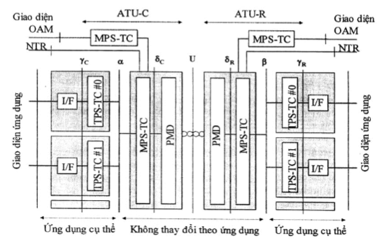
An ADSL line is characterized by a metallic transmission line using analog coding algorithms. These algorithms allow monitoring of digital and analog signal transmission throughout the line. An ADSL line is bounded by two endpoints called line terminations. Line terminations are points where analog coding ends and digital signals are monitored to ensure integrity. The ADSL line is defined between reference points a and b (see Figure 1).
1.4.2. Upstream
Data transmission direction from ATU-R to ATU-C (see Figure 1).
1.4.3. Downstream
Data transmission direction from ATU-C to ATU-R (see Figure 1).
1.4.4. Tip and Ring organize credit institutions, foreign bank branches are responsible for organizing the implementation of this Circular.Tip and Ring are two parts of a telephone plug. Tip is the keyed part and Ring is the cylindrical part.
1.4.5. Actual transmission rate
The total data rate transmitted across all channels in one direction.
1.4.6. Transmission state
The state of ATU-C or ATU-R achieved after all initialization and test processes are completed. In this state, data is transmitted over the channels.
Figure 1 - Functional model of ATU
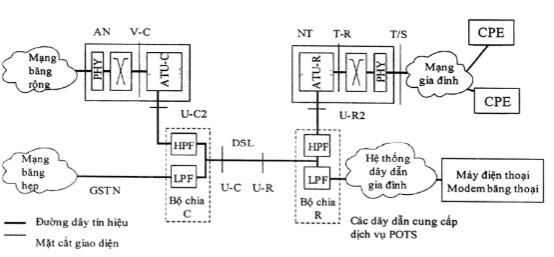
Figure 2 - Reference model for the case of using a splitter at the far end
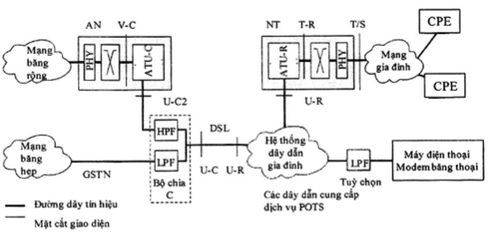
Figure 3 - Reference model for the case without a far-end splitterANNEX I.A[31]energy
ADSL
Asymmetric digital subscriber line
Asymmetric digital subscriber line
ATU
ADSL transceiver
ADSL Transceiver Unit
ATU-C
ATU at the central office (i.e., the operator's side)No.ATU at the Central office end in ATU-R
|
1.5. Abbreviations |
||
|
ATU at the remote terminal (i.e., the customer's side) |
ATU at the remote terminal end |
ATU-x |
|
ATU-C or ATU-R |
ATU-C or ATU-R |
Central office |
|
Customer premises |
Customer premises equipment |
Customer premises equipment |
|
DSL |
Digital subscriber line |
Digital subscriber line |
|
Frequency division duplex |
GSTN |
General switched telephone network |
|
Add distilled water to make up to 1 liter of solution. |
Arbitration |
General switched telephone network |
|
dated October 20, 2015 of |
HPF |
High-pass filter |
|
High-Pass filter |
LCL |
Longitudinal conversion loss |
|
Longitudinal coversion loss |
LPF |
Low-pass filter |
|
FDD |
Secondary Common Control Physical Channel |
Low pass filter |
|
MAXNOMPSDus |
Maximum nominal PSD level of ATU-R |
Max NOMPSDus |
|
MAXNOMATPus |
Maximum nominal aggregate transmit power of ATU-R |
Maximum nominal aggregate transmit power |
|
MBW |
Measured bandwidth |
Measure Band Width |
|
MIB |
Management information base |
Management information base |
|
NOMPSDus |
Nominal PSD level of ATU-R |
Norminal transmit PSD level ATU-R |
|
NSCus |
Highest subcarrier index of ATU-R |
The highest subcarriers index ATU-R |
|
Network termination |
Measured Bandwidth |
Network termination |
|
NTR |
Network timing reference |
Network timing reference |
|
OAM |
Operations, administration, and maintenance |
Operations, administration and management |
|
Physical layer |
Physical layer |
PMS-TC |
|
NT |
Physical media-specific transmission convergence protocol |
Physical media specific - Transmission Convergence |
|
PMD |
Physical medium-dependent sublayer |
Physical media dependent |
|
POTS |
Plain old telephone service |
Plain Old Telephone Service |
|
||| PHY |
||| Physical layer |
Power spectral density |
|
Power Spectral Densit |
PSTN |
Public switched telephone network |
|
Public Switched Telephone Network |
RX |
Receiver |
|
Receiver |
Transmission convergence sublayer |
Transmission Convergence (sublayer) |
|
Power Spectral Density |
Radio and Telecommunications Terminal Equipment |
TPS-TC |
|
Transmission protocol-specific transmission convergence layer |
Transmission Protocol-Specific Transmission Convergence layer |
T-R |
|
Interface between ATU-R and switching layer (ATM or STM or packet) |
Interface(s) between ATU-R and switching layer (ATM or STM or Packet) |
T/S |
|
Economic life of the power plant as specified in the Appendix attached to this Circular (years). |
Convergence Layer Aggregation |
Transmission Convergence (sublayer) |
|
TPS-TC |
Specific Transmission Protocol - Convergence Layer |
Transmission Protocol-Specific Transmission Convergence layer |
|
T-R |
Interface between ATU-R and Switching Layer (ATM or STM or Packet) |
Interface(s) between ATU-R and switching layer (ATM or STM or Packet) |
|
T/S |
Interface between the final ADSL network end and CPE or home network |
Interface between ATU-R and switching layer (ATM or STM or Packet) |
|
Transmitter |
Transmitter equipment |
Transmitter |
|
U-C |
Central office loop interface |
Loop interface - Central office end |
|
U-R |
Remote terminal loop interface |
Loop interface - Remote terminal end |
|
V-C |
Logical interface between ATU-C and a digital network element such as one or more switching systems |
Logical interface between ATU-C and a digital network element such as one or more switching systems |
|
ZHP |
Impedance for high-pass filter |
Impedance High-Pass filter |
Chapter 2. TECHNICAL PROVISIONS
2.2. Requirements for ADSL end equipment (ATU-R) - type ADSL2
ADSL2 and ADSL2+ terminals must:
+ Support WAN IPV6 configuration;
+ Support management protocols SNMP and TR069.
2.1.1 General requirements for ADSL2 terminals
ADSL2 terminals must support operation with non-overlapping frequency bands (that is, frequency division duplexing - FDD).
ADSL2 terminals must support a minimum actual transmission rate of 8 Mbit/s downstream and 800 kbit/s upstream.
ADSL2 terminals must simultaneously support ADSL according to both recommendations G.992.1 and G.992.3.
2.1.2 General requirements for ADSL2+ terminals
ADSL2+ terminals must support ADSL2 terminal requirements and meet the following requirements:
- ADSL2+ terminals must support a minimum actual transmission rate of 16 Mbit/s downstream and 800 kbit/s upstream.
- ADSL2+ terminals must simultaneously support ADSL according to both recommendations G.992.3 and G.992.5.
2.1.3 Electrical safety requirements
Equipment must comply with the provisions of QCVN 22:2010/BTTTT: "National technical regulations on electrical safety for telecommunications terminal equipment".
2.1.4 Electromagnetic compatibility requirements
Equipment must comply with electromagnetic compatibility requirements specified in standard TCVN 7189:2009: "Information technology equipment - Radio frequency interference characteristics - Limits and measurement methods".
2.2 Requirements for ADSL terminal equipment (ATU-R) - type ADSL2No.2.2.1 Functional characteristics of ADSL terminal equipment
2.2.1.1 Upstream frequency spectrum mask of ADSL terminal equipment
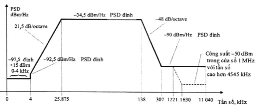
The bandwidth is defined as the range from 25.875 to 138 kHz and is the widest band that can be used. The limits defined within this bandwidth also apply to narrower bands used.
Figure 1 shows the limited frequency spectrum mask for the transmitted signal. The low-frequency cutoff band is frequencies below 25.875 kHz and the POTS band, while the high-frequency band is frequencies above 138 kHz.
Frequency Band f (kHz)
|
Equation of straight line (dBm/Hz) |
0 < f ≤ 4 |
|
-97.5, with maximum power in the 0 to 4 kHz band being +15 dBm |
4 < f ≤ 25.875 |
|
-92.5 + 21.5 x log(f/4) |
25.875 < f ≤ 138 |
|
138 < f ≤ 307 |
-34,5 |
|
-34.5 - 48 x log(f/138) |
307 < f ≤ 1221 |
|
1221 < f ≤ 1630 |
-90 |
|
-90 peak, with maximum power in the [f, f + 1 MHz] window being (-90 - 48 x log(f/1221) + 60) dBm |
1630 < f ≤ 11040 |
|
-90 peak, with maximum power in the [f, f + 1 MHz] window being -50 dBm |
NOTE 1 - All PSD measurements use 100 Ω impedance; total voice band power measurements use 600 Ω impedance. |
|
NOTE 2 - PSD values and frequencies at breakpoints are accurate; slope values are approximated. NOTE 3 - Peak PSD must be measured with a 10 kHz resolution bandwidth for frequencies above 25.875 kHz. NOTE 4 - Power in the sliding 1 MHz window is measured with a 1 MHz bandwidth starting from the measured frequency. NOTE 5 - The jump in the PSD mask at 4 kHz to satisfy the V.90 recommendation requirements. Initially, the PSD mask continued using a 21-dB/octave slope below 4 kHz and reached a bottom of -97.5 dBm/Hz at 3400 Hz. This may not satisfy the V.90 recommendation requirements, therefore, the bottom value was extended to 4 kHz. NOTE 6 - All PSD and power measurements must be performed at the U-C interface (see Figures 2 and 3). Figure 4 - ADSL terminal equipment transmission PSD mask |
|
Measurement method: according to Section 3.8 of this standard.
2.2.1.2 Response and PSD in the bandwidth
There are three PSD masks for the ADSL terminal equipment transmitted signal, depending on the type of signal being transmitted. The PSD level must not exceed the maximum PSD bandwidth transmission level throughout the entire bandwidth, determined as follows:
+ 1 dB, for signals during channel initialization phase to recovery phase;
- OAM REFPSDus
- + 1 dB, during the remaining initialization phase starting from the test equipment phase; MAXNOMPSDus - PCBus
- + 3.5 dB, in the transmission state. Table 1 - Control parameters of ADSL terminal equipment
Default value
|
Parameter |
-38 dBm/Hz |
|
Physical layer |
32 |
|
OAM |
12.5 dBm |
|
NOMPSDus |
12.5 dBm |
|
NSCus |
Group delay change in the bandwidth must not exceed 50 ms. |
Maximum PSD bandwidth transmission level allowed for non-ideal filter effects is 1 dB.
Measurement method: according to Section 3.1 of this standard.
2.2.1.3 Total transmitted power
There are three different PSD masks for the ADSL terminal equipment transmitted signal, depending on the type of signal being transmitted (see 2.2.1.1). In all cases:
- The total transmitted power in the voice band, measured at the U-R interface, and transmitted to the PSTN network interface must not exceed +15 dBm (measurement method according to ITU-T Rec. G.996.1);
- The total transmitted power across the entire bandwidth must not exceed 0.5 dB more than (MAXNOMATPus - PCBus) to account for implementation discrepancies, and must not exceed 13.0 dBm.
- The total transmitted power in the frequency range from 0 to 11.040 MHz must not exceed 0.8 dB more than (MAXNOMATPus - PCBus) to account for excess transmission power in the bands and implementation discrepancies.
Measurement method: according to Section 3.2 of this standard.
2.2.2 Electrical characteristics
2.2.2.1 Determination of impedance states
The source and load impedances of ADSL terminal equipment must comply with the following provisions, where Zin and Z
are the source and load impedances in the active state; ZProvincial People's Committees set specific prices S-hinh cơ L-hare the source and load impedances in the high-impedance state must be greater than the corresponding impedances Z S-hi. Equipment suppliers must select ZANNEX I.A[31] greater than ZProvincial People's Committees set specific prices S-hinh cơ by a specific value.are the source and load impedances in the high-impedance state must be greater than the corresponding impedances Z S-hi. Equipment suppliers must select ZANNEX I.A[31] greater than impedances ZProvincial People's Committees set specific prices S-hinh cơ a defined value.
The following requirements for ADSL terminal equipment allow multiple ADSL terminal devices to be installed on the same pair of wires, although only one ADSL terminal device may be operational at any given time. The parameters and measurement procedures are specified in Section 2.2.2.4.
In each impedance state defined in Table 2, the ADSL terminal equipment transmitter block must meet the ADSL terminal equipment PSD mask specified in Section 2.2.1.1.
Table 2 - Impedance States of ADSL Terminal Equipment
|
State of ADSL Terminal Equipment |
Source Impedance |
Load Impedance |
|
Unpowered |
ZProvincial People's Committees set specific prices-hi |
Znh cơ-hi |
|
Not Ready (Powered but the receiving and transmitting devices are not active) |
ZProvincial People's Committees set specific prices-hi |
Znh cơ-hi |
|
Non-operational (Powered but the transmitting device is not active and the receiving device is active to detect C-TONES signals) |
ZProvincial People's Committees set specific prices-hi |
Znh cơ-hi |
|
Activities (Powered with both the receiving and transmitting devices active and initializing or in transmission state) |
ZProvincial People's Committees set specific prices |
Znh cơ |
Measurement Method: as specified in Section 3.4 of this standard.
2.2.2.2. Requirements for POTS Voltage and Current
Electrical characteristics must be met when the POTS loop current has a value from 0 mA to 100 mA, and the loop voltage is as follows:
- DC voltage ranging from 0 V to -60 V.
- Ringing signals not exceeding 103 V rms at some frequency within the range of 20 to 30 Hz with a DC component ranging from 0 V to -60 V.
2.2.2.3. Characteristics of ADSL Terminal Equipment in Operational StateANNEX I.A[31]for ADSL terminal equipment in Operational State
2.2.2.3.1. DC Characteristics
The DC input impedance of the ADSL terminal equipment at the U-R interface must be greater than or equal to 5 MW.
NOTE - The most common installation method for filters in splitters is to connect low-pass and high-pass filters in parallel at the U-R port. In this configuration, the high-pass filter will block the DC component using capacitors.
2.2.2.3.2. Characteristics in the Voice Band - Input Impedance
The imaginary component of the input impedance of the ADSL terminal equipment, measured at the U-R interface, in the frequency range from 0 kHz to 4 kHz must have a value equivalent to a capacitor ranging from 20 nF to 34 nF (approximately an impedance from 1.1 kW to 2.0 kW at 4 kHz) for ADSL terminal equipment with integrated splitters having high-pass filters (i.e., DC-blocking capacitors of 120 nF are integrated with ATU-R).
2.2.2.3.3. Characteristics in the ADSL Band - Longitudinal Balance
Longitudinal balance at the U-R interface must be greater than 50 dB in the frequency range from 30 kHz to 11,104 kHz.
If the HPF part of the POTS splitter is integrated into the ATU, longitudinal balance measurements in the specified frequency band need to be performed as shown in Figure 5. When both the LPF and HPF parts of the POTS splitter are integrated into the ATU, longitudinal balance measurements in the specified frequency band must be conducted with the POTS interfaces connected to the ZTR impedance, as illustrated in Figure 6.
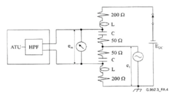
Figure 5 - Method for Measuring Longitudinal Balance in the Frequency Range Greater Than 30 kHz (HPF Integrated in ATU)
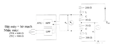
Figure 6 - Method for Measuring Longitudinal Balance in the Frequency Range Greater Than 30 kHz (HPF and LPF Integrated in ATU)ầThis level of balance needs to be measured both with and without DC bias voltage applied to the device under test, in both operational and idle states. In certain cases, the bias voltage may be higher or lower than a specific value, however, it must be sufficiently large to identify issues related to DC bias voltage balance. The bias voltage must be connected through inductors with good impedance matching. The impedance of these inductors must be ≥ 5,000 jW in the specified frequency range. Additional 200 W resistors must be added to ensure safety. organize credit institutions, foreign bank branches are responsible for organizing the implementation of this Circular.Capacitors are included in the measurement circuit to block large DC currents through the 50 W resistors. The impedance of these capacitors must be ≤ |-0.5j W| in the specified frequency range.
The inductors and capacitors in the measurement circuit must be impedance matched so as not to affect the measurement results. When the ratio between the impedance of the inductor and capacitor relative to the 50 W resistor used is high, the impedance matching requirement is lower.
Impedance matching of the inductors is usually easier to achieve by using a two-wire coil on a single core to create a balanced impedance pair. It must be ensured that no resonance occurs in the measurement frequency range. Two inductors (of different sizes) connected in series may be required to meet this requirement when the measurement is a wideband measurement. It is important to ensure that in DC current measurements, saturation does not occur in the inductors. At the same time, it should be noted that some types of capacitors change their value with the applied voltage, generally high-quality plastic types are suitable.
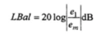
Longitudinal balance (LBal) is determined by the formula:
= input longitudinal voltage (relative to ground at the station or ATU ground);
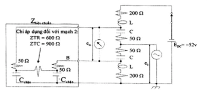
= measured voltage across the terminating resistor.The measurement circuit must have a higher balance level than the device under test by 20 dB (if the balance level is lower, larger errors will appear in the measurement). To ensure this, the device under test must be replaced with two 50 W resistors and appropriate capacitors as shown in Figure 7. The measurement circuit is properly balanced if the balance level exceeds the required level by 20 dB when the Tip and Ring points are connected in each measurement configuration (Tip with A and Ring with B, and Tip with B and Ring with A) with calibrated impedance. Failure to achieve balance indicates imbalance in the measurement circuit or calibration impedance. An additional resistor must be included in the calibration circuit when the device under test has integrated HPF and LPF as shown in Figure 6. This resistor creates a DC path, thereby preventing the inductors from saturating due to DC currents during testing conditions.Figure 7 - Calibration Circuit
 (1)
(1)
Where:
Average loan repayment period is 10 years;1 Electrical characteristics of ADSL terminal equipment in high impedance state
Average loan repayment period is 10 years;m High impedance state includes unpowered, non-operational, and non-operational impedance states as specified in Table 1.
NOTE - The electrical characteristics of ADSL terminal equipment in high impedance state apply to a single ADSL terminal equipment also to up to three ADSL terminal equipments in high impedance state connected in parallel and to one ADSL terminal equipment in operational state at a given time.
2.2.2.4.1. DC Characteristics
2.2.2.4Electrical characteristics of ADSL terminal equipment in high impedance state
High impedance state includes unpowered, inactive impedance states and inactive impedance states as specified in Table 1.
NOTE - The electrical characteristics of ADSL terminal equipment in high impedance state apply to a single ADSL terminal equipment and may also be applicable to up to three ADSL terminal equipments in high impedance state connected in parallel and to one ADSL terminal equipment in active state at a given time.
2.2.2.4.1. DC Characteristics
The DC input impedance of the ADSL terminal equipment at the U-R interface must be greater than or equal to 5 MW.
Measurement method: according to Section 3.3 of this standard.
2.2.2.4.2. Characteristics within the voice band
a) Insertion loss
The insertion loss of the ADSL terminal equipment in high impedance state must be less than 0.33 dB at 3.4 kHz, and must be less than 1 dB at 12 kHz and 16 kHz. The insertion loss of three ADSL terminal equipments on the same line must be less than 1 dB at 3.4 kHz, and less than 3 dB at 12 kHz and 16 kHz.
b) Insertion loss distortion
The insertion loss distortion of the ADSL terminal equipment in high impedance state, when compared with the insertion loss at 3.4 kHz, must be less than ±0.33 dB in the frequency range from 200 Hz to 4,000 Hz. The insertion loss distortion of three ADSL terminal equipments in the frequency range from 200 Hz to 4,000 Hz must be less than ±1 dB.
c) Intermodulation distortion
A set of four tones, as specified in ITU-T Recommendation O.42, at a level of -9 dBm, when applied to the ADSL terminal equipment in high impedance state, must generate intermodulation distortion components of the second and third order smaller than the received signal level by at least 80 dB and 85 dB respectively.
Measurement method: according to Section 3.6 of this standard.
2.2.2.4.3. Characteristics within the ADSL band
a) Insertion loss
The insertion loss of the ADSL terminal equipment in high impedance state, for the signal received by the active ATU-C, must be less than 0.33 dB at 100 kHz (a frequency within the active ADSL terminal equipment transmission band).
The insertion loss of the ADSL terminal equipment in high impedance state, for the signal received by the active ADSL terminal equipment, must be less than 0.33 dB at 500 kHz (a frequency within the active ADSL terminal equipment reception band).
b) Insertion loss distortion
The insertion loss distortion of the ADSL terminal equipment in high impedance state for the signal transmitted by the active ADSL terminal equipment must be less than 0.33 dB in the frequency range from 25 kHz to 1,104 kHz.
Measurement method: according to Section 3.6 of this standard.
2.2.2.4.4. Characteristics outside the ADSL band
a) Insertion loss
The insertion loss of the ADSL terminal equipment in high impedance state must be less than 0.33 dB at 5 MHz and at 9 MHz.
b) Insertion loss distortion
The insertion loss distortion of the ADSL terminal equipment must be less than ±0.33 dB in the frequency range from 4 MHz to 10 MHz.
Measurement method: according to Section 3.6 of this standard.
TESTING METHODS
ADSL2+ devices must meet all requirements in Section 2.2 except those specified in Sections 2.3.1 and 2.3.2.
2.3.1. Functional characteristics of the ADSL terminal equipment
2.3.1.1. Frequency spectrum mask of the transmitted signal from the ADSL terminal equipmentDeputy ministers of ministerial-level agencies,The bandwidth is the frequency band from 25.875 kHz to 138 kHz and is the widest band that can be used. The limits defined in this bandwidth also apply to narrower bands used.
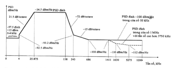
Figure 8 shows the frequency spectrum mask limit for the transmitted signal. The low-frequency cutoff band includes frequencies lower than 25.875 kHz and includes the POTS band, while the high-frequency band includes frequencies higher than 138 kHz.
The PSD (dBm/Hz) level
|
Frequency (kHz) |
100 Hz |
Network termination |
|
0 |
-97,5 |
interpolation |
|
4 |
-97,5 |
interpolation |
|
4 |
-92,5 |
interpolation |
|
10 |
Additionally, the PSD mask must meet the following requirements: |
10 kHz |
|
25,875 |
- 34,5 |
10 kHz |
|
138 |
- 34,5 |
10 kHz |
|
243 |
- 93,2 |
10 kHz |
|
686 |
-100 |
10 kHz |
|
5 275 |
-100 |
10 kHz |
|
12 000 |
-100 |
10 kHz |
|
NOTE 2 - The PSD values and frequencies at the breakpoints are accurate; the slope values are approximated. These points are connected by straight linear lines on the dB/log(f) graph. |
||
|
Frequency (kHz) |
100 Hz |
Network termination |
|
1 411 |
-100 |
2.2. Measurement Methods |
|
1 630 |
-110 |
2.2. Measurement Methods |
|
5 275 |
-112 |
2.2. Measurement Methods |
|
12 000 |
-112 |
2.2. Measurement Methods |
|
NOTE 2 - PSD values and frequencies at breakpoints are accurate; slope values are approximated. NOTE 3 - MBW is the measured bandwidth. The MBW value is specified for each breakpoint frequency f applicable to all frequencies satisfying fANNEX I.A[31] < f ≤ fANNEX I.A[31] , where f9. Travel distance is the distance traveled without using mechanical means (cars, motorcycles, motorboats) to reach locations for implementing technical forest management measures and patrolling to protect forests.is the next specified breakpoint frequency.9. Travel distance is the distance traveled without using mechanical means (cars, motorcycles, motorboats) to reach locations for implementing technical forest management measures and patrolling to protect forests. NOTE 4 - Power in the 1-MHz sliding window is measured with a 1-MHz bandwidth, starting from the measurement frequency, i.e., the power in the window [f, f + 1 MHz] must comply with the specification at frequency f. |
||
|
NOTE 6 - All PSD and power measurements must be performed at the U-R interface. NOTE 6 - All PSD and power measurements must be performed at the U-C interface (see Figures 2 and 3). Figure 8 - Transmitted PSD mask |
||
2.3.1.2. Response and PSD within the bandwidthDeputy ministers of ministerial-level agencies,The bandwidth is the frequency band from 25.875 kHz to 138 kHz and is the widest band that can be used. The limits defined in this bandwidth also apply to narrower bands used.
2.2.1.2 Response and PSD in the bandwidth
There are three different PSD masks for the transmitted signal of the ADSL terminal equipment, depending on the type of signal being transmitted. Throughout the entire bandwidth, the transmitted PSD level must not exceed the maximum PSD bandwidth level, determined as follows:amend+ 1 dB during the remaining initialization phase, from the device test run phase;
+ 3.5 dB during the transmission state.
- OAM REFPSDus
- + 1 dB, during the remaining initialization phase starting from the test equipment phase; Table 3 - Control parameters of the ADSL terminal equipment
- + 3.5 dB, in the transmission state. Value
-38 dBm/Hz
|
Parameter |
Group delay variation within the bandwidth must not exceed 50 ms.councillORS m2.3.1.3. Total transmitted powerc đ ||| c đcouncillORSealth |
|
Physical layer |
32 |
|
OAM |
There are three different PSD masks for the transmitted signal of the ADSL terminal equipment, depending on the type of signal being transmitted (Section 2.3.1.1). In all cases: |
|
NOMPSDus |
There are three different PSD masks for the transmitted signal of the ADSL terminal equipment, depending on the type of signal being transmitted (Section 2.3.1.1). In all cases: |
|
NSCus |
Group delay change in the bandwidth must not exceed 50 ms. |
- The total transmitted power in the voice band, measured at the U-R interface and transmitted to the POTS interface, must not exceed +15 dBm (measurement method according to ITU-T Rec. G.996.1).
Measurement method: according to Section 3.1 of this standard.
2.2.1.3 Total transmitted power
- The total transmitted power across the entire bandwidth must not exceed 0.5 dB more than (MAXNOMATPus - PCBus) to account for implementation discrepancies and must not exceed 13.0 dBm.
- The total transmitted power in the frequency range from 0 to 12 MHz must not exceed 0.8 dB more than (MAXNOMATPus - PCBus) to account for excess transmission power in the bands and implementation discrepancies.
2.3.2. Electrical characteristics
The requirements in Section 2.2.3 (excluding the longitudinal conversion loss parameter) must be met in the frequency band up to 1,104 kHz in the frequency band up to 2,208 kHz.
The ADSL terminal equipment must have a minimum longitudinal conversion loss (LCL) of 50 dB in the frequency range from 30 kHz to 1,104 kHz.
2.2.2 Electrical characteristics
The ADSL terminal equipment must have a minimum longitudinal conversion loss (LCL) of 40 dB in the frequency range from 1,104 kHz to 2,208 kHz.
3.1. Frequency response
Figure 9 - Configuration for measuring frequency response
Connect the equipment as shown in Figure 9.
3. MEASUREMENT METHODS
Set the spectrum analyzer to receive signals within the bandwidth with a resolution bandwidth of 10 kHz and a video bandwidth of 100 Hz. Resistance R = 100 Ω.amend+ 1 dB during the remaining initialization phase, from the device test run phase;
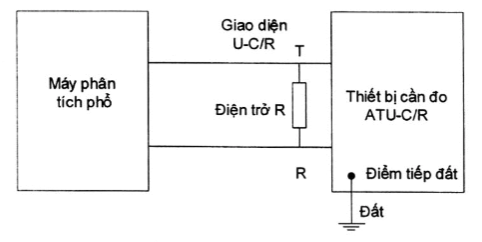
Evaluate the signal against the transmitted PSD mask.No. allocated
3.2. Total transmitted power
Connect the equipment as shown in Figure 10.
Set the spectrum analyzer to receive signals within the bandwidth with a resolution bandwidth of 1 kHz and a video bandwidth of 100 Hz.
Record the frequency values corresponding to the nominal power reduced by 3 dB. Bandwidth is calculated as the difference between the two frequency values.
Use a filter with a bandwidth equal to the value calculated in the previous step.
Measure and record the total signal power with the final resistance R = 100 Ω.
Figure 10 - Configuration for measuring total transmitted power
Use a filter with a bandwidth equal to the value calculated in the previous step.
Figure 11 - Configuration for measuring DC resistance
Connect the equipment as shown in Figure 11.
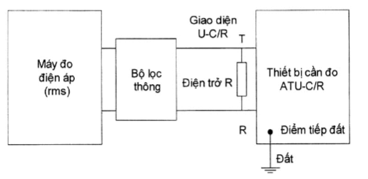
Figure 10 - Configuration for measuring total transmitted power
3.4. Impedance
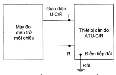
Figure 11 - Configuration for measuring DC resistance
Connect the equipment as shown in Figure 11.
Measure the direct current resistance before powering the device to be measured, when powered but the transmission and reception equipment are not operating, when powered but the transmission equipment is not operating and the reception equipment is operating to detect C-TONES signals, or when powered with the transmission and reception equipment operating and initiating or in a transmission state.
3.5. Crosstalk balance
Connect the equipment as shown in Figure 12.
Measure impedance when powered with the transmission and reception equipment operating and initiating or in a transmission state.
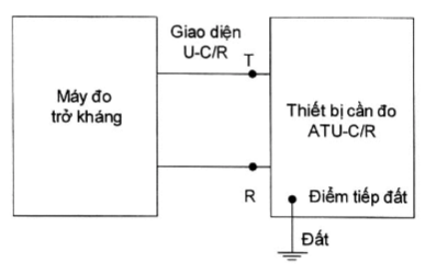
Figure 12 - CConfiguration for measuring impedance
3.6. NEXT attenuation and NEXT distortion
See Section 2.2.2.3.3.
3.7. Upstream transmission rate (or downstream transmission rate)
3.6.1. Insertion loss and insertion loss distortion in the voice band
Connect the equipment as shown in Figure 13.
Measure insertion loss/insertion loss distortion within the frequency range from 0.2 to 4 kHz; at frequencies 12 and 16 kHz before powering the device to be measured, when powered but the transmission and reception equipment are not operating, or when powered but the transmission equipment is not operating and the reception equipment is operating to detect C-TONES signals.
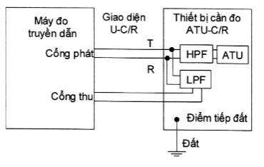
(a) HPF and LPF are integrated
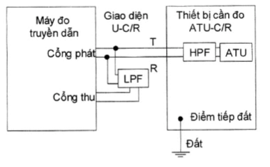
(b) Only HPF is integrated
Figure 13 - Configuration for measuring insertion loss and insertion loss distortion in the voice band
3.6.2. Insertion loss and insertion loss distortion in the ADSL band and outside the ADSL bandamendng tần ADSL và ngoài bamendwithin ADSL frequency band
Connect the equipment as shown in Figure 14.
Measure insertion loss/insertion loss distortion within the frequency range from 25 to 1104 kHz; and from 4 to 10 MHz before powering the device to be measured, when powered but the transmission and reception equipment are not operating, or when powered but the transmission equipment is not operating and the reception equipment is operating to detect C-TONES signals.
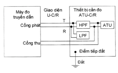
(a) HPF and LPF are integrated
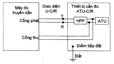
(b) Only HPF is integrated
Figure 14 - Configuration for measuring insertion loss and insertion loss distortion in the ADSL band and outside the ADSL bandamendwithin ADSL frequency band and outside ADSL frequency band
3.8. PSD mask
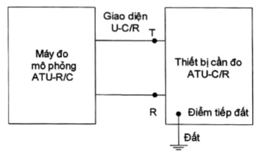
Figure 15 - Configuration for measuring upstream (or downstream) transmission rate and PSD maskên (or downstream data rate) and PSD mask
Connect the equipment as shown in Figure 15.
Set the measurement simulator to the ATU-C simulation mode to measure the upstream rate (or downstream rate).
Preface
Connect the equipment as shown in Figure 15.
Set the measurement simulator to the ATU-C simulation mode to measure the PSD mask.
5. RESPONSIBILITIES OF ORGANIZATIONS AND INDIVIDUALS
ADSL terminal devices of types ADSL2 and ADSL2+ within the scope specified in Section 1.1 must comply with the technical requirements stipulated in this Standard.
5. RESPONSIBILITIES OF ORGANIZATIONS AND INDIVIDUALS
Organizations and individuals related have the responsibility to implement conformity certification and announce conformity of ADSL terminal devices of types ADSL2 and ADSL2+, and are subject to inspection by state management agencies according to current regulations.
6. IMPLEMENTATION ORGANIZATION
6.1. The Telecommunications Authority and Provincial Departments of Information and Communications are responsible for organizing guidance and implementing management of ADSL terminal devices of types ADSL2 and ADSL2+ according to this Standard.
6.2. In case the provisions set out in this Standard are changed, supplemented, or replaced, they shall be implemented according to the new document./.
QCVN 110:2017/BTTTT was compiled by the Post and Telecommunications Science and Technology Institute, reviewed by the Department of Science and Technology, and promulgated along with Circular No. 24/2017/TT-BTTTT dated October 17, 2017.
[1] ITU-T Recommendation G.992.3 (04/2009), Asymmetric digital subscriber line transceivers 2 (ADSL2).
[2] ITU-T Recommendation G.992.5 (01/2009), Asymmetric digital subscriber line transceivers - Extended bandwidth ADSL2 (ADSL2+).
Văn bản gốc (PDF)
Bản đồ quan hệ
Bấm vào một văn bản để mở. Viền đỏ = quan hệ làm thay đổi hiệu lực.