
These regulations set forth technical requirements concerning safety, environmental protection, and turning radius for city bus vehicles. The main contents include: 1) General design and structural requirements; 2) Passenger protection measures; 3) Testing and inspection methods; 4) Implementation organization. These regulations apply to city bus vehicles produced, assembled, or imported from January 1, 2017.
적용 범위
City bus vehicles
핵심 사항
- Design and structural requirements such as overall dimensions, distance between rows of seats, entry and exit doors, ventilation systems, air conditioning...
- Passenger protection measures such as rearview mirrors, windshields, lighting, roofless vehicle enclosures...
- Testing and inspection methods according to Circular No. 30/2011/TT-BGTVT and Circular No. 54/2014/TT-BGTVT
- The implementation timeline for these standards begins on January 1, 2017 for new vehicles, while existing vehicles certified prior to this date have a transition period of 18 months.
- The turning radius of the vehicle must not exceed the prescribed limit.
🌐 이 문서의 사회적 영향
- Enhance passenger safety when using public transportation services
- Minimize environmental pollution from transport activities
- Standardize the quality inspection procedures for motor vehicles
❓ 자주 묻는 질문
To which types of vehicles do these regulations apply?
They apply to city bus vehicles produced, assembled, or imported.
When does the implementation of these regulations begin?
For new vehicles from January 1, 2017. For existing vehicles certified prior to this date, there is a transition period of 18 months.
What are the main requirements of these regulations?
They include design and structural requirements, passenger protection measures, testing and inspection methods, and implementation organization.
전문
|
MINISTRY OF TRANSPORTATION _________ Number: 90/2015/TT-BGTVT |
SOCIALIST REPUBLIC OF VIETNAM Independence - Freedom - Happiness _______________________ Hanoi, December 31, 2015 |
CIRCULAR
Issuing National Technical Regulations on quality, technical safety, and environmental protection for specialized motorcycles
environmental protection for city buses
__________________
Pursuant to the Law on Standards and Technical Regulations dated June 29, 2006;
Based on Decree No. 132/2008/NĐ-CP dated December 31, 2008 of the Government detailing implementation of certain provisions
Pursuant to Decree No. 107/2012/NĐ-CP dated December 20, 2012 of the Government stipulating the functions, tasks, powers, and organizational structure of the Ministry of Transport;
The Minister of Transport issues this Circular amending and supplementing certain articles of Circular No. 29/2018/TT-BGTVT dated May 14, 2018, issued by the Minister of Transport on quality inspection, technical safety, and environmental protection for railway transportation vehicles, and Circular No. 18/2019/TT-BGTVT dated May 20, 2019, issued by the Minister of Transport guiding the implementation of Decree No. 139/2018/NĐ-CP dated October 8, 2018, of the Government on business operations of vehicle inspection services.
The Minister of Transport issues this Circular on national technical regulations regarding quality, safety technical standards, and environmental protection for city buses.
Article 1. This Circular promulgates national technical regulations regarding quality, safety technical standards, and environmental protection for city buses.
Code: QCVN 10:2015/BGTVT.
Article 2. This Circular takes effect from July 1, 2016. It abolishes Clause 2 of Article 1 of Circular No. 56/2011/TT-BGTVT dated November 17, 2011 issued by the Minister of Transport concerning the issuance of six national technical regulations on road motor vehicles.
Article 3. The Director of the Ministry's Office, the Inspector General, Heads of Departments, the Director of the Vietnam Motor Vehicle Inspection Agency, Heads of agencies, units, and individuals related to this Circular shall be responsible for its implementation./.
|
Place of Receipt: |
THE MINISTER |
QCVN 10:2015/BGTVT
NATIONAL TECHNICAL REGULATION ON QUALITY, SAFETY TECHNICAL STANDARDS AND ENVIRONMENTAL PROTECTION FOR CITY BUSES
National technical regulation on safety and environmental protection for urban bus
Foreword
QCVN 10:2015/BGTVT was compiled by the Vietnam Motor Vehicle Inspection Agency, reviewed by the Ministry of Science and Technology, and issued by the Minister of Transport pursuant to Circular No. 90/2015/TT-BGTVT dated December 31, 2015.
QCVN 10:2015/BGTVT replaces QCVN 10:2011/BGTVT.
NATIONAL TECHNICAL REGULATION ON QUALITY, SAFETY TECHNICAL STANDARDS AND ENVIRONMENTAL PROTECTION FOR CITY BUSES
National technical regulation on safety and environmental protection for urban bus
Chapter 1. GENERAL PROVISIONS
1.1. Scope of Application
This standard specifies technical requirements and procedures for inspecting quality, safety technical standards, and environmental protection for city buses with 17 seats or more (hereinafter referred to as "vehicles").
1.2. Applicability
This standard applies to production facilities, assembly plants, organizations, and individuals importing vehicles and vehicle parts, as well as management, inspection, testing, and certification bodies related to quality, safety technical standards, and environmental protection for city buses with 17 seats or more.
1.3. Definitions
This standard uses terms defined in National Technical Regulation QCVN 09:2015/BGTVT "National Technical Regulations on Quality, Safety Technical Standards, and Environmental Protection for Motor Vehicles" (hereinafter referred to as "QCVN 09:2015/BGTVT") and the following terms and definitions:
1.3.1. City Bus (Urban bus) is a passenger vehicle designed and equipped for use in cities and suburbs; it has seating and standing areas for passengers and allows passengers to move around during frequent stops and parking.
1.3.2. Articulated City Bus (Articulated bus) is a city bus consisting of two or more rigid sections connected by a pivot joint, allowing passengers to move between sections. The connection or disconnection of sections can only be done at a workshop (hereinafter referred to as "articulated bus").
1.3.3. Double-Deck City Bus (Double-deck bus) is a city bus with two floors, providing space for passengers on both floors but not allowing standing on the upper floor (hereinafter referred to as "double-deck bus"). Roofless City Bus (Urban bus without roof)
1.3.4. is a city bus without a roof covering the entire floor or part of the floor. For double-deck buses, only the upper floor may lack a roof. If any floor lacks a roof, whether entirely or partially, standing space for passengers on that floor is not allowed (hereinafter referred to as "roofless bus").(*) Intercommunication Staircase (Intercommunication staircase)
1.3.5. is the staircase connecting the first and second floors of a double-deck bus (hereinafter referred to as "staircase"). Half-Staircase (Half-Staircase)
Note: (*) is a type of staircase leading from the second floor to an emergency exit door of a double-deck bus, which is hereinafter referred to as the "emergency staircase".
1.3.6. Contrast (Contrast) is the difference in light reflection from the surfaces of various parts or equipment of the vehicle due to differences in color.
1.3.7. Optical Device (Optical device) includes mirrors and screens arranged in a closed chain to allow the driver to observe areas within the vehicle.
1.3.8. Seat (Seat) is a seat designated for passengers, excluding those for the driver or service personnel.
1.3.9. Step Depth (Deep) is the distance from the outer edge of the step to the vertical plane between the step and the adjacent step above or the floor, measured horizontally.
1.3.10. Doorway Area (Doorway area) is the area including points up to one meter away from the outer edge of the door frame, measured horizontally.
1.3.11. External Step (External step) is the first step of the entrance or exit door counted from the parking surface.
1.3.12. Floor (Floor) is the part of the body of the vehicle that supports standing passengers, seated passengers' feet, the driver, service personnel, and the seat frame.
1.3.13. Access Passage (Access passage) is the path through the door to the longitudinal aisle.
1.3.14. Double or Multiple Window (Double or multiple window) is an emergency exit window divided into two or more sections by one or more straight lines (or vertical planes), each section having dimensions and access ensuring compliance with the requirements of a regular emergency exit window.
1.3.15. Driver's Compartment (Driver’s compartment) is the space reserved for the driver, except in emergencies, containing the driver's seat, steering wheel, mechanisms, switches, control devices, and other equipment serving driving and controlling the vehicle's operations.
1.3.16. Passenger's Compartment (Passenger’s compartment) is the space for passenger use. Bathrooms, kitchens, bars (if any) are not included in the passenger's compartment.
1.3.17. Total Floor Area (Total floor area) used as a basis for calculating and determining the minimum preferred floor area,
1.3.18. is the total floor area of the vehicle, or for double-deck buses, the sum of the floor area of the first floor minus the driver's compartment, wheel arches, stairwell, internal staircase, or any designated spaces for luggage. 2. TECHNICAL SAFETY REQUIREMENTS AND ENVIRONMENTAL PROTECTIONCity buses must meet the requirements specified in National Technical Regulation QCVN 09:2015/BGTVT.
2. TECHNICAL SAFETY REQUIREMENTS AND ENVIRONMENTAL PROTECTION
City buses must comply with the requirements set forth in Technical Regulation QCVN 09 : 2015/BGTVT "National Technical Regulation on Safety Technical Quality and Environmental Protection for Motor Vehicles"; and the specific requirements set forth in this Standard. Additionally, for city buses designed for people with disabilities to access and use, technical requirements regarding accessibility must comply with Standard QCVN 82 : 2014/BGTVT. "National Technical Regulation on City Buses for People with Disabilities to Access and Use";.
2.1 Technical parameters
2.1.1 The percentage of weight distributed on the steering axle (or steering axles) shall not be less than 20% of the vehicle's weight when unloaded and not less than 25% of the vehicle's weight when fully loaded. For articulated vehicles, this ratio is determined for the first trailer and shall not be less than 20% in both unloaded and fully loaded conditions.
2.1.2 Turning radius: As specified in the Appendix of this Standard.
2.1.3 The maximum gradient that the fully loaded vehicle can overcome shall not be less than 20%; for articulated vehicles, this gradient shall not be less than 12%.
2.1.4 There shall be no cargo or luggage structure on the roof of the vehicle.
2.1.5 Passenger floor area S0 is the entire area of the vehicle floor minus the following areas:
- Driver's cabin area;
- Area of the boarding steps and any other area with steps having a depth of less than 300 mm;
- Area swept by the door and its mechanical components during opening and closing;
- Connection area between trailers (for articulated vehicles) as specified in Section 2.5.9.6, which passengers cannot access;
- Area of stairways, emergency exits, and stairs;
- Area reserved for kitchen, bar, and toilet (if any) operations.
2.1.6 Standing passenger floor area S1 is calculated by subtracting the following areas from the passenger floor area S0 :
- Areas where the floor has a slope greater than 8%;
- All areas of the floor where standing passengers cannot reach when all seats are occupied;
- Areas where the height from the floor is less than the height of the aisle (excluding handrails when determining this height);
- Floor area in front of the driver's seat plane perpendicular to the longitudinal axis of the vehicle passing through the center of the seat cushion;
- An area of 250 mm in front of each seat. This dimension reduces to 225 mm if the seat is installed such that its symmetry plane is perpendicular to the longitudinal axis of the vehicle;
- Any floor areas outside those mentioned above that cannot accommodate a rectangle measuring 400 mm x 300 mm;
- Passenger floor area at the second level of two-level vehicles;
- Wheelchair storage area.
2.1.7 The number of seats at each level of the vehicle shall not be less than the square meters of the passenger and service staff floor area at that level, rounded down to the nearest whole number, and may be reduced by up to 10% for the first level of two-level vehicles.
2.1.8 Determination of the number of seats, standing positions, and wheelchair spaces must follow the principle that all seats, standing positions, and wheelchair spaces are fully utilized.
2.1.9 The total calculated weight of wheelchairs and their users shall be determined according to the manufacturer's specifications but shall not be less than 250 kg.
2.1.10 The overall height of the vehicle without a roof shall not exceed 3.8 m.
2.2 Suspension system
2.2.1 Must withstand the load acting upon it and ensure necessary smoothness when operating on roads. For vehicles equipped with air suspension systems, they must be installed according to the manufacturer's specifications and shall not leak compressed air.
2.2.2 Components and assemblies of the suspension system must be securely installed and ensure vehicle balance.
2.2.3 The natural frequency of the suspended part of the vehicle in a fully loaded state (determined according to the method specified in Appendix 1 of Standard QCVN 09:2015/BGTVT) shall not exceed 2.5 Hz.
2.3 Fuel system
2.3.1 Requirements for gasoline or diesel fuel systems
2.3.1.1 No part of the fuel system shall be located within the passenger compartment or the driver's cabin.
2.3.1.2 Components of the fuel system must be installed far enough away from heat sources, wiring, and electrical equipment; the installation position must be at least 300 mm from the exhaust pipe outlet and at least 200 mm from electrical switches and exposed electrical connectors.
2.3.1.3 The fuel tank must be securely installed, at least 600 mm from the front of the vehicle, at least 300 mm from the rear of the vehicle, and shall not protrude beyond the side of the vehicle.
2.3.1.4 The fuel filler neck must be positioned outside the vehicle and shall not protrude beyond the side of the vehicle.
2.3.2 Requirements for liquefied petroleum gas (LPG) or compressed natural gas (CNG) fuel systems and other fuel system requirements
Shall comply with the requirements specified in Standard QCVN 09 : 2015/BGTVT.
2.4 Driver's workspace and field of vision
2.4.1 The driver's cabin must have a structure ensuring safe operation for the driver, unaffected by passengers and luggage while the vehicle is in motion.
2.4.2 The design of the driver's seat, cushion shape, and seat back must ensure comfort and adjustability to allow the driver to achieve the required field of vision as specified in Section 2.4.4.
2.4.3 The arrangement of seats adjacent to the driver (if any) shall not affect the driver's ability to control the vehicle.
2.4.4 Driver's field of vision criteria are illustrated in Figure 1 and specified in Table 1.
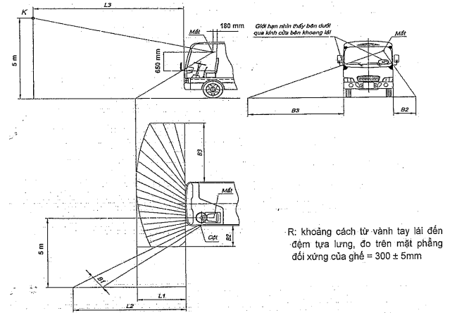
Figure 1 - Driver's field of vision
Table 1 - Driver's field of vision criteria
No.
Index
Code
Value (m)
1
Unseen section length
L1
≤ 3,0
2
The left boundary of the road section obscured by the column at the front edge
L2
≤ 7,0
3
The distance between the projection of the vehicle's front end and the projection of point K on the road surface (point K belongs to the upper sightline ray, higher than the road surface by 5 meters)
L3
≤ 10,0
4
The width of the road section not visible due to being obscured by the column
B1
≤ 1,2
5
The distance from the left boundary of the road section not visible to the left side of the vehicle
B2
≤ 2,0
6
The distance from the right boundary of the road section not visible to the right side of the vehicle
B3
≤ 6,0
2.4.5. If the driver's cabin does not have a roof, the driver must be protected from strong wind, rain, and dust.
2.4.6. If the driver's cabin is separate and not connected to the passenger compartment, the driver's cabin must have two exits that are not arranged on the same side of the vehicle; if one of these exits is a window, it must comply with the regulations for emergency exit windows specified in Section 2.5.4.
2.5. Passenger Compartment (Passenger Compartment)
2.5.1. Must be designed to ensure safety for passengers during operation.
2.5.2. The useful area allocated for each standing passenger shall not be less than 0.125 m2. The space for standing passengers is the space above the floor area designated for standing passengers as specified in Section 2.1.6 and must meet the following requirements:
+ Useful height shall not be less than 1800 mm;
+ Useful width shall not be less than 300 mm;
+ Shall have handrails and handholds for standing passengers.
2.5.3. Passenger Doors and Stairs
2.5.3.1. The minimum useful size of passenger doors is specified in Table 2.
2.5.3.2. Number of passenger doors:
a) The minimum number of passenger doors is specified in Table 3;
b) For articulated vehicles, the minimum number of passenger doors for the leading trailer is two, and for the trailing trailer is one;
c) Double doors are considered equivalent to two doors when calculating the number of passenger doors;
d) For double-decker vehicles:
- Each stairway is considered as one entrance door for the second level;
- If the number of passengers on the second level exceeds 50, the vehicle must have two stairways or at least one stairway and one emergency exit stairway.
Table 2 - Minimum Useful Size of Passenger Doors
Number of Passengers
Minimum Useful Door Size (mm)
Single Door
Double Door
Width (1)
Height
Width (1)
Height
From 17 to 40 passengers
650
1700
1200
1700
More than 40 passengers
650
1800
1200
1800
Note:
(1) This measurement is reduced by 100 mm when measured at the height of the highest protrusion of the door handle.
Table 3: Minimum Number of Passenger Doors
Number of Passengers
17 to 45
46 to 90
more than 90
Minimum Number of Passenger Doors
1
2
3
2.5.3.3. Other Requirements
a) Passenger doors must be located on the sides of the vehicle;
b) There must be at least one passenger door on the right side of the vehicle according to its forward direction and located in the front half of the vehicle (except for city buses BRT - Bus Rapid Transit or similar transport types);
c) Special doors may be installed at the rear of the vehicle or on the sides of the vehicle to facilitate wheelchair access;
d) Passenger doors must be easily opened from both inside and outside the vehicle and cannot open automatically when locked; they must be constructed to ensure passenger safety under normal operating conditions.
2.5.3.4. Requirements for the Coupling Area of Articulated Vehicles:
a) Gap(1) shall not be covered between the floor of the rigid trailer and the floor of the swivel platform or a mechanism with equivalent functionality as follows:
- Not greater than 1 cm: When all wheels are on the same plane;
- Not greater than 2 cm: When the wheels of the adjacent axle at the coupling are parked on a surface 15 cm higher than the parking surface of the other axles' wheels.
Note:(1) Measured when the vehicle is unloaded and parked on a horizontal plane.
b) Difference in height between the floor of the rigid trailer and the floor of the swivel platform measured at the coupling:
- Not greater than 2 cm: When all wheels are on the same plane;
- Not greater than 3 cm: When the wheels of the adjacent axle at the coupling are positioned 15 cm higher than the parking surface of the other axles' wheels.
2.5.4. Emergency Exit Doors
The vehicle must have emergency exit doors; passenger doors shall not be counted as emergency exit doors. Emergency exit doors on the vehicle must comply with the following requirements:
2.5.4.1. Minimum size of emergency exit doors:
Width x Height = 550 mm x 1200 mm.
2.5.4.2. Emergency exit doors can be easily opened from the inside or outside when the vehicle is stationary. Emergency exit doors can be locked from the outside but must ensure that they can always be opened from the inside using a standard opening mechanism in all circumstances.
2.5.4.3. Emergency exit doors shall not be sliding doors or doors that require energy (electricity, compressed air...) to operate.
2.5.4.4. Any mechanism or device to open an emergency exit door from the outside (emergency exit door on the first level for double-decker vehicles) must be within a height range of 1000 mm to 1500 mm from the ground surface and no more than 500 mm away from the emergency exit door. Any mechanism or device to open an emergency exit door from the inside must be within a height range of 1000 mm to 1500 mm from the top of the floor or the nearest step to the mechanism or device and no more than 500 mm away from the emergency exit door. This requirement does not apply to mechanisms or devices located in the driver's cabin.
2.5.4.5. Emergency exit doors installed on the side of the vehicle must be hinged at the front edge of the door facing the direction of travel and must open outward. It is permissible to install a latch strap, chain, or other limiting devices if they do not obstruct the opening of the emergency exit door and still maintain a minimum opening angle of 100°. If the path to the emergency exit door can easily be brought to the door, the minimum opening angle requirement of 100° does not apply.
2.5.4.6. Emergency exit doors must be protected against accidental opening. This requirement does not apply to emergency exit doors that are automatically locked when the vehicle travels at a speed greater than 5 km/h.
2.5.4.7. There must be an audible warning device for the driver when the emergency exit door has not been fully closed, and the warning device must activate when there is any movement of the handle or hook from its designated position.
2.5.4.8. Emergency exit windows must have a minimum area of 0.4 m2 and must fit within a rectangle with a height of 500 mm and a width of 700 mm (in this case, the emergency exit window is considered an emergency exit door).
2.5.4.9. The emergency exit window on the rear of the vehicle must comply with the provisions of Clause 2.5.4.8 or must be able to accommodate a rectangular shape with a height of 350 mm and a width of 1550 mm, with the corners of the rectangle rounded with a radius not exceeding 250 mm (in this case, the emergency exit window on the rear of the vehicle shall be considered as an emergency exit).
2.5.4.10. The hinged emergency exit window must open outward from the vehicle.
2.5.4.11. The emergency exit window must be capable of being easily opened from both inside and outside the vehicle through an appropriate mechanism or manufactured using high-strength glass.
2.5.4.12. Emergency exit windows that can be locked from the outside must be constructed so that they can be easily opened at any time from the inside of the vehicle.
2.5.4.13. For emergency exit windows with horizontal hinges installed at the top edge of the door, an appropriate mechanism must be provided to keep the door in a fully open position without obstructing access to the emergency exit window from either inside or outside the vehicle.
2.5.4.14. The lower edge height of the emergency exit window located along the side of the vehicle measured from the floor directly below the emergency exit window (excluding wheel well areas) must not exceed 1200 mm and must not be less than 650 mm for hinged emergency exit windows or 500 mm for emergency exit windows made of high-strength glass.
In the case of hinged emergency exit windows, the lower edge height may be reduced but must not be less than 500 mm if the window is equipped with protective shielding up to a height of 650 mm to prevent passengers from falling out of the vehicle from the window. For windows with such protective shielding, the size of the upper part of the window above the protective shielding must not be smaller than the minimum size specified for emergency exit windows.
2.5.4.15. The minimum number of emergency exits is specified in Table 4.
Table 4 - Minimum Number of Emergency Exits
Number of Passengers(1)
17 ÷ 30
31 ÷ 45
46 ÷ 60
61 ÷ 75
76 ÷ 90
> 90
Minimum number of emergency exits(2)
4
5
6
7
8
9
Note:
(1) For two-deck vehicles or articulated vehicles, the number of passengers refers to the number of passengers, drivers, and service personnel on each deck or each section.
(2) Passenger doors are not counted as emergency exits;
Emergency exits in this table include emergency exits and emergency exit windows.
2.5.4.16. Bathrooms, kitchens, bar counters (if any), and intercarriage areas are not included when calculating the number of emergency exits.
2.5.4.17. Double windows or multi-pane windows are equivalent to two emergency exit windows when they meet the requirements for emergency exit windows.
2.5.4.18. At each emergency exit and emergency exit window, the phrase "EMERGENCY EXIT" or "CỬA THOÁT KHẨN CẤP" or both must be clearly marked together with necessary instructions. Near emergency exit windows made of high-strength glass, tools for breaking the window must be provided.
2.5.4.19. The pathways to emergency exits and emergency exit windows must comply with the provisions of Technical Regulation QCVN 09:2015/BGTVT.
2.5.5. Passenger Seats
2.5.5.1. Seats must be securely installed to ensure safety for passengers when the vehicle is operating on the road under normal conditions.
2.5.5.2. Seat dimensions:
+ Seat width: ≥ 400 mm
+ Seat depth: ≥ 350 mm
+ Seat height (H): 400 ÷ 500 mm
Under the wheel arches and engine hood, seat height may be reduced but must not be less than 350 mm and must ensure passenger comfort.
2.5.5.3. The distance from the back of the cushion of the front seat to the front of the cushion of the rear seat of two adjacent rows of seats (L) must not be less than 630 mm.
2.5.5.4. The distance between the fronts of the cushions of two facing seats (L0) must not be less than 1250 mm.
The distances are specified in Table 5 and illustrated in Figure 2.
Table 5 - Dimensions Between Seats
Unit of measurement: mm
|
LMinimum |
L0 Minimum |
H |
|
630 |
1250 |
400 ÷ 500 |
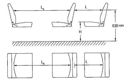
Figure 2 - Dimensions Between Seats
2.5.6. Aisle
- Width: ≥ 400 mm
- Height from floor to ceiling on the aisle:
+ First floor: ≥ 1800 mm
+ Second floor: ≥ 1680 mm
- Slope of the aisle: ≤ 8 %.
- The space on the aisle of the vehicle must be designed and constructed to allow the passage of a test figure consisting of two (02) concentric cylindrical shapes connected by an inverted conical shape. The dimensions of the cylinder are defined as shown in Figure 3.
If the vehicle is permitted to have foldable seats on the aisle, the measurement is taken in the unfolded state for non-automatic folding seats or in the folded state for automatic folding seats when not in use.
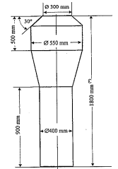
(*) This dimension is 1680 mm for the second-floor aisle clearance check in two-deck vehicles.
Figure 3 - Test Figure for Aisle Clearance
2.5.7. Vehicle Floor
The vehicle floor must be made of non-slip material.
2.5.8. Steps and Other Ramps
2.5.8.1. The surface of the steps must be roughened or coated with friction material to ensure passenger safety when boarding and alighting.
2.5.8.2. The permissible height and depth dimensions for passenger door steps, staircases, emergency exit steps, and other steps within the vehicle are illustrated in Figure 4 and specified in Table 6.
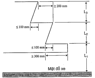
Figure 4 - Height and Depth Dimensions of Steps
Table 6 - Permissible Height and Depth Dimensions for Steps
Unit of measurement: mm
First Step (counted from the ground level)
Passenger Door
Maximum Height (L1)
400
Minimum Depth
300(1)
Emergency Exit Door
Maximum Height (L1)
First Floor
850(2)
Second Floor
1500
Minimum Depth
300
Other Steps
Maximum Height (L2, L3)
250(3)
Minimum Height (L2, L3)
120
Useful Depth(4) Minimum
200
Note:
(1) 200 for vehicles carrying up to 40 passengers;
(2) 700 for single-deck vehicles;
(3) 300 for steps behind the last axle;
(4) Useful depth is determined in the area where the foot can be placed without slipping off the step;
The height of the step from the ground level is determined when the vehicle is in an unloaded state;
The height between steps (L2, L3) may vary for each step.
2.5.8.3. The height dimension (L1, L2, L3) in Table 6 does not apply to passenger doors designed to fit the infrastructure at stops for serving passengers boarding and alighting on dedicated lanes for vehicle traffic.
2.5.8.4. The width and shape of the surface of each step must ensure that when placing a rectangular cushion measuring 400 mm x 300 mm on the first step and a rectangular cushion measuring 400 mm x 200 mm on other steps, the area of the part of the cushion protruding beyond the step surface does not exceed 5% of the cushion's area. For double doors, each half-step leading up and down must meet this requirement.
2.5.8.5. The slope of the step surface measured in all directions must not exceed 5%.
2.5.8.6. For double doors, the steps leading up and down at each half of the exit must be considered as separate steps.
2.5.9. Handrails and handholds
2.5.9.1. Handrails and handholds must have a sturdy structure ensuring passengers can grasp them securely and safely. The portion for holding the handrail must have a length of at least 100 mm, and the cross-sectional dimensions of the handrail must be within the range of 20 mm to 45 mm. Straps may be considered as handholds if they are properly installed and positioned.
2.5.9.2. Handrails and handholds must be fully equipped, reasonably distributed, and positioned at heights from 800 mm to 1800 mm without affecting passenger movement on the vehicle and when getting on and off.
2.5.9.3. Both sides of the passenger door must be fitted with handrails and handholds to facilitate easy boarding and alighting. For double doors, a central handrail or column may be installed.
2.5.9.4. A protective guardrail must be installed between the seating area and the step area near the door. The height of the protective guardrail measured from the passenger's footrest floor must not be less than 600 mm.
2.5.9.5. Stairways must be equipped with handrails and handholds.
2.5.9.6. At the coupling points (for articulated vehicles), handrails and/or protective barriers/walls must be provided to prevent passengers from entering the following areas of the coupling zone:
+ Uncovered gaps in the floor that do not comply with the requirements set forth in Section 2.5.3;
+ Areas of the floor that are not intended for passenger carriage;
+ Locations where the movement of the side wall of the coupling section poses a danger to passengers.
2.5.9.7. Protective guardrails must be installed in the area near the front windshield on the second level of two-level vehicles. The upper edge height of this guardrail must be within the range of 800 mm to 900 mm measured from the surface of the passenger footrest floor. The construction of the guardrail must comply with the relevant provisions regarding handrails specified in QCVN 09 : 2015/BGTVT and this standard.
2.5.10. Passenger Compartment Lighting
Lighting fixtures must be installed in the passenger compartment to illuminate clearly the following areas:
- Passageways within the passenger compartment;
- All steps;
- In the case of two-level vehicles without a roof, there must be at least one lighting fixture installed as close as possible to the top of the stairs leading to the second level of the vehicle.
2.5.11. Passenger Alighting Signal
There must be equipment in the passenger compartment to alert the driver when passengers require alighting; if the passenger compartment is separate from the driver's compartment, there must be two-way communication equipment between the driver and passengers.
2.5.12. Sealing of Passenger and Driver Compartments
The vehicle must be checked for sealing according to regulations to ensure there is no water leakage from outside into the vehicle. The vehicle floor must not allow smoke and dust from the engine compartment and from below the floor to enter inside the vehicle.
This provision does not apply to the upper level of the vehicle without a roof.
2.6. Requirements for Passenger Protection on Vehicles Without a Roof
Vehicles without a roof must meet the following requirements:
2.6.1. There must be a full-width front shield covering the entire width of the roofless area of the vehicle. The height of the shield must not be less than 1400 mm measured from the adjacent floor surface.
2.6.2. There must be a surrounding barrier around both sides and the rear of the roofless area of the vehicle, wherein the height of the side barriers must not be less than 1100 mm and the height of the rear barrier must not be less than 1200 mm measured from the adjacent floor surface. The side and rear barriers must include continuous solid panels with a height of at least 700 mm measured from the adjacent floor surface and one or more protective handrails meeting the following requirements:
2.6.2.1. None of the cross-sectional dimensions of the handrails must be smaller than 20 mm or larger than 45 mm.
2.6.2.2. The gap between adjacent protective handrails and the gap between the protective handrail and the adjacent panel must not exceed 200 mm.
2.6.2.3. They must be securely installed to the vehicle structure.
2.6.2.4. Doors at exits must be considered part of this protective structure and must comply with the above requirements.
2.6.3. Visibility and Communication Support
For vehicles without a roof, the driver must be provided with observation equipment such as mirrors, periscopes, or cameras and monitors to be able to observe the activities of passengers in the roofless area and must have a communication system allowing the driver to communicate with passengers in this area.
2.7. Other Requirements
2.7.1. Rearview Mirrors
2.7.1.1. The rearview mirrors of the vehicle must comply with the requirements stipulated in Standard QCVN 09:2015/BGTVT.
2.7.1.2. Additionally, the vehicle must have rearview mirrors or other devices installed inside the vehicle allowing the driver to observe the main areas of the passenger compartment and the door areas.
2.7.2. Windshields, Side Windows, Rear Windows, and Roof Windows used at all levels of the vehicle must comply with the requirements stipulated in Standard QCVN 09 : 2015/BGTVT.
2.7.3. Vehicle Tires and Front Lighting must comply with the requirements stipulated in Standard QCVN 09 : 2015/BGTVT.
2.7.4. For Heat Sources on the Vehicle
Thermal insulation must be applied to all parts emitting heat that pose safety risks to fuel systems, electrical systems, and other flammable components.
2.7.5. Fire Extinguishers and First Aid Kits must comply with the requirements stipulated in Standard QCVN 09 : 2015/BGTVT.
2.7.6. Environmental Protection Regulations
Emission limits, noise levels, and refrigerants in air conditioning equipment on the vehicle must comply with the requirements stipulated in Standard QCVN 09 : 2015/BGTVT.
3. MANAGEMENT PROVISIONS
3.1. Inspection and Testing Methods
+ Inspection and testing method: The vehicle must be inspected and tested in accordance with the provisions set forth in Circular No. 30/2011/TT-BGTVT dated April 15, 2011, issued by the Minister of Transport on quality inspection for safety technical standards and environmental protection in the production and assembly of motor vehicles, and Circular No. 54/2014/TT-BGTVT dated October 20, 2014, issued by the Minister of Transport amending and supplementing certain articles of Circular No. 30/2011/TT-BGTVT dated April 15, 2011, on quality inspection for safety technical standards and environmental protection in the production and assembly of motor vehicles.
+ Technical documentation and test samples: The production facility, organization, or individual importing the vehicle shall be responsible for providing technical documents and test samples in accordance with current regulations of the Ministry of Transport.
3.2. Test Report
The testing facility must prepare a test report containing the contents prescribed in this Standard.
4. IMPLEMENTATION ORGANIZATIONS
4.1. The Vietnam Motor Vehicle Registration Agency is responsible for implementing this Standard in the inspection of quality for safety technical standards and environmental protection for city bus vehicles.
4.2. Implementation schedule
4.2.1. For types and models of vehicles that have been granted certificates of quality for safety technical standards and environmental protection prior to the issuance of this Standard, such vehicles will be subject to this Standard 18 months after its effective date.
4.2.2. For types and models of vehicles that are first granted certificates of quality for safety technical standards and environmental protection, and imported vehicles that have not yet been inspected and granted certificates of quality for safety technical standards and environmental protection, this Standard will apply from January 1, 2017.
4.2.3. Testing requirements for components and exhaust emission testing or exemption from testing shall be carried out in accordance with QCVN 09:2015/BGTVT.
4.2.4. Requirements regarding refrigerants in air conditioning equipment (as stipulated in Section 2.7.6) shall be implemented according to the Government's schedule for reducing and eliminating ozone-depleting substances.
4.3. In case the Standards cited in this Standard are newly issued or amended, they shall be applied according to the new Standards or the amended versions. The implementation schedule shall follow the schedules specified in the corresponding Standards.
ANNEX
TURNING CAPABILITY
The vehicle must be able to turn in both left and right directions within the plane bounded by two concentric circles (curved strip), with an outer circle radius of 12.5 meters and an inner circle radius of 5.3 meters (see Figure 5).
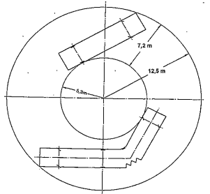
Figure 5 - Turning Capability
When the vehicle moves straight into the curved strip, no part of the vehicle shall protrude beyond the imaginary vertical plane touching the outer circle of the strip by more than 0.6 meters (see Figures 6a and 6b).
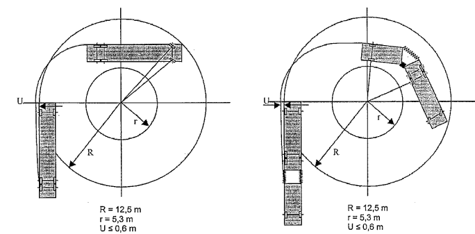
Figure 6a - Turning Capability of Single-Unit Vehicles
Figure 6b - Turning Capability of Articulated Vehicles
원본 문서(PDF)
관계도
문서를 클릭하면 열립니다. 빨간 테두리=효력을 변경하는 관계.
번역본
이 문서는 다음 언어로 제공됩니다: