
This Circular stipulates technical methods for collecting, processing data, and establishing surveying products from images taken by unmanned aerial vehicles (UAVs) for mapping work. It includes contents such as determining fixed station points, controlling images and inspections; collecting GNSS data on UAVs and original images; processing data and creating products such as point clouds, surface digital models, height digital models, and orthophoto maps. This Circular takes effect from August 16, 2021.
Scope of application
This Circular applies to organizations and individuals conducting mapping surveys using unmanned aerial vehicles (UAVs).
Key points
- Determination of fixed station points, image control and inspection
- Collection of GNSS data on UAVs and original images
- Data processing and creation of products from UAV images
- Inspection, packaging, and submission of mapping survey products.
- Effective date: August 16, 2021
🌐 Social impact of this document
- Improving the quality of surveying data and products from UAVs
- Saving time and costs in mapping surveys
- Developing new technology applications in the field of mapping surveys.
❓ Frequently asked questions
When does this Circular take effect?
This Circular takes effect from August 16, 2021.
What are the main contents of this Circular?
The main contents include determination of fixed station points, image control and inspection; collection of GNSS data on UAVs and original images; processing data and creation of products from UAV images.
Who does this Circular apply to?
This Circular applies to organizations and individuals conducting mapping surveys using unmanned aerial vehicles (UAVs).
Full text
|
MINISTRY OF NATURAL RESOURCES AND ENVIRONMENT |
SOCIALIST REPUBLIC OF VIET NAM |
|
Number: 07/2021/TT-BTNMT |
Hanoi, June 30, 2021 |
CIRCULAR
TECHNICAL REGULATIONS ON THE ACQUISITION AND PROCESSING OF DIGITAL IMAGE DATA FROM UNMANNED AIRCRAFT FOR THE CONSTRUCTION AND UPDATE OF NATIONAL GEOSPATIAL DATABASE AT SCALE 1:2,000, 1:5,000 AND THE CREATION OF TOPOGRAPHIC MAPS AT SCALE 1:500, 1:1,000
SERVING THE CONSTRUCTION AND UPDATE OF THE NATIONAL GEOSPATIAL DATABASE AT SCALE 1:2,000, 1:5,000 AND THE CREATION OF TOPOGRAPHIC MAPS AT SCALE 1:500, 1:1,000
AT RATIO 1:2,000, 1:5,000 AND THE ESTABLISHMENT OF TOPOGRAPHIC MAPS AT RATIO 1:500, 1:1,000
____________
On the basis of Law on Surveying and Mapping dated June 14, 2018;
Decree No. Decree No. 27/2019/ND-CP dated March 13, 2019 of the Government detailing some provisions of the Law on Surveying and Mapping;
Decree No. Decision No. 36/2017/NĐ-CP dated April 4, 2017 of the Government stipulating functions, tasks, powers, and organizational structure of the Ministry of Natural Resources and Environment;
Decree No. Decree No. 36/2008/ND-CP dated March 28, 2008 of the Government on the management of unmanned aircraft and ultra-light aircraft; Decree No. 79/2011/ND-CP dated September 5, 2011 of the Government amending and supplementing certain articles of Decree No. 36/2008/ND-CP dated March 28, 2008 of the Government on the management of unmanned aircraft and ultra-light aircraft and Decree No. 58/2010/ND-CP dated June 1, 2010 of the Government detailing and guiding the implementation of some provisions of the Law on Militia and Self-Defense Forces;
The Minister of Natural Resources and Environment promulgates this Circular on technical regulations on the structure model and content of the national geographic base database at scales of 1:10,000 and 1:25,000.
The Minister of Natural Resources and Environment promulgates this Circular prescribing technical regulations on the acquisition and processing of digital image data from unmanned aircraft serving the construction and update of the national geospatial database at scale 1:2,000, 1:5,000 and the establishment of topographic maps at scale 1:500, 1:1,000.
PART I
GENERAL PROVISIONS
Article 1. Scope of Regulation
This Circular prescribes technical requirements for the acquisition and processing of digital image data from unmanned aircraft serving the construction and update of the national geospatial database at scale 1:2,000, 1:5,000 and the establishment of topographic maps at scale 1:500, 1:1,000.
Article 2. Applicability
This Circular applies to agencies, organizations, and individuals involved in surveying and mapping activities and the construction and update of the national geospatial database, and the establishment of topographic maps using the method of acquiring and processing digital image data from unmanned aircraft.
Article 3. Definitions and Abbreviations
1. In this Circular, the following terms shall be understood as follows:
a) Flight area is the range that needs to be flown to acquire data from unmanned aircraft;
b) Sub-flight area is the smaller areas divided from the flight area to conduct flights to acquire data suitable for the capabilities of the equipment and other conditions;
c) Ground control station is the device used to control unmanned aircraft;
d) Fixed station is the station where GNSS receiving equipment is installed at a point with accurate coordinates and elevation, used to provide correction data for real-time kinematic solutions or data for post-processing kinematic solutions.
2. Abbreviations
a) DEM (Digital Elevation Model) is a digital height model representing the height of the terrain surface;
b) DSM (Digital Surface Model) is a digital surface model representing the height of the uppermost layer of the earth's surface viewed from above;
c) GNSS (Global Navigation Satellite System) is a global satellite navigation system;
d) GeoTIFF (Tagged Image File Format for GIS applications) is a geographic coordinate tagged image format;
đ) GSD (Ground Sample Distance) is the size of a pixel of an aerial photograph projected onto the ground or the sampling distance on the ground;
e) UAV (Unmanned Aerial Vehicle) is an unmanned aircraft.
Chapter II
TECHNICAL REGULATIONS
Section 1
Regulations on Unmanned Aircraft and Equipment Systems
Article 4. Regulations on UAVs
1. The use of UAVs must comply with the provisions of Decree No. 36/2008/ND-CP dated March 28, 2008 of the Government on the management of unmanned aircraft and ultra-light aircraft and Decree No. 79/2011/ND-CP dated September 5, 2011 of the Government amending and supplementing certain articles of Decree No. 36/2008/ND-CP dated March 28, 2008 of the Government on the management of unmanned aircraft and ultra-light aircraft and Decree No. 58/2010/ND-CP dated June 1, 2010 of the Government detailing and guiding the implementation of some provisions of the Law on Militia and Self-Defense Forces.
2. UAV equipment must meet the standards prescribed in Circular No. 35/2017/TT-BQP dated February 12, 2017 of the Minister of National Defense on the standards for airworthiness; standards, procedures for issuing licenses for design, production, repair, maintenance, testing of aircraft, aircraft engines, propellers, and equipment of unmanned aircraft and ultra-light aircraft; operation of unmanned aircraft and ultra-light aircraft and must satisfy the following requirements before being allowed to be used to acquire digital image data for the construction and update of the national geospatial database at scale 1:2,000, 1:5,000 and the creation of topographic maps at scale 1:500, 1:1,000:
a) Capable of flying in automatic and semi-automatic modes;
b) Weighing no more than 25.0 kg at takeoff;
c) Capable of withstanding wind speeds of at least 8 m/s.
3. Radio equipment accompanying UAVs must be registered for frequency according to the provisions of Circular No. 05/2015/TT-BTTTT dated March 23, 2015 of the Minister of Information and Communications detailing and guiding the procedures for issuing licenses for the use of radio frequencies; leasing, lending radio equipment; shared use of radio frequencies.
Article 5. Digital Cameras and GNSS Devices Mounted on UAVs
Digital cameras mounted on UAVs must be integrated with GNSS devices to determine orientation elements during the acquisition of digital image data, and must meet the following requirements:
1. Digital cameras mounted on UAVs:
a) Must have a fixed focal length during flight;
b) Must have a continuous automatic shooting mode;
c) Must capture natural RGB color images with a resolution of at least 20 megapixels.
2. GNSS devices mounted on UAVs must receive multi-frequency signals from satellite navigation systems, with a minimum signal reception frequency of 1 Hz to meet post-processing dynamic measurement solutions or real-time dynamic measurements.
Article 6. Ground Control Equipment and Data Processing Software
1. Ground control equipment with display screens must be capable of installing software with the following basic functions:
a) Designing automatic flight paths based on selecting different UAVs and cameras, with basic parameters such as flight zone boundaries, ground resolution, horizontal and vertical coverage of images, and other related parameters;
b) Controlling and displaying UAV operation parameters such as position, altitude, speed, direction, battery status; monitoring the operational status of the camera, GNSS, connection status between the control device and the UAV, and other related parameters.
2. Data processing software must be able to process input data including data received from UAVs and fixed station data; create products including point clouds, DSM, DEM, orthophotos.
Section 2
Technical Provisions for Products
Article 7. Mathematical Basis
1. Point cloud, DSM, DEM, and orthophoto products must be established according to the National Reference System and National Coordinate System VN-2000, projection zone, central meridian implementation as stipulated in Circular No. 973/2001/TT-TCĐC dated June 20, 2001, issued by the Land Administration Department guiding the application of the National Reference System and National Coordinate System VN-2000.
2. The elevation system used in constructing the digital elevation model is the current national elevation system.
Article 8. Provisions on Original Images and Flight Altitude
1. Provisions regarding original images include:
a) Image quality
Original images must have uniform contrast, brightness, sharpness, and object colors that ensure image quality for data processing, with clear visual distinction of objects on the image; image blur must not exceed 0.25 GSD;
b) Image coverage: the horizontal coverage of original images must be ensured between 60% and 80%, and vertical coverage must not be less than 70%;
c) The ground resolution of original images must not exceed the value specified corresponding to the map scale and the basic contour interval required to be established as shown in Table 1 below:
Table 1
|
Basic Contour Interval |
Ground Resolution of Original Images (m) |
|||
|
Map Scale Required to be Established |
||||
|
1:500 |
1:1.000 |
1:2.000 |
1:5.000 |
|
|
0.5 m |
0,04 |
0,04 |
||
|
1.0 m |
0,04 |
0,08 |
0,08 |
0,08 |
|
2.5 m |
0,08 |
0,15 |
0,15 |
|
|
5.0 m |
0,15 |
0,30 |
||
2. Flight Altitude
The flight altitude above ground level when taking photos is selected based on the ground resolution of the image, calculated using the formula:
Where:
f is the focal length of the camera lens (m);
S is the pixel size (m);
GSD is the ground resolution of the image (m).
Article 9. Provisions on products and data accuracy
The products after processing data include point clouds, DSM, DEM, and orthophoto maps, which are regulated as follows:
1. Point cloud, DSM, DEM products
a) Point cloud data shall be stored in LAS format;
b) DSM, DEM data shall have a square grid structure with grid size specified in Table 2 below:
Table 2
|
Mean height difference of basic contour interval (m) |
Grid size of DSM, DEM (m) |
|
0,5 |
0.5 x 0.5 |
|
1,0 |
1.0 x 1.0 |
|
2,5 |
2.5 x 2.5 |
|
5,0 |
5.0 x 5.0 |
c) DSM, DEM data shall be stored in raster (GeoTIFF-32 bit) format and ASCII format;
d) The scope of DSM, DEM data must be cut to overlap the flight area boundary by 1 cm according to the map scale required for establishment and must not contain empty data within the flight area;
đ) The root mean square error of DEM elevation shall not exceed the values specified in Table 3 below:
Table 3
|
Heightdifferenceof basic contour interval(m) |
Rootnumbermeansquare error of DEM elevation (m)differenceissuedIn cases where topographic maps are established with a mean height difference of 0.5 m, this only applies to areas with stable, flat, clear terrain, sparsely vegetated areas, and the root mean square error of DEM elevation shall not exceed 0.125 m; |
|
1,0 |
0,25 |
|
2,5 |
0,80 |
|
5,0 |
1,70 |
e) The limit error of DEM elevation shall not exceed twice the root mean square error. Deviations of test measurements shall not exceed the limit error, and the number of measured values within the range of (70% - 100%) of the limit error shall not exceed 10%;
g) Electronic total stations or GNSS devices shall be used to measure and verify DEM in the field. Points used for measurement stations are points belonging to the second level survey network or higher as prescribed in Circular No. 68/2015/TT-BTNMT dated December 22, 2015, issued by the Minister of Natural Resources and Environment regarding direct topographic survey techniques for establishing topographic maps and geographic base databases at scales of 1:500, 1:1,000, 1:2,000, and 1:5,000.
2. Orthophoto map products
a) Orthophoto map data shall have a GeoTIFF 24-bit format, with natural colors that are harmonious, not too bright or too dark, without glare, and without cloud cover;
b) The resolution of the orthophoto map is specified in Table 4 below:
Resolution of orthophoto map (m)
Table 4
|
Map Scale Required to be Established |
c) The positional error of image points on the orthophoto map compared to the nearest control point shall not exceed 0.4 mm according to the required map scale; |
|
1:500 |
0,05 |
|
1:1.000 |
0,10 |
|
1:2.000 |
0,20 |
|
1:5.000 |
0,30 |
d) The orthophoto map must extend 1 cm beyond the inner frame of the map sheet; if the orthophoto map does not cover the entire map sheet, it must extend 1 cm beyond the flight area boundary.
Provisions on data acquisition and processing
Section 3
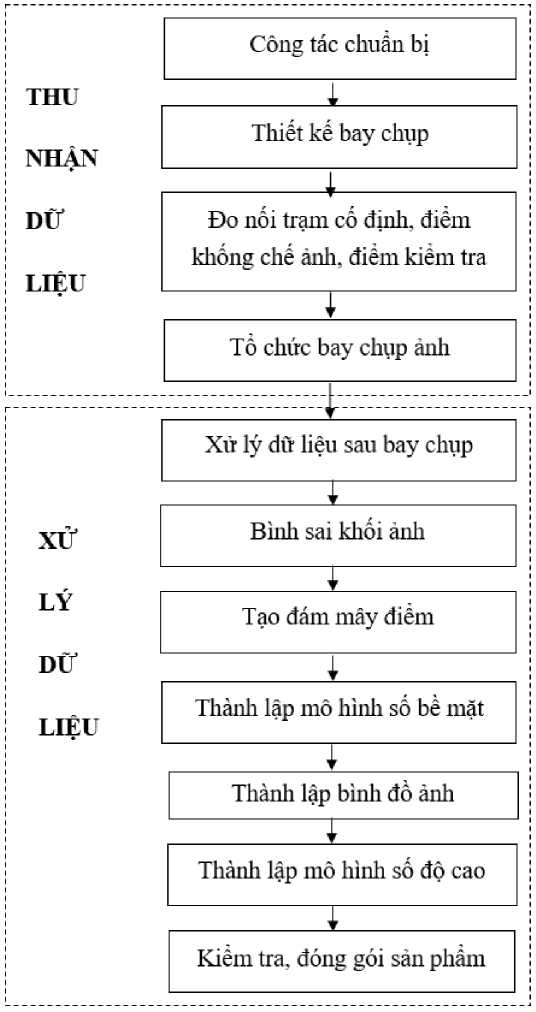
Article 10. Data acquisition and processing procedure
The data acquisition and processing procedure from UAVs includes the following steps as shown in the diagram below:
Article 11. Preparation work
1. Based on specific requirements for acquiring and processing digital aerial imagery data from unmanned aircraft systems for building and updating national geographic base databases at scales of 1:2,000 and 1:5,000, and establishing topographic maps at scales of 1:500 and 1:1,000, conduct surveys to prepare technical design and budget estimates and implement construction, including the following contents:
a) Survey the conditions of terrain, objects, and meteorology related to UAV flight photography and data processing. Survey and estimate the volume of surface terrain obscured by dense vegetation or structures whose heights cannot be determined using UAV aerial photography methods, with an area of 6 cm or more according to the required map scale, supplementary ground-based height surveying methods must be applied;
b) Select areas for UAV takeoff and landing that ensure safety, avoiding areas with significant aviation obstacles affecting takeoff and landing.2 2. Prepare application documents for flight permits in accordance with Decree No. 36/2008/NĐ-CP dated March 28, 2008, of the Government.
b) Selecting the area for takeoff and landing of the UAV must ensure safety and avoid areas with high obstacles that affect takeoff and landing.
2. Establishing the application file for flight permit issuance in accordance with the provisions of Decree No. 36/2008/NĐ-CP dated March 28, 2008 of the Government.
Article 12. Flight Design for Aerial Photography
1. Based on the scope, shape, and topographical characteristics of the flight area and the equipment of the UAV being used, determine the flight zones to ensure convenience for organizing flights and arranging fixed stations.
2. The design of UAV flight routes shall be carried out according to the principle of fully covering the flight area, ensuring accuracy and minimizing costs.
3. On the basis of the boundaries of the flight area, ground resolution of images, vertical and horizontal coverage of images, flight direction, camera photography parameters, and UAV technical specifications, determine the flight altitude and specific flight routes for each flight zone.
4. The aerial photography range of each flight zone must ensure that it extends beyond the boundary of the flight zone by at least the width of one flight route.
5. Select the flight direction based on the scope, shape, terrain conditions, and meteorological conditions of each flight zone to minimize flight time.
6. The flight route design product shall be presented on a suitable scale topographic map, including the following contents: flight zone boundaries, flight routes, coverage, and flight photography parameters.
Article 13. Measurement and Connection of Fixed Stations, Control Points, and Inspection Points
1. Arrangement and measurement connection of coordinates and elevations of fixed stations
a) Priority should be given to placing fixed stations at the center of the flight zone in locations with clear visibility and sufficient conditions to receive GNSS signals, not exceeding 10km from the boundary of the flight zone;
b) Fixed stations should be placed on existing markers or marked with wooden stakes or iron nails painted on-site and must remain intact throughout the construction and acceptance inspection period;
c) Coordinates and elevations of fixed stations shall be determined using electronic theodolite methods or GNSS technology with an accuracy equivalent to level 1 surveying network; the measurement and data processing procedures shall comply with the provisions of Circular No. 68/2015/TT-BTNMT. In cases where these methods do not meet the required elevation accuracy, the geometric leveling method must be applied to determine the elevation;
d) If the flight zone includes national satellite positioning stations, they may be used as fixed stations to serve the process of data collection during flights.
2. Arrangement and measurement connection of control points and inspection points
a) At least five planimetric and elevation control points must be arranged in each flight zone, prioritizing corners of the flight zone; for large flight zones, a minimum density of 1 point per 1km must be ensured; for linear-shaped flight zones, control points must not be aligned along both sides of the line, ensuring a minimum density of 1 point per 1km length;2; for linear-shaped flight zones, control points must be arranged to ensure a minimum density of 1 point per 3km length;
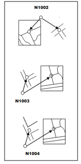
b) At least two planimetric and elevation inspection points must be arranged in each flight zone, evenly distributed within the zone and distant from control points; for complex-shaped flight zones, additional inspection points must be arranged at corners; for linear-shaped flight zones, the number of inspection points must ensure a minimum density of 1 point per 3km length;2 c) Control points and inspection points must be selected at distinct landmarks or objects with high contrast against surrounding surfaces such as intersections of linear objects or independent landmarks, traffic lane markings, etc. Selected objects must have a minimum width of 3 GSD, and if wider than 10 GSD, they must be chosen at corners (if clear) or at the intersection between the central line of the object and the boundary of another object. The location of control points and inspection points shall follow Model No. 01 attached as an appendix to this Circular;
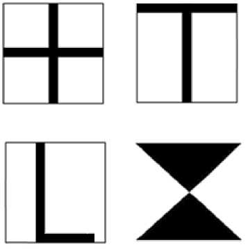
d) In cases where there are no distinct landmarks or objects in the flight zone, control points and inspection points must be marked with control targets before aerial photography. Control targets should be designed in the shapes of ┼, or T, L. Control targets must have a minimum width of 3 GSD and a minimum length of 5 GSD. The layout of control targets outside the site shall follow Model No. 02 attached as an appendix to this Circular;
e) Control points and inspection points must be marked with wooden stakes, iron nails, or painted marks on-site, ensuring their existence throughout the construction and acceptance inspection period; f) After determining the positions of control points and inspection points, sketches and photographs must be taken at the actual site to facilitate recognition during data processing. At each position of control points and inspection points, a minimum of four photos must be taken from the East, West, South, and North directions to ensure a comprehensive view of the surroundings;
g) Coordinates and elevations of control points and inspection points shall be determined using electronic theodolite methods or GNSS technology with an accuracy equivalent to level 2 surveying network; the measurement and data processing procedures shall comply with the provisions of Circular No. 68/2015/TT-BTNMT. In cases where these methods do not meet the required elevation accuracy, the geometric leveling method must be applied to determine the elevation.
e) After determining the position of the control point, the inspection point must draw a diagram and take photos on-site to easily recognize during data processing. At each location of the control points, the inspection point must take a minimum of 04 photos from the East, West, South, and North directions to ensure a comprehensive view of the surroundings.
g) The coordinates and elevation of the control points and inspection points shall be determined using electronic total station methods or GNSS technology with accuracy equivalent to the second-order survey network; the surveying and data processing procedures shall be carried out in accordance with Circular No. 68/2015/TT-BTNMT. In cases where these methods do not meet the requirements for height accuracy, geometric leveling methods must be applied to determine the height.
Article 14. Aerial Photography Operations
1. UAV Aerial Photography
a) Contact the local management authority according to the granted flight permit to register the use of UAVs; agree on the area, time, and altitude of flight as stipulated in the permit;
b) Conduct a pre-flight check of the UAV's operational status, camera, GNSS, ground control equipment, and other accompanying devices;
c) Carry out aerial photography strictly in accordance with the purpose, area, and time permitted for flight; monitor the operation of the UAV and equipment throughout the flight. In case of adverse weather conditions or unstable operation of data acquisition equipment during flight, stop the flight and return the UAV to its starting position;
d) After each flight, back up data onto computer storage devices and conduct preliminary data review and assessment.
2. GNSS Measurement at Fixed Stations
a) Use multi-frequency GNSS receivers to capture signals every second during the entire flight photography period;
b) Turn on the GNSS receiver at least five minutes before takeoff and turn it off five minutes after the UAV has landed;
c) Independently measure the antenna height of the GNSS receiver at fixed stations three times using a steel tape measure, reading to the millimeter at the start of the flight, mid-flight, and before the end of the flight.
Article 15. Post-Flight Data Processing
1. Backup original image data from the camera, GNSS measurement data from fixed stations, and GNSS reception data from the UAV;
2. Calculate and determine the center coordinates of the photograph and the orientation elements of the images from the GNSS measurement data of the fixed station and GNSS reception data from the UAV;
3. Check the quality of post-flight data
a) Review general flight photography conditions such as aircraft speed, wind level, shooting time compared to design, and GNSS reception data quality;
b) Check the overlap of images at the edges of flight zones compared to design, open areas, and missed areas;
c) Check vertical and horizontal coverage of the photographs compared to design; vertical and horizontal coverage of the photographs must not be less than 5% of the design;
d) Check the quality of the photographs, assess image quality through clarity, contrast, lighting conditions, sun shadows, cloud shadows; evaluate image quality in areas where control points and inspection points are arranged;
4. If the flight range or photograph quality does not meet requirements, supplementary flights must be conducted.
Article 16. Block Image Adjustment
1. Establish a working environment (create a project) for block image adjustment. Each block image is created from one or more flight zones. In each project, establish mathematical foundations, input original image data, center coordinates of the photograph, coordinates and heights of control points and inspection points, and camera parameters;
2. Block Image Adjustment:
a) Select and measure all control points and inspection points appearing on the images;
b) Proceed with linking and adjusting the block images. The linking and adjustment process must utilize the maximum number of images within the block;
3. Evaluate the Quality of Block Image Adjustment
After block image adjustment, errors in the internal orientation elements of the camera, errors at control points and inspection points must be checked and must satisfy the following requirements:
a) Errors in the internal orientation elements of the camera must be stable: coordinate errors of the main image point must not exceed half the pixel value, focal length error must not exceed 5%;
b) Mean square errors in the planimetric and height positions of the field control points after block image adjustment must not exceed 0.2 mm according to the map scale, and height errors must not exceed 1/5 of the mean height difference of the basic leveling route; limit errors must not exceed twice the mean square error;
c) The difference between coordinates and heights at inspection points after adjustment compared to field measurements must not exceed 0.3 mm according to the map scale in planimetry and 1/4 of the mean height difference of the basic leveling route in height.
Article 17. Creating Dense Point Clouds
1. When the block image result meets the requirements for error correction, proceed to create a dense point cloud from the calculated error-corrected block image results with a size not smaller than the resolution of the original image. Review and remove points with abnormally high values compared to the surrounding area.
2. In cases involving multiple block images, it is necessary to continue creating point cloud boundaries between adjacent block images. The boundary error must not exceed 0.3 mm according to the map scale on the plane and 1/4 of the basic contour interval regarding the height of the map to be established.
Article 18. Establishing Digital Surface Models
Use the point cloud to establish digital surface models for the flight area. Set the DSM grid size according to the map scale required as specified in Table 2 of this Circular. Edit and cut the digital surface model in a rectangular shape that extends 1 cm beyond the inner frame of the map section to be established.
Article 19. Establishing Image Orthomaps
1. Use the digital surface model and the original image to establish image orthomaps according to the block image with the image resolution specified in Table 4 of this Circular. The image orthomaps must ensure uniform tone and average contrast.
2. The accuracy of the image orthomaps at the positions of control points and field check points must meet the planimetric error requirements stipulated in point c, Clause 2, Article 9 of this Circular.
3. The boundary between adjacent block images on the image orthomaps must ensure a planimetric error not exceeding 0.5 mm according to the map scale required to be established.
4. Cut and divide the image orthomaps into rectangular shapes that extend 1 cm beyond the inner frame of the map section to be established.
Article 20. Establishing Digital Elevation Models
1. Establishing DEM includes the following tasks:
a) Using point cloud data and image orthomaps to classify and delineate terrain, objects, land cover, water surfaces, and determine areas requiring supplementary field survey elevation measurements due to inability to determine through UAV image acquisition methods with an area of 6 cm or more according to the required map scale;2 b) For areas requiring supplementary field survey elevation measurements, detailed topographic surveys shall be conducted in accordance with Circular No. 68/2015/TT-BTNMT;
c) Determine the ground surface, and filter out objects above the ground from the point cloud data;
d) Interpolate ground elevations in areas where objects have been filtered out using surrounding elevation points; create a preliminary DEM for the entire flight area;
đ) Use image orthomaps, DSM, digitized water data, and supplementary field survey elevation data to normalize and adjust the preliminary DEM; create a DEM for the entire flight area.
2. After normalization and establishment, the digital elevation model must undergo editing and cutting in a rectangular shape that extends 1 cm beyond the inner frame of the map section.
3. The DEM product, after establishment, must be inspected and evaluated for quality by the construction unit according to the following provisions:
a) Inspect and evaluate the accuracy and consistency between the DEM and the image orthomaps and classified, filtered point data, with a 100% inspection rate of all sections of the flight area;
b) Measure and evaluate the accuracy of the DEM's elevation at the site with a 3% inspection rate of all sections of the flight area.
b) Measuring and evaluating the accuracy of the DEM's height at the site with a sampling rate of 3% of the flight area's fragments.
Article 21. Inspection and Packaging of Products
1. The work of inspection, evaluation, and acceptance of product quality shall be carried out in accordance with Circular No. 24/2018/TT-BTNMT dated November 15, 2018, issued by the Minister of Natural Resources and Environment on inspection, evaluation, and acceptance of quality for surveying and mapping products. The content and level of inspection for DEM products shall be implemented according to Clause II.2.3 of Appendix 1a of Circular No. 24/2018/TT-BTNMT for DTM products.
2. Packaging of Products
a) DSM and DEM products shall be packaged with map sheets and metadata.
b) Orthophoto maps shall be packaged with map sheets, and other products shall be packaged by flight area.
a) Survey data of fixed station points, control photo points, and check points;
b) GNSS data from UAVs, original image data, results of coordinate center calculation, camera calibration parameters after orthorectification;
c) Point cloud data, surface digital model, height digital model, orthophoto maps;
d) Technical summary report;
e) Other products (if any) must be specifically defined in the technical design and budget approved by the competent authority.
Chapter III
IMPLEMENTING PROVISIONS
Article 22. Effectiveness
This Circular takes effect from August 16, 2021.
Article 23. Implementation Organization
1. Ministries, ministerial-level agencies, government agencies, provincial People's Committees under central cities, and relevant organizations and individuals are responsible for enforcing this Circular.
2. During implementation, if there are any difficulties, they should be promptly reported to the Ministry of Natural Resources and Environment for consideration and decision.
|
Place of Receipt: |
DEPUTY MINISTER Nguyen Thi Phuong Hoa |
ANNEX
(Issued together with Circular No. 07/2021/TT-BTNMT dated June 30, 2021, issued by the Minister of Natural Resources and Environment)
|
Form No. 01 |
Layout Diagram for Selection of Control Photo Points and Check Points |
|
Form No. 02 |
Shape of Control Mark Arranged in the Field |
Form No. 01. Layout Diagram for Selection of Control Photo Points and Check Points
Form No. 02. Shape of Control Mark Arranged in the Field
Original document (PDF)
Relations map
Click a document to open. A red border = a relation that changes validity.
Translations
This document is available in the following languages: