
This Circular details the surveying, designing, manufacturing, erection, and acceptance of people's suspension bridge projects in the field of transportation. It includes technical requirements for labor safety, material quality, structural components, construction products, as well as maintenance procedures and handover of the project to local authorities upon completion.
Scope of application
State management agencies in the field of transportation; organizations and individuals involved in the surveying, designing, manufacturing, erection, and acceptance of people's suspension bridge projects.
Key points
- Detailed regulations on the surveying and designing of people's suspension bridge construction projects
- Technical requirements for labor safety during construction
- Management of material quality, structural components, construction products, and equipment installation in the project
- Comparative testing, quality inspection of structural elements during construction
- Acceptance and handover of people's suspension bridge projects to local authorities
🌐 Social impact of this document
- Ensuring labor safety and quality of people's suspension bridge projects
- Supporting the management and effective operation of rural road bridges
- Improving travel conditions for people in rural areas
❓ Frequently asked questions
When does this Circular take effect?
This Circular takes effect from June 15, 2014.
Who is responsible for implementing this Circular?
The Director of the Ministry's Office, the Inspector General of the Ministry, Heads of Departments under the Ministry, the Director-General of the Vietnam Highway Administration, the Director of the Department of Construction Management and Quality Control of Transportation Projects, Heads of agencies and units under the Ministry of Transport, Directors of Provincial Departments of Transport, and related organizations and individuals are responsible for implementing this Circular.
Full text
CIRCULAR
Guidelines for the design, construction, and acceptance of pedestrian suspension bridges
____________
Pursuant to the Construction Law 2003;
Pursuant to Decree No. 15/2013/NĐ-CP dated February 6, 2013 of the Government on construction project quality management;
Pursuant to Decree No. 107/2012/NĐ-CP dated December 20, 2012 of the Government stipulating the functions, tasks, powers, and organizational structure of the Ministry of Transport;
At the proposal of the Director of the Department of Science and Technology and the Director General of the Vietnam Highway Corporation,
The Minister of Transport issues this Circular to guide the work of designing, constructing, and accepting pedestrian suspension bridges.
PART I
GENERAL PROVISIONS
Article 1. Scope of Regulation
This Circular guides the work of designing, constructing, and accepting pedestrian suspension bridges on rural roads.
Article 2. Applicability
This Circular applies to organizations and individuals directly involved or related to the activities of designing, constructing, and accepting pedestrian suspension bridges on rural roads.
Article 3. Explanation of Terms
1. Rural road includes main village roads, inter-village roads, intra-village roads, alleyways, and equivalent residential points, and main irrigation channels.
2. Pedestrian suspension bridge is a single-span suspension bridge with a width not exceeding 2.0 meters, located on rural roads; it is intended for pedestrians, livestock, horse-drawn carts, bicycles, motorcycles, motorized vehicles, and other rudimentary vehicles.
3. Main cable system consists of two main cables, each of which may consist of one or more bundles of steel wires manufactured according to the ASTM A603 Steel Strand Standard. The main cables are pulled from one anchorage over the tops of two towers to the opposite anchorage of the bridge.
4. Suspension cable system consists of cable or steel beam components distributed along the length of the bridge girder to connect the bridge girder to the main cables.
5. Cable accessories include details such as anchorages, cable clamps (cable saddles), cable protection layers, and other mechanical parts.
6. Anchorage system includes structures that support and anchor the main cables such as saddle anchors at the top of the tower, spreader anchors (diversion anchors), and tensioning devices (turnbuckles) at the anchorage.
7. Strand cable is a combination of high-strength parallel or twisted steel wires manufactured according to the ASTM A603 Standard, serving as the basic component for manufacturing main cables and suspension cables.
8. Anchorage is a large reinforced concrete and stone structure partially buried in the ground to create sufficient weight and passive resistance force to serve as an anchor counterweight to hold the main cables.
9. Bridge tower is a structure designed to support the main cables at the top of the tower. The bridge tower is constructed above the pier or abutment in the form of a steel or reinforced concrete (RC) portal frame.
10. Bridge width (B1) is the space between two curb rails (wood or steel) reserved for people and vehicles crossing the bridge, measured in meters.
11. Bridge width (B) is the distance between the centers of two suspension cables horizontally across the bridge at the point where they connect to the transverse girder, measured in meters.
12. Main cable sag (f) is the difference in height between the midpoint of the line connecting the tops of the two towers vertically and the height of the main cable at the midspan of the bridge, measured in meters.
13. Span length (L) is the distance between the centers of two towers vertically along the bridge, measured in meters.
14. Abbreviations
- MNCNLS Highest historical water level.
- MNTNLS Lowest historical water level.
Article 4. General requirements for the design of pedestrian suspension bridges
1. Pedestrian suspension bridges are classified into three types (Type I, II, III) based on traffic volume, as specified in Appendix I attached to this Circular. The main components of pedestrian suspension bridges include: main cables, bridge towers, piers (abutments), deck systems, anchorages, suspension cable systems (details in Figure 1 of Appendix II attached to this Circular).
2. The design life of pedestrian suspension bridges must be at least 25 years.
3. Pedestrian suspension bridges of Type I and Type II may allow rudimentary animal-drawn vehicles to pass through the bridge but only in one direction, one vehicle at a time, and must have warning signs to ensure visibility when entering and exiting the bridge.
When planning to construct pedestrian suspension bridges of Type I and Type II, comparative studies with cable-stayed bridges and rigid bridges should be conducted to select the most economical option, considering maintenance and repair costs during the design life of the bridge.
4. To provide data for the design of pedestrian suspension bridges, surveys must be carried out according to the provisions in Appendix III attached to this Circular and other relevant laws.
5. When designing structural components and foundations of pedestrian suspension bridges, general regulations of the 22TCN 272-05 Standard on limit state design theory, structural and foundation calculations, geological, hydraulic, and hydrological requirements, safety requirements for structures and means of transport must be followed. For the loadings of pedestrian suspension bridges, the provisions of Article 8 of this Circular shall apply.
6. For mechanical details made of steel including turnbuckles and accessories, connections between cables, cable-to-cable connections, and cable-to-steel beam or wooden component connections, the design requirements stipulated in Part 6 "Steel Structures" of the 22TCN 272-05 Standard must be adhered to. Other steel details must be designed and manufactured as specialized industrial products and must ensure a level of safety appropriate to the primary load-bearing parts of the bridge, referring to current standards on the design, fabrication, and acceptance of steel structures.
7. The anchorage system and steel or cable details for connecting the anchorage to the main load-bearing cables of the bridge must be designed with corrosion protection measures sufficient to ensure the design life of the bridge under normal maintenance conditions as prescribed in the Bridge Maintenance Procedures.
8. It is encouraged to apply typical designs of pedestrian suspension bridge spans approved by the Ministry of Transport to ensure the quality of span structure design and reduce project costs. The pier, column, and foundation structures are designed according to specific site conditions regarding terrain, geology, and hydrology.
9. Pedestrian suspension bridges with catenary shapes are suitable for good geological conditions, high riverbanks, and large floods during the flood season where building intermediate piers in rivers is difficult. In weak geological conditions and plain areas, the catenary suspension bridge layout must be compared with cable-stayed bridge layouts and other types of span structures to choose the best option.
10. Some general construction requirements
a) The longitudinal profile of the bridge deck (in the absence of live loads) has a convex curve shape;
b) The suspension cables supporting the bridge girder and deck vary in length to match the sag of the main cables along the length of the bridge girder;
c) Cable towers must be equipped with lateral braces to ensure stability. The two cable towers should be of equal height and have identical construction. They can be made of reinforced concrete or composite steel shapes, with or without pin connections at the base of the columns. In exceptional cases with valid economic and technical reasons, the two cable towers may have different heights;
11. A design dossier must be prepared in accordance with Appendix IV issued along with this Circular. The design dossier must be stored in accordance with the laws on recordkeeping;
Article 5. Selection of Location for Pedestrian Suspension Bridges
The selection of the bridge location is based on the following criteria:
1. Compatibility with the planning of village roads or existing paths for socio-economic development purposes, construction standards, topographical, geological, and hydrological conditions to determine a reasonable bridge plan, taking into account future traffic development, prioritizing safe traffic during rainy seasons and floods;
2. Prioritize locations where the river or stream course is straight, the riverbed or streambed is narrow, and the flow is parallel along both banks, with stable channels;
3. Prioritize bridge alignment perpendicular to the flow direction;
5. Bridges should not be placed near existing structures on both sides of the river such as ports, power transmission lines, hydraulic works. In unavoidable cases, the Project Owner must coordinate with relevant agencies to relocate less important structures;
6. Bridge locations should be selected based on the Minimum Navigation Channel Level (MNCNLS), avoiding areas prone to erosion or deposition. Avoid placing bridges too close to the confluence downstream or upstream. The MNCNLS is determined through actual surveys;
7. Foundation (abutment) locations should be chosen where there is no risk of landslides and no groundwater;
Chapter II
REQUIREMENTS FOR STRUCTURAL DESIGN
Article 6. General Principles
1. Comprehensive data collection must be conducted according to current standards, including topography, geology, climate, hydrology, live load requirements, and mechanical properties of materials before commencing design work;
2. Structures, prefabricated components (including mechanical parts such as tension devices, cable clamps, cable connection rings, or deck structure connections...), and foundations of pedestrian suspension bridges must be calculated according to the limit states specified in Standard 22TCN 272-05;
a) Strength Limit State: This state occurs due to loss of load-bearing capacity or non-use. Calculations aim to ensure the necessary strength and stability of the structure to prevent phenomena such as overall shape instability, positional instability (resistance to sliding, overturning, heaving...), uniform failure, new failures when the structure is subjected to repeated loads, and failures under simultaneous effects of forces and adverse environmental impacts (erosion...);
b) Serviceability Limit State: This state occurs when the structure cannot continue normal use. Calculations aim to prevent the formation of cracks in reinforced concrete structures or excessive and prolonged widening of existing cracks, and to prevent excessive displacements of structural components, particularly the towers and main girders (deflection, rotation, vibration);
c) Special limit states shall not be considered for pedestrian suspension bridges;
3. Dynamic wind effects on pedestrian suspension bridges must be calculated when the B/L ratio is less than 1/25;
4. Lateral vibration dampers must be installed for pedestrian suspension bridges when the B/L ratio is less than 1/25;
5. Depending on the calculated lateral stability requirements, lateral vibration dampers must be installed. In simple cases, lateral vibration dampers may consist of round steel bars with diameters ranging from 8 to 12 millimeters (d = 8-12 mm) placed below the deck structure and anchored at the tower bases. A better option is to install two symmetrical curved steel cables on both upstream and downstream sides of the bridge, connected to the ends of the transverse girders of the deck system. In this case, the lowest point (anchorage point) of the two dampers must be higher than the highest historical water level.
Article 7. Requirements for Materials and Components
1. The mechanical and physical properties of materials used in bridge components, including steel cables, must comply with the provisions set forth in Standard 22TCN 272-05.
2. For steel cables, they must also conform to Standard ASTM A603. Main cables must be steel core cables.
3. For mechanical parts such as winches, anchors, and cable clamps, they must comply with the provisions stipulated in Clause 6, Article 4 of this Circular.
Article 8. Loads and Effects
1. Classification of design loads and static load regulations shall be carried out according to Standard 22TCN 272-05.
2. Live Load of Simple Vehicles and People
a) For pedestrian suspension bridges, consider the uniformly distributed load on the bridge deck area as 3 kN/m2 (300 KG/m2), verified with a representative concentrated load for motorcycles (without impact consideration) at 5 kN (500 KG);
c) Wind Load: The static wind load is uniformly distributed and depends on the design wind speed of the bridge area. The design wind speed follows the provisions of Technical Regulation QCVN 02:2009/BXD corresponding to the region and terrain where the bridge is constructed;
Dynamic effects of wind on pedestrian suspension bridges must be considered as a separate aerodynamic problem for cable-stayed bridges;
d) Earth Pressure: Active and passive earth pressures must comply with Standard 22TCN 272-05;
đ) Handrail Load: Includes the self-weight of the handrail plus a uniformly distributed force along the bridge: vertically 0.5 kN/m; horizontally 1 kN/m;
e) Temperature Influence must comply with Standard 22TCN 272-05.
3. Load Combinations
Pedestrian suspension bridge structures shall be calculated based on the load combinations specified in Table 3.4.1-1 of Standard 22TCN 272-05 but only verify Limit State I, II, III, and Serviceability Limit State.
Article 9. Selection of Bridge Layout and General Arrangement
1. Apply a single-span layout with two towers positioned on piers (abutments) at stable river or stream banks without risk of erosion on both sides, as shown in Figure 2 of Appendix I issued together with this Circular.
2. To reduce sedimentation and bank erosion near the bridge, the positions of the two towers and piers (abutments) may be moved further inland. If hydrological and hydraulic conditions pose a risk of erosion before the pier (abutment) foundation, protective works sufficient to ensure stability should be arranged.
3. The ratio of main cable length (f) to span length (L) should be selected within the range f/L = 1/8 - 1/12.
5. The two angles of inclination of the main cable at the top of the tower towards the anchorage pier and the beam span should be chosen to be equal.
6. To increase the stability of the span structure, a layout connecting the main cable closely to the deck surface at midspan (without hangers there) may be applied.
7. The natural frequency of the span structure in vertical and horizontal directions must not coincide or be multiples of each other.
9. The underside of the beam must be higher than the minimum design water level by 1 meter (to prevent floating debris from impacting the beam during major floods).
Article 10. Structural Analysis
All methods of structural analysis specified in Standard 22TCN 272-05 may be applied to analyze the main span of a suspended pedestrian bridge. Calculations for the structural main span must be based on deformation diagrams. It is recommended to use finite element models and commercially available computer programs.
The structural analysis of a suspended pedestrian bridge is conducted for various construction and operational stages: completion state analysis of the bridge and analysis of structural states during construction and operation.
Article 11. Piers (abutments), Bridge Towers, and Accessories
1. Requirements for Pier (Abutment) and Bridge Tower Construction
a) Bridge towers are constructed on piers or abutments.
Piers (abutments) are made of reinforced concrete or stone masonry, with structural dimensions determined by calculations;
Bridge towers (bridge portals) consist of two tower columns and horizontal connections between them, materials can be steel or reinforced concrete.
b) Bridge towers support main cables and transmit forces from the main cables to the pier (abutment) structures and foundations.
Across the bridge, bridge towers are constructed in a portal frame form consisting of two tower columns and horizontal connections. The width of the tower column across the bridge is usually chosen equal to the height of the tower column.
Reinforced concrete bridge towers are typically rigidly connected at the base of the tower columns. The cross-section of the tower column can vary or remain constant and are solid sections. Main cables can pass over cable saddles with roller systems at the top of the tower.
Steel bridge towers are composed of steel shapes or steel bracing plates, using welded or riveted connections. Along the length of the bridge, the base of the tower columns can be rigidly or pivotally connected to the piers. If the base connection of the tower columns is pinned, then the main cables are fixed at the top of the bridge tower.
2. Design Requirements for Bridge Towers
Bridge towers and components arranged at the top or bottom of the tower columns (main cable saddles, main cable redirection saddles, tower column base pins, and other parts) are designed according to the provisions for reinforced concrete structures and steel structures in Standard 22TCN 272-05.
Cable positioning accessories such as saddles and cable redirection devices are considered mechanical parts and must be designed and manufactured according to current steel structure standards, corresponding to external forces and impacts, and forced displacements calculated from the general bridge and tower calculation diagram.
3. Requirements for Cable Saddle Construction
Both ends of the main cables are connected to anchoring systems and pass over the top of the tower through cable saddle structures. Depending on whether the bridge tower is a pinned or rigid column, the main cables are either firmly fixed on the cable saddle tightly connected to the top of the tower or lie on the roller saddle of the cable saddle at the top of the tower.
Cable saddles are provided with grooves to securely hold individual strands (for parallel main cables) or bundles (for bundled main cables). The curvature radius of the cable saddle is calculated so that excessive tensile stress (the sum of axial tensile stress along the main cable and tensile stress due to bending of the strand) does not occur in the main cable.
For parallel main cable construction, the suspension cable connection to the main cable is carried out through cable clamps, pins, and bolts. The cable clamp is angled to prevent localized failure of the tower at that point. For bundled main cable construction, the suspension cable connection to the main cable is carried out through cable bands, pins, or bolts.
Article 12. Anchorages and cable adjustment equipment
1. General Requirements
The main cable anchorage system consists of gravity anchor blocks made of reinforced concrete buried in the ground and steel components connecting these anchor blocks to the main cable, designed according to Standard 22TCN 272-05.
Depending on the terrain and geological conditions at the bridge abutment, deep rock excavation anchorages or submerged reinforced concrete anchor blocks can be designed.
It is necessary to design appropriate steel components to tension and adjust the main cable at the bridge abutment and safely connect the anchorage system to the main cable. Mechanical parts of the winches and connections between the cable and other components such as beams or suspension ropes must be designed to ensure safe load-bearing capacity according to Standard 22TCN 272-05.
Drawings for the above-mentioned steel components must clearly specify material requirements, mechanical and physical properties of the steel, processing methods, machining accuracy, and inspection and acceptance procedures.
2. Typical structures of the main cable anchorage system
Main cable anchoring into the ground using anchor blocks. Anchor blocks are large reinforced concrete and stone structures with sufficient weight to withstand lateral forces and uplift forces from the main cable and have relatively diverse configurations.
The anchorage system includes two parts: the socket and the anchor block, specifically:
a) Socket: uses reinforced concrete and stone weights to anchor the main cable. Calculations take into account the passive earth pressure before the socket and the friction at the bottom of the socket foundation and soil. Different values of active earth pressure and friction coefficients are taken based on compaction conditions and geological conditions at the foundation bottom. If the socket is underwater, buoyancy pressure of water must also be considered.
b) Anchor block: The gravity anchor block usually consists of round steel bars with diameters of 30-50mm and steel shapes, anchored in concrete.
Conditions must be created to easily inspect the external part of the anchor block when space is too narrow, avoiding high humidity conditions that often cause severe corrosion of the anchor block.
Article 13. Main cables and accessories
1. General requirements for main cables
a) Main cables and accessories are designed according to Standard 22TCN 272-05.
b) Measures must be taken to prevent corrosion of steel cables throughout the bridge's design life. If a direct connection scheme between the main cable and the deck system is used at mid-span positions, enhanced anti-corrosion measures for the main cable should be implemented there.
c) Main cables are made of bare or covered hard-core wire ropes.
d) Bundles of cables within the main cable system of pedestrian suspension bridges should be placed parallel to each other.
The safety factor of the main cable is set at 0.45 for limit state design calculations.
2. General requirements for main cable connection accessories
a) Connection accessories between the main cable and the anchorage system (including winches) are considered mechanical components, with designs ranging from simple to complex depending on specific design but must ensure accurate manufacturing and anti-corrosion solutions to ensure the bridge's design life.
b) Prohibition of manufacturing methods such as heat punching holes or other manual manufacturing methods.
Cable clamps installation and tightening must follow the bridge design drawings. Cable clamp specifications are provided in Appendix V issued together with this Circular.
Article 14. Suspension ropes and connection accessories
1. Suspension ropes can be made of round steel bars or wire ropes depending on the design. For Type III bridges, the simplest option may be round steel bars with diameters of 14-16mm.
2. Connection accessories at both ends of the suspension ropes are considered mechanical components, with designs ranging from simple to complex depending on the calculated design but must ensure accurate manufacturing and anti-corrosion solutions to ensure the bridge's design life.
Article 15. Bridge Deck System
1. The bridge deck system must be designed to facilitate water drainage, preventing water accumulation and soil buildup on the deck surface.
2. Components of the bridge superstructure must be made of steel beams or trusses, with the deck being made of steel, not reinforced concrete (RC) deck. The movable bearings of steel superstructures may be placed on piers or columns.
It is recommended to apply a fully steel bridge deck system (steel I-beams for longitudinal and transverse beams, steel sheet deck with anti-slip ribs). The horizontal slope of the deck surface should be set at 0%.
3. Longitudinal Beam System
a) The longitudinal beam system consists of two or more longitudinal beams (trusses) connected by transverse beams and suspended cables. Longitudinal beams may be made of steel sections;
b) The ratio between the height h of the beam and the span length L significantly affects the overall stiffness of the system;
c) A typical configuration of this type of deck includes: longitudinal beams using I or U-shaped steel sections placed on I or U-shaped transverse beams. Connections between longitudinal and transverse beams are made with bolts and plates.
4. Selection of Bridge Width
The width of the bridge should be chosen so that the ratio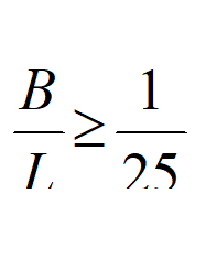 ensures stability against wind.
5. The deck is made of steel.
6. Guardrails, Expansion Joints
a) Guardrails can be made of wood or metal with a sturdy structure to withstand vertical and lateral loads. Guardrails must ensure sufficient safety closure to prevent people and children from falling through gaps;
b) Expansion joint gaps at the ends of beams should meet the requirements for expansion. Minimum width is 5 cm. The expansion joint structure must be wide enough to ensure convenience for inspection, repair, and cleaning.
Article 16. Foundation of Piers (Abutments) Supporting the Bridge Tower
1. The type of foundation and depth of the pier (abutment) foundation must be based on soil calculation and erosion conditions. Prioritize shallow foundations on natural ground to reduce construction costs.
2. The foundation design of the project follows the guidelines in Part 10 of Standard 22TCN 272-05 according to limit state theory.
3. Erosion Protection Measures for Pier (Abutment) Foundation Areas
a) When flow velocity v ranges from 1.5 m/s to 2.0 m/s and there is light wave action, reinforce the approach embankment slope with measures such as planting grass, paving with dry stone or mortared rubble, using concrete slabs anchored into the slope, or other suitable reinforcement methods.
b) When flow velocity exceeds 2.0 m/s, the embankment height is over 8.0 m, and the free height of the tower column body (from the bridge deck level to natural ground level) is greater than 4.0 m, then cement mortar grade 100 should be used to protect the approach embankment slope from erosion, and rock baskets should be installed along the edge of the pier foundation. Other erosion protection measures may also be applied.
Article 17. Connection Between Bridge and Road
The connection design between the bridge and road for rural suspension bridges must ensure smooth entry and exit for simple vehicles and adequate visibility.
Article 18. Design Requirements for Ancillary Works
1. Traffic Safety Facilities
On the approach road to the bridge, traffic signs and markers must be installed to guide and ensure traffic safety.
2. Signage Implementation
Follow the provisions of Circular No. 12/2014/TT-BGTVT dated April 29, 2014, issued by the Minister of Transport, guiding the management, operation, and exploitation of bridges on rural roads.
3. Waterway Marking
Chapter III
For navigable rivers, buoys and river markers must be placed according to Technical Regulation QCVN 39:2011/BGTVT.
Article 19. General Requirements
In addition to complying with the provisions from Article 20 to Article 26 of this Circular, construction work for people's suspension bridges must also comply with the Standards set forth in Appendix VI attached to this Circular and other current relevant Standards concerning bridge construction.
Article 20. Preparation Work
The preparation work for constructing people's suspension bridges shall be carried out like the preparation work for constructing general types of bridges and in accordance with the guidance provided in Standard TCCS 02:2010/TCĐBVN.
Article 21. Construction of Bridge Towers
1. Rectangular reinforced concrete bridge towers are constructed on-site using formwork made of wood or steel.
2. Steel bridge towers assembled from steel sections or steel plates connected by welding or riveting must be manufactured and quality-checked in workshops and installed at the construction site according to the provisions of Standard TCCS 02:2010 TCĐBVN.
Article 22. Construction of Bridge Piers and Anchors
1. Bridge piers are constructed similarly to the foundation and pier structures of general bridges.
2. The submerged part of the anchor is constructed like a general foundation in open excavation pits. For steel components and cables within the anchor, anti-corrosion measures must be taken into account.
Article 23. Main Cable Spreading and Tensioning
1. General Guidelines for Main Cable Spreading and Tensioning
a) Manufacturing Main Cables from Cable Coils
Main cable coils are manufactured in factories, imported, and delivered to the construction site in their original packaging as per design specifications. Steel strands used to manufacture main cable coils must comply with Standard 22TCN 272-05. After manufacturing, the main cable coils are stored, transported to the construction site, and erected into main cables. Each main cable bundle may consist of one or more cable coils depending on the specific design of each bridge.
The main cable coils are arranged parallel to each other (with positioning clamps spaced 2-3 meters apart) or bundled into a large cable bundle.
The length of each cable coil depends on the position of the main cable bundle. Each cable coil is marked at a minimum of five points: one point at the lowest point of the main cable in the middle span, two points at the saddle top of the tower, and two points at the anchorage location. The length of the cable coil and marking points must be determined in advance. When measuring, the length of the cable coil in its unloaded state is indirectly determined by measuring the length of the steel strand in its tensioned state with a minimum stress equivalent to the stress in the cable on the bridge in its unloaded state.
To pass the main cable across the river, guide ropes can be pulled over the top of the tower, or human power or boats, buoys can be used based on specific conditions and contractor technology.
b) Manufacturing Suspender Cables
If suspender cables are made from cable coils, they must be manufactured in factories according to design specifications. The manufacturing, inspection, and acceptance of suspender cables must comply with Standard ASTM A603.
If round steel bars with diameters of 14-16 mm are used, they can be manufactured in workshops or directly at the construction site according to design specifications.
c) Requirements for Main Cable Clamps (Main Cable Grips)
Main cable clamps are mechanical parts that must be manufactured in specialized machine shops with adequate conditions to ensure the quality of machining according to the design specifications.
During manufacturing, production technology must be established and tested, and all staff involved in production must be trained to fully understand technical requirements to ensure product quality.
All sharp corners must be rounded.
All main cable clamps must be inspected for defects using ultrasonic testing, labeled with clear identification numbers and shapes, and packed into units.
2. Installation of Cables
a) Installation of Main Cable Bundles
Before installing main cables from pre-manufactured parallel cable coils, thorough preparatory work such as erecting construction floor slabs, cable transport systems, cable pulling winches, guiding rail cars, horizontal lifting frames, etc., must be completed.
The sequence of installing cable coils within the main cable bundle must strictly follow the instructions in the design documentation. Each cable coil must be marked at a minimum of five positions, which are also specified in the design and must be closely monitored during installation.
b) Sequence for Pulling One Cable Coil
Before pulling one cable coil, the cable coil is brought to the anchorage position at one end of the bridge. A winch placed at the anchorage on the opposite side of the bridge is used to pull one end of the cable coil through the roller system on the bridge head and the pontoon on the river.
The cable coil must be positioned so that it is pulled along the longitudinal axis of the cable coil. When pulling the cable coils, a brake winch must be used at the cable coil reel to control and monitor the pulling process. Attention must be paid to reducing the pulling speed when the cable coil is about to be completely pulled off the drum to prevent accidents.
When the end of the cable coil reaches the opposite bank, before anchoring it at the anchorage, it must be temporarily secured by a holding system to prevent slipping.
Both ends of the cable coil at both ends of the bridge must be securely temporarily anchored, and should be promptly anchored at the anchorage.
c) Assembling Cable Coils into Main Cables
After the cable coils have been pulled and lie on the roller system of the construction floor slab, they must be inspected before being moved to the main cable bundle position and anchorage system. The cable coils must also be inspected and cleaned before being moved to the anchorage system.
When moving the cable coils horizontally from the rollers to the main cable bundle position and anchorage system, attention must be paid to only moving the cable coils after they have been lifted entirely off the rollers.
Before adjusting the geometric shape of the cable coils, the anchorage end of the cable coil must be pulled into the anchorage position and the tensioner installed.
To check the shape of the structure during construction, the contractor must calculate the geometric data at actual construction states with loads and impacts at those states, such as static loads, construction loads, temperature, and saddle displacement relative to the completed bridge state.
After all the cable coils in the main cable bundle have been installed in place, the main cable bundle must be tightly bound.
Protection of Main Cables: The bundling of the main cable bundle is carried out according to the specific design for each bridge.
3. Requirements for Adjusting the Sag of Main Cables
a) General Requirements
Sag adjustment can only be carried out when the temperature is stable.
When the main cable consists of multiple strands, one strand must be designated first as the standard strand. The absolute elevation calculation of the standard strand is determined corresponding to an ambient temperature and cable temperature of 25°C. At the time of measuring and adjusting sag, the absolute elevation of the standard strand will be recalculated based on the actual ambient temperature and cable temperature.
If the bridge has only one main strand, it shall be considered as the standard strand for adjustment;
b) Technical requirements for height when adjusting strand sag
The height difference between two standard strands at upstream and downstream is ±10 mm. For other strands (compared to the standard strand), the values will be -5 mm and +10 mm.
c) Installation of cable clamps (cable grips) and suspension cables
Before installing the cable clamp, the specific position of each clamp on the main cable bundle must be determined and marked with a number. The oil stains and dust on the surface of the main cable bundle must be cleaned, and they must be painted with anti-corrosion paint.
During transportation and installation, the cable clamps must be protected from damage.
The method of installing cable clamps will be detailed in the contractor's technological process based on the installation equipment and existing experience.
Once the cable clamp is accurately positioned on the main cable, tighten the clamp bolts. Tightening the bolts on the cable clamp will be carried out in three stages. Immediately after installing the cable clamp, proceed to thread the bolts and tighten the first stage of each bolt according to the specified tightening force in the design.
When hanging and installing the main beam, tighten the second stage bolts, and after completing the deck construction and protecting the cable, retighten all third-stage bolts to achieve the designed tightening force. To check the bolt force during tightening, the bolt-tightening device must have the function of converting torque into tensile force in the bolt.
4. Cable preservation work
a) Preservation work must be carefully carried out to ensure that the cable and accessories are not contaminated or damaged during transportation and installation;
b) After installation, the main cable must be thoroughly cleaned of dust, oil marks, and water on its surface and temporarily wrapped until it is officially wrapped and coated with anti-corrosion paint;
c) Coiling the main strands and suspension cables into rolls (spools) for transportation from the factory to the construction site must ensure that the steel wires and strands are not damaged.
Article 24. Construction of suspension cables
Suspension cables are usually placed on racks, then transported to the installation location using boats (floats). From the cable clamps, ropes can be lowered through the construction path to pull up the suspension cables, noting that the construction must be symmetrical.
Article 25. Construction of beams and deck system
The longitudinal beams, transverse beams, and deck panels are manufactured either in mechanical workshops or on-site according to the design drawings and regulations stipulated in Standard TCCS 02:2010/TCĐBVN.
The contractor may apply various solutions to assemble the deck beams with the suspension cables. It is encouraged to manufacture them in panels for convenient hoisting and installation.
Installation can start from both ends of the bridge moving towards the center span, or from the center span moving symmetrically towards both ends of the bridge.
Article 26. Construction of other project components and structures
1. Manufacturing and erection techniques for main cable saddles
Prior to manufacturing the main cable saddles, the contractor must thoroughly study the design documentation (including all specifications and related drawings) and prepare workshop drawings (manufacturing drawings) as well as establish technological processes for manufacturing and erecting these structures. Before mass production, the contractor must conduct trial manufacturing. The trial-manufactured products must be inspected and accepted for quality according to Articles 29 and 30 of this Circular.
2. Welding paths and quality inspection of welds
The contractor must prepare adequately and strictly adhere to welding technology and techniques. Welding operations must strictly comply with the provisions of Standard TCCS 02:2010/TCĐBVN as well as principles such as cleanliness at the welding site, heat input, and other conditions.
Ultrasonic testing of double-sided welds must be conducted.
3. Surface coating
The surface of the main cable saddle must be smooth and coated with a material to minimize friction and protect the main cable from damage.
4. Testing and trial assembly
a) When the main cable saddle base is completed in the workshop, a trial assembly must be conducted. Only after the product meets the design requirements and is approved by the supervising consultant can it be installed in the project;
b) The cable strand separators of the main cable saddle after welding must undergo double-sided welding treatment, followed by grinding to a smooth finish without burrs;
c) To install the cable strand separators accurately, their positions in the saddle cable grooves must be precisely determined and marked with paint;
d) During transportation and installation, the smooth surface of the main cable saddle must be protected from scratches, warping, or bending.
5. Installation of cable saddles
a) When installing the main cable saddle, attention must be paid to technical safety standards for lifting heavy objects.
b) When installing the main cable saddle, attention must be paid to the forward displacement of the saddle according to the construction installation sequence. During the installation of the rigid beams and deck, the main cable saddle is gradually adjusted to its designed position. The displacement of the main cable saddle must be continuously controlled and measured. Gradual adjustment of the main cable saddle to its designed position must be done so that under all circumstances, the lateral movement of the tower top remains within the allowable range of the design.
6. General requirements for labor safety
a) Units carrying out the manufacture and erection of components must fully comply with labor safety technical requirements as stipulated in Standard TCVN 8747:2012 and other relevant laws;
b) In each production area and work location, there must be a mandatory safety rule guide that everyone must follow;
c) In the production workshop, lighting and ventilation fans must be arranged to ensure industrial hygiene;
d) Cutting, welding, and painting work must not be carried out simultaneously in the same workshop or adjacent areas to avoid fire and explosion. Fire prevention and explosion protection measures must be implemented according to Standards TCVN 3254-86 and TCVN 3255-86;
đ) All workers must be equipped with full labor protection gear when working;
e) When working on the river, all workers must wear life jackets;
g) When the bridge is handling heavy loads, there must be a signal person coordinating smoothly;
h) There must be a dedicated department responsible for safety inspections.
i) In each construction team, there must be safety officers wearing red armbands who constantly remind everyone whenever there is a situation that may lead to safety risks during their shift.
k) Safety measures must be implemented when working at heights to prevent falls.
l) Safety measures must be taken in the arrangement of construction power networks.
m) Rescue equipment and devices must be available when constructing projects on rivers.
n) Construction and installation work shall not be carried out during the rainy and stormy season, and additional stability measures must be taken when wind speeds reach level 5 or higher.
Chapter IV
REQUIREMENTS FOR COMMISSIONING
Article 27. General Requirements
Quality management of people's cable-stayed bridge construction works must comply with the provisions stipulated in Decree No. 15/2013/NĐ-CP dated February 6, 2013, of the Government on quality management of construction works and Circular No. 10/2013/TT-BXD dated July 25, 2013, of the Minister of Construction detailing certain aspects of quality management of construction works.
Article 28. Commissioning of Survey and Design Works
1. The commissioning of survey works for people's cable-stayed bridges shall be carried out in accordance with the provisions of Article 12 of Circular No. 10/2013/TT-BXD.
2. The commissioning of design documents for people's cable-stayed bridges shall be carried out in accordance with the provisions of Article 15 of Circular No. 10/2013/TT-BXD.
Article 29. Management of Material, Components, Construction Products, and Equipment Quality
Materials, components, construction products, and equipment installed in people's cable-stayed bridge construction works must be subject to quality control in accordance with the provisions of Article 17 of Circular No. 10/2013/TT-BXD.
Article 30. Comparative Testing, Quality Inspection, and Load Testing of Structural Elements During Construction
Comparative testing, quality inspection, and load testing of structural elements during construction works shall be carried out in accordance with the provisions of Article 26 of Circular No. 10/2013/TT-BXD.
Article 31. Commissioning and Handover of Completed Works for Operation
1. The commissioning of construction works shall be carried out in accordance with the provisions of Article 20 of Circular No. 10/2013/TT-BXD.
2. The commissioning of construction phases or parts of construction works during the construction of people's cable-stayed bridges must be carried out in accordance with the provisions of Article 21 of Circular No. 10/2013/TT-BXD.
3. The final commissioning of completed people's cable-stayed bridges must be carried out in accordance with the provisions of Article 22 of Circular No. 10/2013/TT-BXD.
4. The establishment of maintenance procedures for bridges and the handover of people's cable-stayed bridges to local authorities shall be carried out in accordance with the provisions of Article 23 of Circular No. 10/2013/TT-BXD and Circular No. 12/2014/TT-BGTVT dated April 29, 2014, of the Minister of Transport guiding the management, operation, and exploitation of bridges on rural roads.
Chapter V
IMPLEMENTING PROVISIONS
Article 32. Effectiveness
This Circular takes effect from June 15, 2014.
Article 33. Implementation Organization
3. In the course of implementation, if there are any difficulties, organizations and individuals should report them to the Ministry of Transport for consideration and resolution.
Original document (PDF)
Download
Relations map
Click a document to open. A red border = a relation that changes validity.
Translations
This document is available in the following languages: