
This Circular stipulates technical procedures for creating groundwater resource maps at a scale of 1:100,000, including contents such as methods to represent aquifer layers, potential exploitable reserves and those already assessed, groundwater quality, groundwater research points, other symbols, and map section representation techniques.
Đối tượng áp dụng
This Circular applies to the creation of groundwater resource maps at a scale of 1:100,000 throughout the country.
Các điểm cốt lõi
- The map includes components such as aquifer layers, potential exploitable reserves and those already assessed, groundwater quality, groundwater research points, other symbols, and map sections.
- Specific representation methods for each component in the map are detailed in Appendix 1.
- Techniques for representing the content and form of the map are specified in Appendix 2.
- This Circular takes effect from August 5, 2013.
- The National Groundwater Resources Management Department is responsible for guiding and supervising the implementation of this Circular.
🌐 Tác động xã hội từ văn bản này
- To manage and exploit underground water resources reasonably
- To ensure the quality of underground water environment
- To support the planning of water resource utilization
❓ Câu hỏi thường gặp
When does this Circular take effect?
Circular No. 16/2013/TT-BTNMT on technical procedures for creating groundwater resource maps at a scale of 1:100,000 takes effect from August 5, 2013.
Who is responsible for guiding and supervising the implementation of this Circular?
The National Groundwater Resources Management Department is responsible for guiding and supervising the implementation of Circular No. 16/2013/TT-BTNMT on technical procedures for creating groundwater resource maps at a scale of 1:100,000.
What components are included in the groundwater resource map at a scale of 1:100,000?
The map includes components such as aquifer layers, potential exploitable reserves and those already assessed, groundwater quality, groundwater research points, other symbols, and map sections.
What contents are specified in Appendix 1 and Appendix 2 of this Circular?
Appendix 1 specifies specific representation methods for each component in the map. Appendix 2 specifies techniques for representing the content and form of the map.
Toàn văn
|
MINISTRY OF NATURAL RESOURCES AND ENVIRONMENTAND RURAL DEVELOPMENT __________ Number: 16/2013/TT-BTNMT |
SOCIALIST REPUBLIC OF VIET NAM Independence - Freedom - Happiness ______________ Hanoi, June 21, 2013 |
CIRCULAR
Technical regulations for the creation of underground water resource maps at a scale of 1:100,000
Pursuant to the Law on Water Resources No. 17/2012/QH13 dated June 21, 2012;
Pursuant to Decree No. 21/2013/NĐ-CP dated March 4, 2013, promulgated by the Government, stipulating the functions, tasks, powers, and organizational structure of the Ministry of Natural Resources and Environment;
Pursuant to Decree No. 24/2009/NĐ-CP dated March 5, 2009 of the Government detailing and providing implementation measures for the Law on Legislative Regulatory Documents;
Considering the proposal of the Director of the Water Resources Management Department, the Director of the Center for Water Resources Planning and Investigation, the Heads of the Science and Technology Department and the Legal Affairs Department;
The Minister of Natural Resources and Environment promulgates this Circular on technical regulations for the creation of underground water resource maps at a scale of 1:100,000,
PART I
GENERAL PROVISIONS
Article 1. Scope of Regulation and Applicability
Article 1. This Circular stipulates the contents, formats, and products of underground water resource maps at a scale of 1:100,000 for projects, programs, and tasks related to the investigation and assessment of underground water resources.
Article 2. This Circular applies to state management agencies for water resources, organizations, and individuals responsible for creating underground water resource maps at a scale of 1:100,000.
Article 2. Purpose of Creating Underground Water Resource Maps at a Scale of 1:100,000
Point 1. To present the results of the investigation and assessment of underground water resources at a scale of 1:100,000 or at a larger scale.
Point 2. To serve state management of underground water resources within key economic regions and inter-provincial river basins (inter-provincial river basins are defined according to Decision No. 1989/QĐ-TTg dated November 1, 2010 of the Prime Minister regarding the list of inter-provincial river basins), and socio-economic development planning at provincial and centrally-administered city levels.
Point 3. To provide a basis for the planning of underground water resources within key economic regions and inter-provincial river basins, and socio-economic development planning at provincial and centrally-administered city levels.
Point 4. To meet the needs of information extraction for relevant sectors, localities, organizations, and individuals involved in groundwater exploitation and utilization activities.
Article 3. Base Maps in the Creation of Underground Water Resource Maps at a Scale of 1:100,000
Point 1. Underground water resource maps at a scale of 1:100,000 are created based on topographic base maps and hydrogeological base maps at the same scale or a larger scale.
Point 2. The topographic base map is a topographic map at a scale of 1:100,000 (VN 2000 coordinate system) or a larger scale, compiled at a scale of 1:100,000 by the Ministry of Natural Resources and Environment.
Point 3. The hydrogeological base map is a hydrogeological map at a scale of 1:100,000 or a larger scale, compiled at a scale of 1:100,000. Hydrogeological maps are the basis for determining the distribution area, water storage capacity, chemical composition, and exploitation potential of underground water sources, as well as stratigraphic intervals and aquifer structures.
Point 4. In cases where there are no existing hydrogeological maps in the areas where the maps are being created, it is necessary to conduct surveys and draw up hydrogeological maps with sufficient information to support the creation of underground water resource maps.
Article 4. Technical Inspection and Product Acceptance Work
Technical inspection work and product acceptance shall be carried out in accordance with the current regulations of the Ministry of Natural Resources and Environment.
Article 5. Types of Products
Point 1. Products of underground water resource maps at a scale of 1:100,000 include:
Subpoint a) Underground water resource maps;
Subpoint b) Specialized maps:
- Actual condition maps of underground water resources;
- Quality maps of underground water;
- Groundwater flow modulus maps.
Subpoint c) Explanatory notes for underground water resource maps;
Subpoint d) Appendices: summary tables and statistics of comprehensive and detailed investigation results according to aquifer structures and administrative units; lists of detailed investigation points and other information. Cross-section drawings and other diagrams.
Point 2. Underground water resource maps at a scale of 1:100,000 are published in paper and digital formats.
Article 6. Mathematical Basis for the Underground Water Resources Map at Scale 1:100,000
1. The underground water resources map at scale 1:100,000 is established in the National Geodetic Reference System and Coordinate System VN 2000 (UTM Grid, WGS84 Ellipsoid, Zone 6, distortion factor k).0 = 0,9996).
2. The central meridian of the underground water resources map at scale 1:100,000 is determined according to Table 1.
Table 1. Central Meridians According to Projection Zones
|
Serial number |
Left Meridian |
Axis Meridian |
Right Meridian |
|
Zone 48 |
102° |
105° |
108° |
|
Zone 49 |
108° |
111° |
114° |
|
Zone 50 |
114° |
117° |
120° |
3. The map frame, grid lines of longitude and latitude of the underground water resources map at scale 1:100,000 shall display both systems of longitude and latitude grids and kilometer grids, and comply with the current regulations for topographic maps of equivalent scale.
Chapter II
CONTENTS OF THE UNDERGROUND WATER RESOURCES MAP AT SCALE 1:100,000
Article 7. Base elements
1. Topographic base elements
On the underground water resources map at scale 1:100,000, the following terrain elements must be ensured to be displayed:
a) Mathematical basis layer: map name, grid frame, and elements outside the frame;
b) Topography layer: contour lines, elevation points, and elevation values;
c) Hydrographic layer: rivers, streams, lakes, and their names;
d) Transportation layer: roads, railways, bridges, and their names;
đ) Settlement layer: concentrated residential areas, clusters of residences;
e) Administrative layer: headquarters of district and provincial People's Committees, administrative unit names;
g) Boundary layer: district, provincial boundaries, border lines.
Detailed terrain elements must comply with the provisions of geographic information standards issued by the Ministry of Natural Resources and Environment. Terrain base elements may be reduced by 15 to 25% to ensure priority in displaying water resource elements.
2. Base geological hydrological elements
The base geological hydrological elements displayed on the underground water resources map at scale 1:100,000 include:
a) Distribution areas of water-bearing and non-water-bearing objects, including water-bearing structures, rock formations containing water, or large aquifer complexes, and structures, formations, complexes that do not contain water;
b) Water-bearing faults, predicted water-bearing faults, and faults with undetermined water-bearing conditions;
c) Quality of underground water.
Article 8. Special Elements
1. Distribution area, including water-bearing and non-water-bearing objects.
2. Underground water storage volume, including:
a) Potential exploitable underground water storage volume;
b) Exploited underground water storage volume that has been evaluated.
3. Underground water quality, including:
a) Major ions;
b) Salinity boundary of aquifers;
c) Trace element indicators;
d) Nitrogen indicators.
Chapter III
TECHNIQUES FOR DISPLAYING THE UNDERGROUND WATER RESOURCES MAP AT SCALE 1:100,000 DƯỚI ĐẤT TỶ LỆ 1:100.000
Article 9. Format of the Underground Water Resources Map at Scale 1:100,000
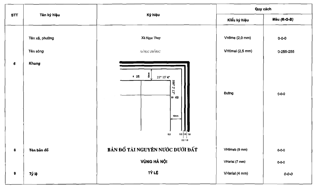
1. The map name and frame are displayed according to the provisions in the attached appendix to this Circular.
2. If the map consists of multiple pieces, a corner piece assembly diagram should be shown on the right side of the map frame.
3. The map legend is placed on the right side of the map, cross-sections are placed below the map. Where possible, the legend and cross-sections can be placed within the frame at appropriate positions.
Article 10. Techniques for Displaying the Contents of the Underground Water Resources Map at Scale 1:100,000
1. Principles of Display
The underground water resources map at scale 1:100,000 must display the results of research conducted during the investigation and assessment of underground water resources at scale 1:100,000. The contents and information displayed on the underground water resources map at scale 1:100,000 are based on the following principles:
a) Water-bearing and non-water-bearing objects are displayed according to distribution boundaries;
b) Potential exploitable volumes are displayed as regions;
c) Evaluated underground water storage volumes are displayed through approved storage levels, indicated by frames and storage values of each level;
d) Underground water quality is displayed as lines and points;
đ) Artificial structures such as hydrological stations, drilled wells, dug wells, and exposed underground water sources are displayed as points;
e) Faults on the underground water resources map at scale 1:100,000 are displayed as water-bearing, predicted water-bearing, and undetermined water-bearing conditions faults, shown by red lines, bold strokes.
2. Size of Objects to Be Displayed
On the underground water resources map at scale 1:100,000, objects displayed as regions must have actual sizes greater than or equal to 1 km2; objects displayed as lines must have actual lengths greater than or equal to 1,000 meters; on cross-sections, objects must have actual thicknesses greater than or equal to 10 meters, extending a minimum of 1,000 meters.
3. Techniques for Displaying the Map
a) Water-bearing structures, rock formations containing water, or large aquifer complexes, and structures, formations, complexes that do not contain water:
- Each water-bearing structure, formation, complex is displayed with information on its existence form, complex name, and distribution area;
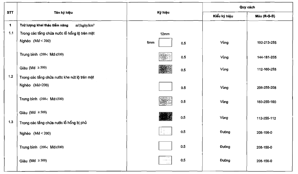
- Boundaries of complexes and surface aquifer layers are displayed by continuous purple lines, 0.4 mm thick; for covered complexes and aquifer layers, continuous purple lines, 0.4 mm thick, with arrows pointing towards the distributed complex or layer;
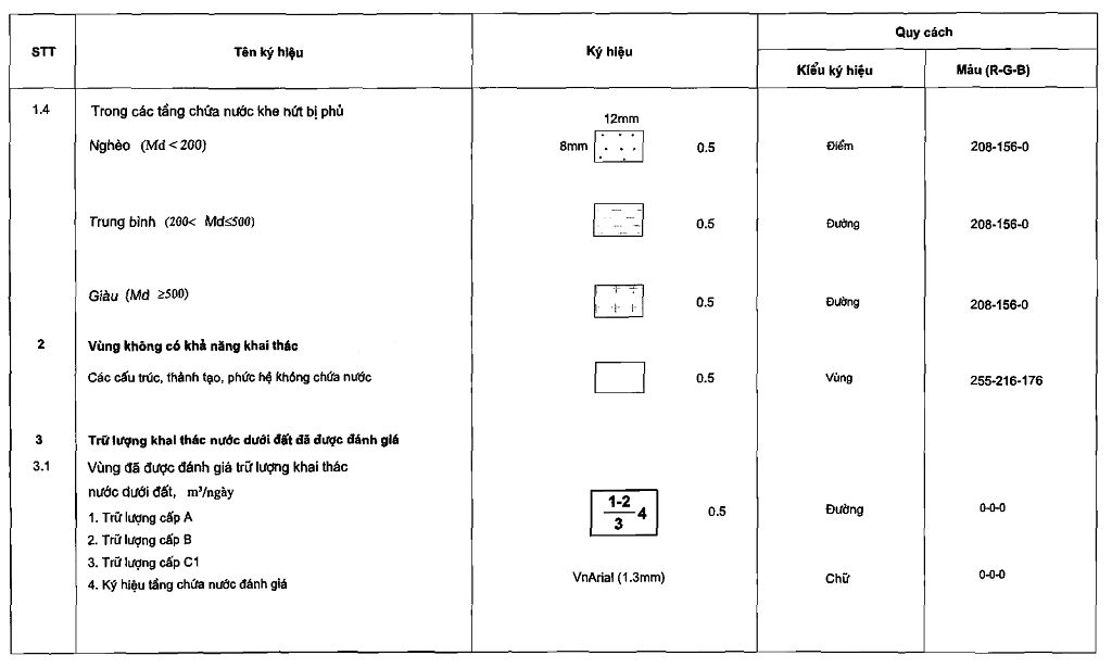
- Non-water-bearing structures, formations, complexes are displayed as brown regions.
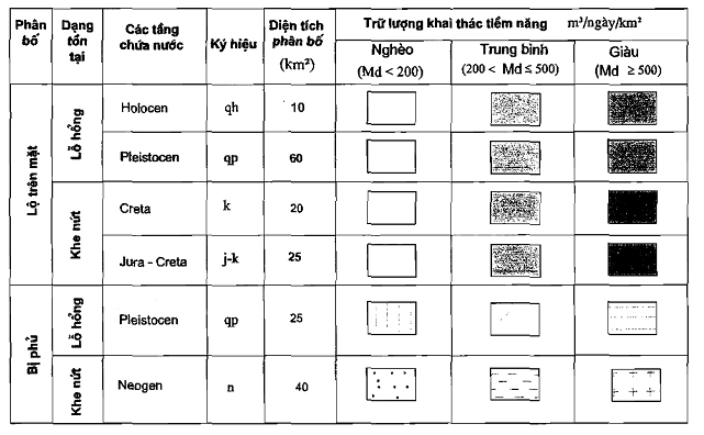
b) Potential exploitable volumes classified as poor, medium, and rich are displayed by varying shades of color;
- For exposed surface porous aquifers, they are displayed as blue regions;
- For exposed surface fissured aquifers, they are displayed in green;
- For covered aquifers, they are displayed by brown lines, 1 mm thick, spaced 3 mm apart.
c) Evaluated underground water storage volumes are displayed using black frames, 1 mm thick, and black numbers and letters indicating storage values at each level, and symbols representing evaluated water-bearing units;
d) Underground water quality:
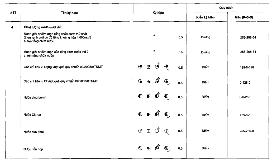
- Major ions are displayed at water points in blue for bicarbonate water, red for chloride water, and yellow for sulfate water;
- Salinity boundaries of aquifers are displayed by orange dashed lines, 0.5 mm thick, with arrows pointing towards higher total mineralization;
- Trace element indicators are displayed in purple when exceeding the National Technical Regulation on Groundwater Quality (QCVN 09/2008/BTNMT);
- Nitrogen indicators are displayed in light green when exceeding QCVN 09/2008/BTNMT.
đ) Research points for underground water:
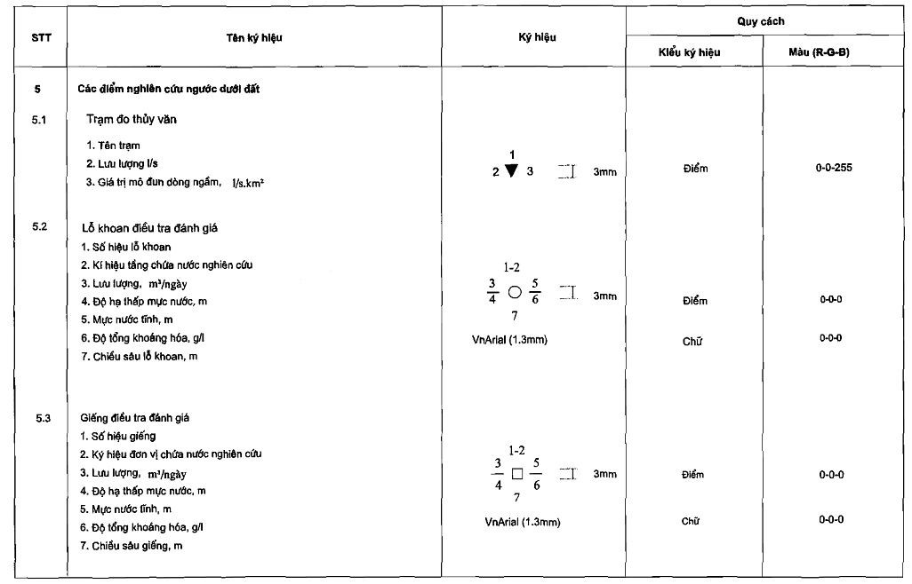
- Hydrometric station: represented by a downward-pointing blue triangle with a height of 3mm, accompanied by information such as the station name, flow rate, and value of the underground flow modulus;
- Drilling hole: represented by a black circle with a diameter of 3mm, accompanied by information such as the drilling hole number, symbol of the water-bearing unit under study, flow rate, water level depression, static water level, total mineralization degree, and drilling depth;
- Excavated well: represented by a black square with a side length of 3mm, accompanied by information such as the well number, symbol of the water-bearing unit under study, static water level, flow rate, water level depression, total mineralization degree, and well depth;
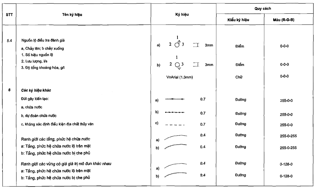
- Outcrop source: represented by a black circle with a diameter of 3mm and an arrow pointing upwards for outcrops flowing up and downwards for outcrops flowing down, accompanied by information such as the outcrop source number, flow rate, and total mineralization degree;
e) Faults are shown by red lines with a thickness of 0.7mm. Water-bearing faults are shown by continuous lines with a multiplication sign (x), predicted water-bearing faults by dashed lines with dots (.), and faults with undetermined water-bearing conditions by dashed lines;
g) The cross-section of the groundwater resource map shows the water-bearing units under study according to depth. The cross-section line must be drawn on the map in black with a thickness of 0.7mm. Each aquifer layer displays information on storage volume and water quality. Additionally, it shows the location and information of typical research facilities;
Specific methods and representation standards are detailed in Appendices 1 and 2 attached hereto;
Chapter IV
IMPLEMENTING PROVISIONS
Article 11. Implementation Organization
1. The Minister, Heads of Ministries equivalent to Ministries, agencies under the Government, Chairpersons of People's Committees of provinces and centrally governed cities, Director of the National Water Resources Management Agency, Director of the Center for Water Resources Planning and Survey, Heads of subordinate units of the Ministry, and related organizations and individuals are responsible for implementing this Circular;
2. The National Water Resources Management Agency is responsible for guiding and supervising the implementation of this Circular.
Article 12. Effective Date
1. This Circular takes effect from August 5, 2013;
2. During the implementation process, if there are any difficulties, please promptly report them to the Ministry of Natural Resources and Environment for study and amendment./.
|
DEPUTY MINISTER Nguyen Thai Lai |
ANNEX TO THE CIRCULAR
TECHNICAL REGULATIONS FOR DRAWING GROUNDWATER RESOURCES MAPS AT SCALE 1:100,000
(Issued together with Circular No. 16/2013/TT-BTNMT dated June 21, 2013 of the Minister of Natural Resources and Environment);
Appendix 01
GUIDELINES
GROUNDWATER RESOURCES MAP AT SCALE 1:100,000
(Issued together with Circular No. 16/2013/TT-BTNMT dated June 21, 2013 of the Minister of Natural Resources and Environment);
1. AQUIFER AND POTENTIAL EXPLOITABLE STORAGE VOLUME
2. AREAS WITHOUT EXPLOITABLE CAPACITY
 |
Structures, formations, and complexes that do not contain water (Q13vp; T1bv,...) |
3. EVALUATED EXPLOITABLE GROUNDWATER STORAGE VOLUME
 |
Areas where exploitable groundwater storage volume has been evaluated, m3t 06 of the annex issued together with this Circular. 1. Class A Storage Volume 2. Class B Storage Volume 3. Class C1 Storage Volume 4. Symbols for Evaluated Aquifers |
4. GROUNDWATER QUALITY
|
|
Boundary of salinity intrusion in the first aquifer (according to the boundary with total mineralization of 1,000 mg/l) a: Name of the aquifer |
|
|
Boundary of salinity intrusion in the second aquifer a: Name of the aquifer |
 |
Trace elements exceeding standard 09/2008/BTNMT |
 |
Nitrogen levels exceeding standard 09/2008/BTNMT |
 |
Bicarbonate water |
 |
Chloride water |
 |
Sulfate water |
 |
Mixed water |


5. GROUNDWATER RESEARCH POINTS
 |
Hydrometric station 1. Station name 2. Flow rate, l/s 3. Value of the underground flow modulus, l/s.km2 |
 |
Research and evaluation drilling wells 1. Drilling well number 2. Symbol of the water-bearing unit under study 3. Flow rate, m3t 06 of the annex issued together with this Circular. 4. Water level depression, m 5. Static water level, m 6. Total mineralization degree, g/l 7. Drilling depth, m |
 |
Research and evaluation excavation wells 1. Well number 2. Symbol of the water-bearing unit under study 3. Flow rate, m3t 06 of the annex issued together with this Circular. 4. Water level depression, m 5. Static water level, m 6. Total mineralization degree, g/l 7. Well depth, m |
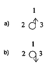 |
Research and evaluation outcrop sources a: Upward flow; b: Downward flow 1. Outcrop source number 2. Flow rate, l/s 3. Total mineralization degree, g/l |
6. OTHER SYMBOLS
 |
Tectonic faults: a: Contain water b: Predicted to contain water c: Undetermined water-bearing conditions |
 |
Boundaries of layers and complexes containing water a: Layers and complexes containing water exposed at the surface b: Layers and complexes containing water covered |
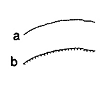 |
Boundaries of areas with different modulus values a: Layers and complexes containing water exposed at the surface b: Layers and complexes containing water covered |
 |
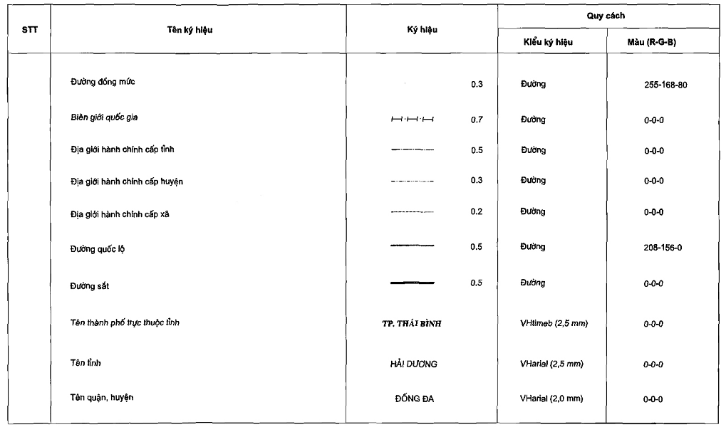
Contour lines |
 |
Elevation point, m |
 |
People's Committees and specialized agencies under them |
 |
Provincial administrative boundaries |
 |
District administrative boundaries |
 |
Commune administrative boundaries |
 |
National highways |
 |
Railway |
|
THÁI BÌNH CITY |
Name of city directly under province |
|
HẢI DƯƠNG PROVINCE |
Province name |
|
ĐỐNG ĐA DISTRICT |
Name of district, county |
|
NGỌC THỤY COMMUNE |
Name of commune, ward |
|
RED RIVER |
River name |
7. SYMBOLS ON THE CROSS-SECTION
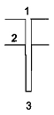 |
1. Drilling well number 2. Depth of layers, m 3. Drilling depth, m |
Appendix 02
TECHNICAL REGULATIONS FOR CONTENT AND FORM OF GROUNDWATER RESOURCES MAPSDƯỚI ĐẤT TỶ LỆ 1:100.000
(Issued together with Circular No. 16/2013/TT-BTNMT dated June 21, 2013 of the Minister of Natural Resources and Environment)
Văn bản gốc (PDF)
Tải văn bản
Bản đồ quan hệ
Bấm vào một văn bản để mở. Viền đỏ = quan hệ làm thay đổi hiệu lực.