
Circular No. 24/2010/TT-BTNMT stipulates surveying and creating seabed topography maps using multi-beam echo sounders, applicable to state management agencies for seas and islands, organizations, and individuals operating in this field. This circular guides technical methods, technological procedures, requirements for surveying, data processing, map editing, inspection, and product acceptance.
Đối tượng áp dụng
State management agencies for seas and islands, organizations, and individuals engaged in surveying and creating seabed topography maps using multi-beam echo sounders.
Các điểm cốt lõi
- Equipment used must be compatible, meet accuracy requirements, and be tested and inspected according to regulations (Article 2).
- Prior to construction, relevant materials must be collected, and a technical design estimate prepared for the survey area; work can only commence when testing and calibration results meet requirements (Article 2).
- Surveying procedures include preparation, technical design, installation, testing, construction, data processing, map editing, inspection, and product acceptance (Chapter I).
- Map accuracy requirements are based on Technical Regulations for Creating Seabed Topography Maps at a Scale of 1:50,000 and Mathematical Basis, Content Accuracy, and Symbol Requirements for Seabed Topography Maps (Article 4).
- Testing of multi-beam echo sounders is conducted for the central beam; software settings must comply with project technical requirements (Article 12).
🌐 Tác động xã hội từ văn bản này
- Positive impact: Time and cost savings during the surveying process, ensuring high accuracy for seabed topography maps.
- Negative impact: High technical requirements may pose difficulties for small organizations or those newly entering this field (equipment costs, manpower).
❓ Câu hỏi thường gặp
What requirements must equipment used meet?
Equipment used must be compatible and meet map accuracy requirements. Test documentation for machines and technical equipment must be stored alongside original maps (Article 2).
What preparations are needed before construction?
Before construction, relevant materials must be collected, and a technical design estimate prepared for the survey area. Construction can only proceed once all testing and calibration results meet requirements (Article 2).
How are map accuracy requirements defined?
Map accuracy requirements are based on Technical Regulations for Creating Seabed Topography Maps at a Scale of 1:50,000 and Mathematical Basis, Content Accuracy, and Symbol Requirements for Seabed Topography Maps (Article 4).
How is testing of multi-beam echo sounders conducted?
Testing of multi-beam echo sounders is conducted for the central beam. The testing process follows these steps: use a speed-of-sound meter, lower a test disk to the minimum depth, measure the depth of the test disk using the echo sounder (50 Fix with a 5-second interval between each fix), calculate system deviation, and enter correction numbers into the echo sounder. After testing, a report of the testing results must be compiled (Article 12).
What does the submitted product include?
Submitted products include: Testing and calibration results; Technical summary report; Digital seabed topography depth model; Seabed topography map (Article 24).
Toàn văn
|
MINISTRY OF NATURAL RESOURCES AND ENVIRONMENT ENVIRONMENT |
SOCIALIST REPUBLIC OF VIET NAM |
|
Number: 24/2010/TT-BTNMT |
Hanoi, October 27, 2010 |
CIRCULAR
Regulations on surveying and mapping seabed topography using multi-beam echo sounders
bằng thiết bị đo độ sâu sử dụng hồi âm đa tia;
MINISTER OF NATURAL RESOURCES AND ENVIRONMENT
BASED ON THE LAW ON ENACTMENT OF LEGAL DOCUMENTS;
Pursuant to Decree No. 25/2008/NĐ-CP dated March 4, 2008 of the Government stipulating the functions, tasks, powers, and organizational structure of the Ministry of Natural Resources and Environment;
Pursuant to Decree No. 12/2002/NĐ-CP dated January 22, 2002 of the Government on surveying and mapping activities;
The Ministry of Natural Resources and Environment stipulates regulations on surveying and mapping seabed topography using multi-beam echo sounders as follows:
PART I
GENERAL PROVISIONS
Article 1. Scope of regulation and applicable subjects
1. This Circular sets forth the technological procedures and technical requirements for surveying and mapping seabed topography using multi-beam echo sounders.
2. This Circular applies to state management agencies for seas and islands, organizations, and individuals engaged in surveying and mapping seabed topography using multi-beam echo sounders.
Article 2. Requirements for surveying and mapping seabed topography using multi-beam echo sounders
1. Equipment and devices used in the multi-beam echo sounding system must be synchronized, meet the accuracy requirements of the map, and be tested and inspected according to the regulations for each type. Test documents for machines and technical equipment are stored with the original maps.
2. Before construction, data must be collected and a preliminary technical design prepared for the survey area.
3. Construction can only commence when all inspection and calibration results meet the requirements; construction must follow the approved preliminary technical design.
Article 3. Surveying and mapping process for seabed topography using multi-beam echo sounders
1. Preparation, technical design, installation; testing and calibration of the system.
2. Surveying, processing and analyzing data.
3. Establishing and editing the map.
4. Inspection, acceptance and submission of products.
Article 4. Mathematical basis and accuracy of the map
1. The mathematical basis and accuracy of the map established from depth measurement data using multi-beam echo sounders shall comply with the Technical Regulations for Mapping Seabed Topography at a Scale of 1:50,000 issued together with Decision No. 03/2007/QĐ-BTNMT dated February 12, 2007 of the Minister of Natural Resources and Environment (hereinafter referred to as the Technical Regulations for Mapping Seabed Topography at a Scale of 1:50,000) and the Regulations on Mathematical Basis, Accuracy, Content, and Symbols of Seabed Topography Maps at a Scale of 1:10,000 issued together with Decision No. 180/1998/QĐ-ĐC dated March 31, 1998 of the Director General of the Land Administration总局(以下简称海底地形图数学基础、精度和符号规定比例尺1:10000)。对于需要特别详细调查的项目,海底地形图的精度和细节程度取决于海域特征、海底深度以及航海保障要求。海底地形图的误差限值应遵循本通知附件2的规定。
2. For projects requiring particularly detailed surveys, the accuracy and level of detail depicted on seabed topography maps depend on the characteristics of the sea areas, the depth of the seabed, and the requirements for maritime safety. The error limits of seabed topography maps shall comply with Appendix 2 attached to this Circular.
Article 5. The content of seabed topography maps at scales of 1:10,000 and 1:50,000 shall comply with the provisions of the Regulations on Mathematical Basis, Accuracy, Content, and Symbols of Seabed Topography Maps at a Scale of 1:10,000 and the Technical Regulations for Mapping Seabed Topography at a Scale of 1:50,000. For seabed topography maps at other scales, they shall comply with technical requirements issued by competent authorities or specified in specific tasks.
Chapter II
PREPARATION, TECHNICAL DESIGN, INSTALLATION; TESTING AND CALIBRATION OF THE SYSTEM
Article 6. Preparation work
1. In addition to the provisions set out in point d, Section 3.3 of Appendix 1 stipulated in the Technical Regulations for Mapping Seabed Topography at a Scale of 1:50,000, when preparing, the person responsible must prepare a complete and detailed list of the following contents:
a) Necessary equipment, materials, and documents;
b) Steps for installing, testing machines, and the entire system;
c) Basic technical requirements of the work including: coordinate system, elevation; conversion parameters of height and coordinates; accuracy; density of measurements; survey range.
2. This list must be used to ensure that all preparation stages are fully implemented.
Article 7. Technical Design
1. Principles for preparing the preliminary technical design follow Section 3.2 of Appendix 1 stipulated in the Technical Regulations for Mapping Seabed Topography at a Scale of 1:50,000.
2. Based on the accuracy requirements of the depth measurement work, design and estimate the total errors of the entire system, including random errors of each component device and other factors such as tides, draft of the survey vessel... Systematic errors remaining must be estimated and included in the total error calculation. Formulas for estimating errors in depth measurement using multi-beam echo sounders are prescribed in Appendix 03 attached to this Circular.
3. Based on the level of detail required for the terrain in each project, the seabed conditions of the survey area according to existing map and nautical chart information, and the technical capabilities of the equipment to be used, design the survey lines.
a) For projects adhering to the Technical Regulations for Mapping Seabed Topography at a Scale of 1:50,000 and the Economic and Technical Standards for Surveying and Mapping issued together with Decision No. 05/2006/QĐ-BTNMT dated May 26, 2006 of the Minister of Natural Resources and Environment (hereinafter referred to as the Economic and Technical Standards for Surveying and Mapping), the depth measurement lines are designed with a distance between data lines ensuring a distance of 1 cm on the map. Data lines must be taken from the central beam.
b) For projects with special requirements for detail, where the entire surface needs to be scanned, the preliminary design is based on the width of the scan swath to ensure the following requirements:
- Minimum overlap between two adjacent lines is 5%, and maximum is 10% of the swath width depending on the complexity of the terrain. This ratio may be adjusted according to actual construction conditions. If complex terrain is encountered, overlap should be increased;
- Scan coverage: 100% of the terrain surface.
- Scan swath width: Based on the average depth, information about the seabed material of the survey area, refer to the technical documentation of the machine, select the largest possible opening angle that can be met.
The average distance between survey lines is calculated based on the average depth of the survey area and the scan swath width of the machine that can be achieved there.
4. The measurement lines must be designed parallel to the level lines (isobaths), adjacent lines must run in opposite directions; the angle between the check line and the measurement line ranges from 60 to 90 degrees. The check lines must ensure at least 5% of the total measurement volume. The check lines must be designed to maintain equal distances between each other and be blocked by two end stop lines of the measurement lines. The difference in distance between the check lines shall not exceed 0.5mm on the map.
5. For projects requiring full seabed scanning, when conducting field measurements, the measurement lines and check lines may be adjusted in position and direction to ensure the required coverage according to project requirements and fit the terrain.
6. The maximum speed of the vessel must be adjusted to ensure 100% forward coverage along the vessel's track. The maximum speed for multi-beam depth measurement is calculated using the formula: .
In cases where there is a requirement to detect objects, the maximum speed of the vessel is calculated using the formula:
Where:
a) V is the vessel speed (m/s);
b) S is the sampling rate of the depth measuring device (ping/s);
c) d is the depth (m);
d) β is the beam width in the bow-stern direction.
Article 8. Installation of the system
1. The multi-beam depth measurement system includes devices connected together as shown in Figure 1
Figure 1: Device connection diagram
2. The devices must be installed firmly and securely and comply with the instructions for each type of equipment at the most suitable positions on the survey vessel.
3. When installing the system, it must ensure:
a) The antenna of the positioning device must be placed in a well-ventilated area, avoiding electromagnetic wave interference and multipath effects;
b) The Gyro compass must be installed firmly on a flat surface to ensure the compass points correctly to the actual direction of the vessel. For satellite compasses, the two antennas must be installed like the positioning device antenna and on the same horizontal plane. Two antennas must be installed either longitudinally along the vessel (to measure longitudinal roll - "longitudinal tilt") or transversely across the vessel (to measure lateral roll - "lateral tilt"). The deviation angle between the compass axis during installation and the vessel axis shall not exceed ±5 degrees;0;
c) The sensor unit of the wave correction machine must be placed near the center of gravity of the vessel. It must be installed correctly and ensure a horizontal plane for the machine to minimize system errors caused by installation. The deviation angle between the sensor unit axis during installation and the vessel axis shall not exceed ±5 degrees;0;
d) The sound transmission and reception heads of the multi-beam depth measurement device must be installed firmly and correctly oriented at the best location on the vessel to avoid acoustic interference. The deviation angle between the axis of these sound transmission and reception heads during installation and the vessel axis shall not exceed ±1 degree;0;
e) The online sound speed meter must be installed next to the sound head of the system.
4. After installing the entire system on the survey vessel, measurements must be taken to determine the following factors:
a) The eccentricity readings of the equipment on the survey vessel are determined according to the axes as described in Figure 2. Note the points: the center of gravity of the vessel, points describing the size, shape, and orientation of the vessel; the antenna installation point; the compass antenna (if it is a satellite compass); the placement point of the wave correction machine sensor; the placement point of the multi-beam sound head; the waterline mark;
Figure 2: Axis for measuring the eccentricity of the equipment
b) Establish a table showing changes in draft of the vessel according to speed and changes in load weight;
c) The tilt (longitudinal and lateral) of the mounting surface of the wave correction machine sensor relative to the balanced vessel axis;
d) The tilt (longitudinal and lateral) of the mounting surface of the sound transmission and reception heads (sound head) of the multi-beam depth measurement device relative to the balanced vessel axis;
e) The installation-induced directional deviation of the compass, sound head, and wave sensor relative to the balanced vessel axis.
5. All positions of the equipment must be represented in a spatial coordinate system with the origin at the center of gravity of the vessel, the Y-axis aligned with the bow direction of the vessel, and the X-axis perpendicular to the Y-axis pointing to the right. The positional error of the equipment placement points relative to this origin shall not exceed ±1cm. The measurement errors of the directional deviations of the installed equipment are specified as follows:
a) The measurement error of the compass directional deviation shall not exceed ±0.1 degrees;
b) The measurement error of the wave sensor directional deviation in the longitudinal tilt direction shall not exceed ±0.025 degrees;
c) The measurement error of the wave sensor directional deviation in the lateral tilt direction shall not exceed ±0.05 degrees;
d) The measurement error of the sound transmission head directional deviation in the lateral tilt direction shall not exceed ±0.2 degrees;
e) The measurement error of the sound reception head directional deviation in the longitudinal tilt direction shall not exceed ±0.05 degrees;
f) The measurement error of the sound reception head directional deviation in the lateral tilt direction shall not exceed ±0.025 degrees;
g) The measurement error of the sound reception head directional deviation in the longitudinal tilt direction shall not exceed ±0.2 degrees;
h) The measurement error of the angle between the axes of the reception and transmission arrays shall not exceed ±0.05 degrees;
i) For systems where the sound transmission and reception arrays of the sound head are produced as a single unit, the measurement error of the directional deviation of that unit relative to the vessel axis shall not exceed ±0.05 degrees.
Article 9. Testing the positioning device
Each positioning device must be tested as directed in Step 2, Point b, Section 3.4, Appendix 1 of the Technical Regulations for Establishing Seabed Topography Maps at a Scale of 1:50,000 or follow the procedure below:
1. Place the positioning antenna on a known coordinate point (equivalent to the base point for surveying).
2. Connect the positioning device to the computer.
3. After the positioning device has completed the startup process and stabilized, use a program to continuously record positioning data for one hour.
4. After testing, a report on the test results must be prepared with the following contents:
a) Average position deviation DX, DY;
b) Limit DX, DY for 95% of the data not exceeding the deviation DX, DY;
c) Average signal correction delay;
d) Maximum signal correction delay;
e) A comparison table of technical specifications meeting the technical documentation of the device;
f) Determine whether the device meets the requirements for production or does not meet the requirements.
Article 10. Testing the compass
1. For the Gyro compass: test as prescribed in Step 3, Point b, Section 3.4, Appendix 1 of the Technical Regulations for Establishing Seabed Topography Maps at a Scale of 1:50,000.
2. For satellite compasses, testing is conducted by placing two antennas of the device at two known direction points (or coordinates to calculate the standard direction). After the device stabilizes, use a computer program to record the direction data provided by the device. Compare the data with the standard direction.
3. The report must include the following key information:
a) Average directional deviation Dα trung bình;
b) Limit Dα for 95% of the data not exceeding the deviation;
c) A comparison table showing the technical specifications' compliance with the device's technical documentation;
d) A decision on whether the device meets the requirements for production or not.
Article 11. Testing the wave correction machine
1. Use the software applications accompanying the device to test under indoor conditions;
2. The report must include the following key information:
a) System deviation for horizontal tilt measurements;
b) System deviation for vertical tilt measurements.
Article 12. Testing the depth measuring machine
1. For multi-beam echo sounders, testing is performed for the beam in the middle of the swath;
2. The testing process follows these steps:
a) Use a sound speed meter to measure the sound speed at the testing location, then enter the measured data into the depth measuring machine;
b) Lower the test plate to the smallest depth the machine can measure. The depth of the test plate should be measured with a ruler with an accuracy of 0.5 cm;
c) Measure the depth of the test plate using the depth measuring machine (50 Fix with a 5-second interval between each fix);
d) Calculate the system deviation of the machine by subtracting the depth of the plate measured with a ruler (D1) from the average depth of the plate measured by the depth measuring machine (after excluding grossly erroneous data) (D2);
đ) Enter the calculated system deviation correction value into the depth measuring machine;
e) Lower the test plate down in 5-meter increments until the maximum allowable depth for the measurement site (depth, flow, waves) is reached. At each depth, use the depth measuring machine to measure 25 fixes with a 5-second interval;
g) Perform statistical analysis on the test measurement data;
3. After testing, a report on the test results must be prepared, including the following contents:
a) Average depth deviation;
b) Depth deviation limit for 95% of the depth data not exceeding the deviation;
c) A comparison table showing the technical specifications' compliance with the device's technical documentation;
d) A decision on whether the device meets the requirements for production or not.
4. Software installation check
Parameters installed in control device software, positioning software, data processing software, and other software must be set up according to the technical requirements of the project and economic-technical justification. These settings must be printed out, checked, and confirmed by the responsible technical management personnel.
Article 13. Testing and synchronizing clocks
1. Clocks of various machines, equipment, and water level monitoring stations must be synchronized with the standard time signal of Vietnam. Clocks used for a survey project must be marked with their index numbers before and after the work is carried out.
2. Time marks of collected data must be adjusted according to the deviation of each clock's index based on the standard time signal.
Article 14. Testing the complete system
1. After installation, measure the centering deviation, angular deviation, and tilting angles due to installation of devices in the system. Full system testing is conducted by calibration as follows:
a) Necessary parameters must be fully configured for the system. Installation deviations and sound speed profile data at the test site must be entered into the system;
b) Use a DGPS with a horizontal accuracy of at least ±3m;
c) Measure during good weather conditions, with waves below 1m to ensure high-quality depth measurements and minimal wave disturbance;
d) Conduct at least two pairs of runs to calculate average data;
đ) On the survey vessel, there must be at least one computer with data processing software for testing, survey data, and related software installed. This software has features to calculate correction values for positioning delay, vertical tilt deviation, compass direction deviation, and remaining horizontal tilt deviation in the measurement data through iterative calculations, limits dependent on declared errors (positioning, depth measurement, wave correction, etc.) in the setup configuration.
2. Determine positioning delay:
a) Select relatively flat terrain with a slope of about 10 - 20 degrees, depth less than 100m, design the test route perpendicular to contour lines, running uphill. The slope must be long enough (500 - 1,000m) to obtain a good and uniform sample (not sloping horizontally and/or rugged);
b) Run two measurements along the designed route at different boat speeds. The difference in boat speed between the two runs must be at least 9 km/h (see Figure 3).
Figure 3: Boat run diagram to determine positioning delay on a slope
Positioning delay is calculated using the formula
v2 where Vfast is the speed of the faster boat run;
v1 Vslow is the speed of the slower boat run;
∆x is the horizontal position deviation between two adjacent soundings.
If the test site terrain is flat, run on a recognizable object with a boat run diagram as described in Figure 4.
Figure 4: Boat run diagram to determine positioning delay on flat terrain
3. Determine vertical tilt deviation:
a) Select relatively flat, sloped terrain with a depth less than 100m to design a test route perpendicular to contour lines. The length of the run must be at least 500 to 100 meters;
b) Run two measurements along the designed route at the same boat speed. The direction of the two runs must be opposite as shown in Figure 5.
Figure 5: Boat run diagram to determine vertical tilt deviation
After determining the delay, the vertical tilt deviation is determined using the formula
4. Determine azimuth deviation:
Determining azimuth deviation is done as follows:
a) Run measurements on two adjacent routes in opposite directions at the same boat speed in an area with clear landmarks. The two runs must overlap the edge beams (no more than 20% of the swath width) at the landmark location;
c) After finding the excess delay and vertical tilt, the azimuth deviation is determined by measuring the vertical displacement of the landmark across the two runs. The system must be corrected with the determined values to avoid interference from delay and vertical tilt;
d) Azimuth deviation is calculated using the formula as described in Figure 6
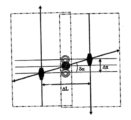
Figure 6: Boat run diagram to determine azimuth deviation
5. Determine horizontal tilt deviation:
Determining horizontal tilt deviation is done as follows:
a) Run a route over a flat seabed surface in both directions. The speed of the two runs remains unchanged;
b) The system must be corrected for identified delays, vertical inclination, and azimuth to avoid interference;
c) This horizontal lateral deviation is determined by measuring the horizontal displacement of the depth measurement data along the vertical direction using the edge beams of the survey lines and calculated according to the formula described in Figure 7; as described in Figure 7
Figure 7: Determining Horizontal Lateral Deviation
Chapter III
SURVEYING, PROCESSING AND ANALYSIS OF DATA
Article 15. Tide gauge observation and data processing
1. Tide gauge observation and data processing at coastal water level stations shall be carried out in accordance with Section 3.10, Appendix 1 of the Technical Regulations on Establishing Marine Topographic Maps at a Scale of 1:50,000.
2. Tide gauge observation using automatic tide recorders at offshore stations:
a) Operation shall comply with the user guide and technical characteristics of the equipment;
b) Recording frequency of water level data shall be set based on data storage capacity and battery endurance to ensure that the obtained water level data is as detailed as possible. The least frequent recording interval is once every hour;
c) Equipment placement: located at the center of the survey area, the equipment placement is determined by the positioning system on the survey vessel, with accuracy ±10m;
d) Data collected over a period of at least 30 days shall be used to analyze the tidal harmonic constants in the survey area.
3. Processing of tide gauge observation data recorded by automatic tide recorders:
a) The mean sea level height of offshore measurement data shall be converted to the mean sea level height observed during the same period at the coastal station (which has been surveyed relative to the national datum). Water level heights at sampling times shall be recalculated based on the converted mean sea level and used to correct the depth measurement data in the survey area;
b) The error in determining the water level height shall not exceed half the depth measurement error.
Article 16. Data Collection
1. Configuration parameters and calibration settings for the survey vessel must be checked before the survey begins.
2. Online monitoring of the data collection process for processing and immediate correction during the survey shift.
3. Prior to surveying, the underwater sound velocity profile must be measured in the survey area and entered into the system for real-time correction during surveying. The sound velocity at the surface of the sound velocity profile must be compared with the sound velocity measured at the transducer head.
4. The speed of the survey vessel must match the design specifications. When the vessel turns, it is necessary to ensure the speed and sufficient time for the wave sensors to stabilize (as required by the wave correction equipment) before entering a new survey line.
5. Depth measurements in the survey area must begin with a cross-line to enable online analysis of the coverage of this cross-line with the first main lines. Depth discrepancies are displayed online using color scales to compare the depth discrepancies between the mid-beams of the cross-line and the mid-beams of the main lines, between the mid-beams of the cross-line and the edge beams of the main lines, and between the edge beams of two adjacent lines.
6. During surveying, the measured data must be monitored. Coverage of the survey tracks and overlap of adjacent tracks must meet the technical requirements of the project. Comparison of data from the edge beams of two adjacent tracks must be conducted. If the measured data exceeds permissible errors, surveying must be temporarily halted to address the issue before continuing.
7. Designed survey lines may be adjusted to fit actual conditions to ensure adequate coverage.
8. Time delay calculation: Data acquisition delay must remain stable like a constant. Surveyors must observe depth and wave measurement data on the graphical window to preliminarily assess the synchronization of these data sources during surveying, and estimate the data delay time. In processing, software with delay calculation functionality must be used to correct the data recording timestamps.
9. Monitor wave effects: Surveyors must track non-wave dynamic influences such as changes in vessel speed and passing vessels, etc., and record these influences for use in data processing. High-precision GPS height (±10cm) with wave correction should be compared with uncorrected wave height to calculate sensor wave measurement errors.
10. After completing each survey line, data must be immediately backed up. Use a copy of the collected data and predicted tide data for the survey area to process data on board. If missing data areas are detected, supplementary measurements must be taken during the survey.
Article 17. Logbook
1. The logbook must be established and fully recorded from the start to the end of the survey.
2. For each survey line, the operator must record the following detailed information:
a) Line name, direction, start time, end time, vessel speed, time and content of new information discovered in the collected data, file name, file path of various types of data;
b) To obtain data for correcting the submergence of the transducer head, the current load weight of oil, water, etc., on the vessel at the beginning and end of the survey period (day) or when oil, water, cargo loading/unloading is completed, including the density of the oil, must be recorded.
Article 18. Real-time data processing
1. Immediately after data backup, a copy of the data must be placed in the real-time processing folder for on-board processing to identify poor quality data areas, missing data, and emerging discrepancies for timely correction.
2. Real-time processing software must allow setting warning limits for measured data so that operators can quickly detect and address issues or poor-quality data.
3. If the software allows real-time plotting, cross-sectional checks must be performed to verify and determine errors (depth and planimetric position differences) between adjacent scan strips. These sections must be drawn and regularly checked along the survey line. If the discrepancy between adjacent survey lines exceeds allowable errors, the cause of the error must be identified and promptly corrected.
Article 19. Post-survey data processing
All original data collected must be separately processed in a dedicated copy. Each version of processed data must be named and stored in a separate directory. The data processing procedure is as follows:
1. Tide gauge data processing, converting observed data to the specified elevation reference plane;
2. Processing positioning data for deep measurement points using post-processing methods.
3. Inputting collected datasets into processing software.
4. Checking the consistency and synchronization of time for tide, positioning, depth measurement, etc., data.
5. Verifying tidal correction factors, positioning delay, horizontal and vertical tilt angles, and remaining ship orientation offsets. Recalculate these correction factors if necessary.
6. Values of waves that do not have a sinusoidal shape and uneven cycles must be marked for careful examination and evaluation.
7. Depending on the software used, apply certain cross-sections of sound speed interpolated over time, distance, position, or selected areas. Analyze depth data to detect remaining depth discrepancies. Change the sound speed correction method or switch to another sound speed cross-section to reduce depth errors.
8. Measured data should be divided into small regions according to the capabilities of each hardware and software (limited number of points) for editing. During editing, remove points with sudden depth changes to avoid losing data for special seabed objects (column-shaped, hanging wire-shaped, pit-shaped, etc.). Smoothing data should only be done after ensuring it does not distort the terrain.
9. Processed data must be converted into compatible X, Y, H format for map editing software and specific databases. For projects carried out based on Technical Regulations for Establishing Seabed Topographic Maps at a Scale of 1:50,000 and Economic and Technical Standards for Surveying and Mapping, data must be extracted along survey lines with spacing meeting the requirements specified in the project.
Chapter IV
ESTABLISHING AND EDITING MAPS
Article 20. Requirements for establishing maps
1. Seabed topographic maps are established according to current regulations corresponding to each scale.
2. For seabed topographic mapping projects based on Technical Regulations for Establishing Seabed Topographic Maps at a Scale of 1:50,000 and Economic and Technical Standards for Surveying and Mapping, the distance between survey lines must meet the requirement of 1 cm on the map (100 meters for a scale of 1:10,000, 500 meters for a scale of 1:50,000).
3. For projects requiring highly detailed surveys, seabed topographic maps established using multi-beam echo sounders must cover the entire seabed. In important maritime areas, multi-beam echo sounding must also ensure detection of objects potentially harmful to passing vessels. The minimum size of objects to be detected is specified in Appendix No. 02 issued together with this Circular.
Article 21. Establishing and Editing Original Digital Seabed Topographic Maps
After obtaining seabed topographic data in X, Y, H format and seabed material information, the establishment and editing of original digital seabed topographic maps shall be carried out in accordance with legal provisions on map establishment and editing.
Chapter V
INSPECTION, ACCEPTANCE, AND SUBMISSION OF PRODUCTS
Article 22. Inspection during production
1. During the process of seabed topographic survey using multi-beam echosounders, measurement cut lines and overlapping sections between adjacent tracks are used to check and evaluate measurement results, identify residual calibration parameter deviations, and adjust the measurement data accordingly.
2. Post-processing depth measurement data must ensure that depth deviation (height) does not exceed 5% for grid cells with values greater than 0.5% of the measured depth.
Article 23. Product acceptance inspection
The inspection and acceptance of seabed topographic map products shall be conducted by the supervising and auditing units according to the Guidelines for Inspection, Audit, and Acceptance of Surveying and Mapping Projects and Products issued together with Circular No. 02/2007/TT-BTNMT dated February 12, 2007, of the Ministry of Natural Resources and Environment.
Article 24. Submitted products
1. Measurement test and system calibration results;
2. The technical summary report must detail the equipment used, measurement methods, data recording, data processing procedures, description of testing and calibration processes, sound speed used for depth calculations, point filtering processes, raw data corrections, and the accuracy of the obtained results;
3. Digital seabed topography model;
4. Seabed topographic map;
5. Construction units are responsible for submitting and storing seabed topographic map survey and mapping products and original documents in accordance with current legal provisions.
Chapter VI
IMPLEMENTATION
Article 25. Implementation Provisions
This Circular takes effect from January 1, 2011.
The Director of the Vietnam Marine Administration is responsible for guiding, monitoring, and inspecting the implementation of this Circular.
Any issues encountered during implementation should be promptly reported to the Ministry of Natural Resources and Environment for research, amendment, and supplementation as appropriate.
|
DEPUTY MINISTER
|
Văn bản gốc (PDF)
Tải văn bản
Bản đồ quan hệ
Bấm vào một văn bản để mở. Viền đỏ = quan hệ làm thay đổi hiệu lực.
Bản dịch
Văn bản này có sẵn ở các ngôn ngữ sau: