
These regulations specify grounding and earthing requirements for telecommunication stations to ensure electrical safety, reduce electromagnetic interference, and enhance the operational efficiency of telecommunication equipment systems.
适用范围
Telecommunication stations such as mobile base stations, transmission stations, satellite stations, fixed switchboards, data communication stations, and similar stations.
要点
- The TN-S network must be used for the AC power distribution system within telecommunication stations.
- Ensure earthing for all DC conductors serving the telecommunication equipment system.
- Connect all MESH-BN networks with the CBN at multiple points.
- Power supply and signal cables must run close and parallel to the CBN.
- Ensure that the DC voltage on each conductor is less than 1V.
🌐 本文件的社会影响
- Enhance safety for users and telecommunication equipment.
- Minimize the risk of fire and explosion due to electrical short circuits.
- Improve the quality of transmitted signals.
- Save energy by reducing electromagnetic interference.
❓ 常见问题
Why must the TN-S network be used for the AC power distribution system in telecommunication stations?
The TN-S network separates the protective earth (PE) and neutral (N) wires, thereby minimizing the risk of circuit breakage causing fires and explosions.
The DC voltage on each conductor must be less than 1V, why?
To ensure safety for users and telecommunication equipment, preventing electric shock due to potential differences between contact points.
全文
|
MINISTRY INFORMATION AND COMMUNICATIONS |
SOCIALIST REPUBLIC OF VIET NAM |
|
Number: 26/2016/TT-BTTTT |
Hanoi, on 07 the 12 2016 |
CIRCULAR
ISSUES "NATIONAL TECHNICAL REGULATION ON EARTHING FOR TELECOMMUNICATION STATIONS"
Pursuant to the Law on Standards and Technical Regulations dated June 29, 2006;
Pursuant to the Law on Telecommunications dated November 23, 2009;
WHEREAS, Decree No. 127/2007/NĐ-CP dated August 1, 2007 of the Government detailing and guiding the implementation of certain provisions of the Law on Technical Standards and Regulations;
Based on Decree No. 132/2013/ND-CP dated October 16, 2013 of the Government on the functions, tasks, powers, and organizational structure of the Ministry of Information and Communications;
Pursuant to the proposal of the Director of the Science and Technology Department,
The Minister of Information and Communications issues this Circular to regulate the National Technical Regulation on Earthing for Telecommunication Stations.rime Minister cThis Circular stipulates the National Technical Regulation on Earthing for Telecommunication Stations.
Article 1. Accompanying this Circular is the National Technical Regulation on Earthing for Telecommunication Stations (QCVN 9:2016/BTTTT).
Article 2. This Circular takes effect from May 1, 2017. The National Technical Regulation on Earthing for Telecommunication Stations, designated as QCVN 9:2010/BTTTT, as stipulated in Clause 8, Article 1 of Circular No. 18/2010/TT-BTTTT dated July 30, 2010, issued by the Minister of Information and Communications regarding National Technical Regulations on Telecommunications, shall cease to have legal effect from the date this Circular takes effect.
Article 3. The Heads of the Office, Department of Science and Technology, Heads of agencies and units under the Ministry of Information and Communications, Directors of Provincial Departments of Information and Communications, centrally-run cities, and relevant organizations and individuals are responsible for implementing this Circular./.
|
|
THE MINISTER |
QCVN 9:2016/BTTTT
NATIONAL TECHNICAL REGULATION ON EARTHING FOR TELECOMMUNICATION STATIONS
National technical regulation on earthing for telecommunications stations
TABLE OF CONTENTS
Chapter 1. GENERAL PROVISIONS
1.1. Scope of Application
1.2. Applicability
1.3. Referenced Documents
1.4. Terms and Definitions
1.5. Abbreviations
Chapter 2. TECHNICAL PROVISIONS
2.1. Earthing system
2.1.1. Earth electrode
2.1.2. Main earth plate
2.1.3. Earthing conductor
2.2. Connection configuration
2.2.1. Internal building communication network (CBN) within telecommunication station
2.2.2. Interconnection network within telecommunication equipment system
2.2.3. Connection between CBN network and MESH-BN networks
2.2.4. Connecting cable between MESH-BN networks
2.3. Earthing for power distribution systems
2.3.1. Secondary power supply DC distribution
2.3.2. Third-level power supply DC distribution
2.3.3. AC power supply distribution and protective conductor connection
2.3.4. AC power distribution from third-level power supply
3. MANAGEMENT PROVISIONS
4. RESPONSIBILITIES OF THEỔ OFFICIAL, INDIVIDUAL
Chapter 5. ORGANIZATION OF IMPLEMENTATION
ANNEX A (Provisions) Method for measuring earth resistance
LIST OF REFERENCES
Foreword
QCVN 9:2016/BTTTT replaces QCVN 9:2010/BTTTT.
The technical provisions of QCVN 9:2016/BTTTT comply with the technical provisions of standard ETSI EN 300 253 V.2.2.1 (2015-06) and recommendation ITU-T K27 (3/2015).
QCVN 9:2016/BTTTT was compiled by the Institute of Post and Telecommunications Engineering Sciences, reviewed and approved by the Department of Science and Technology, and issued together with Circular No. 26/2016/TT-BTTTT dated December 7, 2016.
NATIONAL TECHNICAL REGULATION ONMOBILE SATELLITE EARTH STATIONN TECHNICAL REGULATION ON EARTHING FOR TELECOMMUNICATION STATIONS
National technical regulation on earthing of telecommunications stations
Chapter 1. GENERAL PROVISIONS
1.1. Scope of Application
This regulation specifies technical requirements for earthing of telecommunications stations including requirements for earthing systems, internal building communication networks, interconnections among equipment, and connections between these networks.
This regulation applies to telecommunications stations during design, construction, operation, and maintenance.
Telecommunications stations referred to in this regulation include the following facilities:
- Switching centers, transmission centers;
- Data centers (datacenters);
- Fixed radio stations used for fixed wireless services, mobile communications, aviation, maritime, navigation, positioning, satellite, broadcasting, amateur services;
- Radio and television stations.
This regulation does not apply to subscriber premises.
1.2. Applicability
This technical regulation applies to agencies, organizations, and individuals involved in establishing, managing, and operating telecommunications stations as specified in Section 1.1 in Vietnam.
1.3. Referenced Documents
QCVN 32:2011/BTTTT, National Technical Regulation on Lightning Protection for Telecommunications Stations and Perimeter Cable Networks.
1.4. Terms and Definitions
1.4.1. Earthing conductor (earthing conductor)
Protective conductor connecting the main earth plate to the earth electrode.
1.4.2. Earth (earth)
An electrically conductive mass where the potential at every point is conventionally taken as zero.
1.4.3. Earth electrode (earth electrode)
A conductive part or group of conductive parts in good contact with the earth and providing an electrical connection to it.
1.4.4. Equipotential bonding (equipotential bonding)
Electrical connection to place metallic components that are not insulated and external conductive components at a stable balanced potential.
1.4.5. Equipotential bonding conductor (equipotential bonding conductor)
Protective conductor ensuring equipotential bonding.
1.4.6. Main earth plate (MET)
An electrode or bar used to connect protective conductors, equipotential bonding conductors, and operational earthing conductors (if present), to the earth electrode.
NOTE: In practice, the main earth plate is usually a nickel-plated copper sheet with holes drilled, mounted on bakelite and securely fastened to the wall.
1.4.7. Neutral conductor (N- Neutral conductor)
Conductor connected to the neutral point of a system and participating in the transmission of electrical energy.
1.4.8. Protective conductor (protective conductor)
Conductor required for certain measures to protect against electric shock by connecting to the following parts:
- Exposed conductive parts;
- External conductive parts;
- Main earth plate;
- Earth electrode;
- Artificial neutral or earthed point of the source.
1.4.9. Protective neutral conductor (PEN conductor)
Conductor combining the functions of a protective conductor and a neutral conductor.
1.4.10. IT Network (Insulation Terrestrial)
Low-voltage network with isolated neutral point and equipment enclosures connected to independent protective earthing.
1.4.11. TN-S Network C (Terrestrial Neutral Separated)
TN network with separate protective conductor and neutral conductor (PEN). Exposed conductive parts (enclosures of electrical equipment) are connected to the protective earth conductor (PEN).
1.4.12. TN-C Network (Terrestrial Neutral)
Low-voltage network with neutral point directly grounded.
1.4.13. TN-C-S Network Provincial People's Committees set specific prices (Terrestrial Neutral Combined)
TN network with combined protective conductor and neutral conductor (PEN). Exposed conductive parts (enclosures of electrical equipment) are connected to the protective earth conductor (PE). The protective earth conductor (PE) may be the metal sheath of the power cable or a separate conductor.
1.4.14. Bonding mat (bonding mat)
Essential means to create a system reference plane potential (SRPP) using a similar mesh structure.
NOTE: The bonding mat can be placed above or below a group of equipment forming a system block.
1.4.15. Building network (BN)
A set of interconnected conductive elements designed to shield electronic systems and people from electromagnetic interference.
1.4.16. Common building network (CBN)
A set of metallic elements randomly or intentionally connected to form a primary bonding network within a telecommunications building.
1.4.17. Mesh Bonding Network (Mesh -BN)
A bonding network where all equipment frames, racks, cabinets, and positive DC power supply wires are interconnected with the common bonding network (CBN) at multiple points.
1.4.18. Isolated Mesh Bonding Network (Mesh- IBN)
An isolated bonding network wherein its components (equipment racks) are interconnected to form a mesh structure.
1.4.19. Primary Supply (primary supply)
Public utility power grid, or, in emergency situations, AC generator power within the area.
1.4.20. Secondary Supply (secondary supply)
Power supplied to telecommunications equipment, racks, or system blocks derived from the primary supply.
1.4.21. Tertiary Supplies (tertiary supplies)
Power supplied to telecommunications equipment derived from the secondary supply.
1.4.22. System (system)
A group of interacting devices forming a unified entity.
1.4.23. System Block (system block)
A functional group of equipment operating on a common system potential reference plane, connected to a Mesh-BN.
1.4.24. System Reference Potential Plane (SRPP)
A conductive plane for potential equalization, implemented through vertical or horizontal grids.
NOTE 1: The width of the mesh is adjusted according to the frequency range considered. Horizontal and vertical mesh sheets can be interconnected to form a structure similar to a Faraday cage.
NOTE 2: SRPP supports signaling with a common system potential reference.
1.4.25. Isolated DC Return (isolated DC return) (DC - I)
A DC power system in which the return wire (positive DC power wire) has a single point connection to the bonding network.
1.4.26. Common DC Return (common DC return) (DC - C)
A DC power system in which the return wire (positive DC power wire) is connected to the bonding network at multiple points.
1.4.27. Telecommunications Station
A building housing one or more telecommunications equipment systems.
1.5. Abbreviations
|
AC |
Alternating Current |
Continuous phenomenon applicable to receivers |
|
BN |
Bonding Network |
Bonding Network |
|
CBN |
Common Bonding Network |
Common Bonding Network |
|
DC |
2.1 Electromagnetic Compatibility (EMC) Emission |
Discontinuous phenomenon applicable to transmitters |
|
EMC |
ElectroMagnetic Compatibility |
ElectroMagnetic Compatibility |
|
LPS |
Lightning Protection System |
Lightning protection system |
|
MESH- BN |
Meshed Bonding Network |
Mesh bonding network |
|
MESH- IBN |
MESHed Isolated Bonding Network |
Isolated mesh bonding network |
|
MET |
Main Earthing Terminal |
Main earthing terminal |
|
N ||| |
Neutral Conductor |
Neutral conductor |
|
PE |
Protective Conductor |
Protective conductor |
|
PEN |
Combined Protective Conductor and Neutral Conductor |
Combined protective conductor and neutral conductor |
|
RF |
Radio Frequency |
Radio Frequency |
|
SRPP |
System Reference Potential Plane |
System reference potential plane |
Chapter 2. TECHNICAL PROVISIONS
2.1. Earthing system
2.1.1. Earth electrode
- Grounding assemblies must have a ground resistance value not exceeding 10 Ω. The method of measuring ground resistance is specified in Appendix A of this standard.
- Grounding assemblies must be connected to the main earthing terminal using grounding cables.
NOTE: The ground resistance value may comply with the manufacturer's equipment standards but must ensure that it does not exceed 10 Ω.
2.1.2. Main earth plate
a) Specifications, dimensions
- The main earthing terminal must be made of nickel-plated copper.
- All bolts, nuts, and washers used to terminate grounding cables must be nickel-plated copper.
- Dimensions: minimum width of 120 mm, minimum thickness of 10 mm, and minimum length of 300 mm.
b) Direct connections to the following parts:
- Grounding assembly of the telecommunications station via grounding cables;
- Protective conductors;
- Metal casings of all incoming telecommunications cables;
- CBN network;
- Positive DC power supply terminal.
NOTE: The main earthing terminal should be placed near the AC power supply source and the incoming telecommunications cable routes.
2.1.3. Earthing conductor
- The length of the grounding cable must not exceed 50 m. In special cases, the length of the grounding cable may be increased but must ensure that the one-way resistance of the grounding cable is less than or equal to 0.01 Ω.
- Use copper cable(s) (single or multiple strands) with a total cross-sectional area of no less than 100 mm².2.
2.2. Connection configuration
2.2.1. Internal building communication network (CBN) within telecommunication station
The telecommunications station must implement a common bonding network (CBN).
The CBN network must be connected to the main earthing terminal by a continuous loop around the inner perimeter of the building; or the basic component of the CBN, a ring conductor, must encircle the system block. The CBN network must be capable of expanding into a three-dimensional mesh structure to accommodate additional telecommunications equipment systems in the station.
The CBN network must ensure a continuous conductive Faraday cage surrounding the entire telecommunications station as shown in Diagram 1.
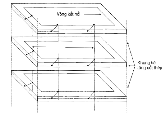
Diagram 1 - CBN Network
The CBN network consists of the following components:
- A closed-loop connection at each floor level of the building, around the floor or around the walls. For the first floor, it is implemented under the floor at a depth of 0.5 m to 0.7 m. The loop connection is made using copper cables or strips of copper or zinc-coated steel with a minimum cross-sectional area of 50 mm².2;
- Vertical connecting wires linking the loops of each floor, with a distance between vertical wires not exceeding 5 m. The vertical connecting wires are copper or zinc-coated steel bars with a minimum cross-sectional area of 50 mm².2;
NOTE: The structural steel frame of the building can be utilized as part of the CBN network, provided that the steel components are welded together to ensure continuous conductivity.
Implement the connection of the bonding conductors to the metallic components in the telecommunications station as follows:
- All lightning arrestor wires of the telecommunications station;
- The entire reinforced concrete frame of the station structure;
- Cable support frames for incoming telecommunications cables;
- Water pipes and metal cable conduits.
2.2.2. Interconnection network within telecommunication equipment system
Within a system block of telecommunications equipment, the bonding network must be in the form of a mesh (MESH- BN).
The MESH- BN network must connect equipment frames, machine casings, conduits, trays, wiring racks, cable jackets, and connection pads to form a system reference potential plane (see 1.4.24).
All metallic components of the MESH- BN must form a continuous electrical whole (see Diagram 2).
The mesh bonding network (MESH- BN) must meet the following requirements:
a) Mesh pad
- The mesh pad must be large enough to accommodate the equipment and cable racks within the MESH- BN system block and placed under the equipment floor.
- The pad is made of bare copper or zinc-coated steel strips with a minimum cross-sectional area of 14 mm²2 and welded into a mesh.
- The size of the mesh net opening shall be within the range:
20 cm x 20 cm;
30 cm x 30 cm;
40 cm x 40 cm;
50 cm x 50 cm.
b) Connect the mesh net padding to the CBN network at multiple points (the more connection points with the CBN network, the better) using bare copper wire or galvanized steel wire with a minimum cross-sectional area of 14 mm²2.
c) Connect the lead portion of the telecommunication equipment system to the mesh net padding
- Telecommunication equipment with electronic circuits is provided with a common metal shielding layer creating a reference potential plane covering the entire surface of the printed circuit boards. All reference potential planes are connected to each other and to the equipment rack or the metal jacket of the adjacent cable system (located within the M-BN block) using wires with a minimum cross-sectional area of 14 mm²2.
- Connect the jackets, equipment racks, and metal jacketed cables to the mesh net padding using the shortest possible copper wire (strip). The cross-sectional area of the connecting wire is specified in Table 1.
Table 1 - Cross-sectional area of connecting wires to the mesh net padding
|
No. |
Name of connecting wire |
Minimum cross-section, mm²2 |
|
1 |
Connecting wire for the metal jacket of subscriber cable (buried) |
14 |
|
2 |
Connecting wire for the metal jacket of subscriber cable (hung) |
14 |
|
3 |
Connecting wire for subscriber protection equipment on the distribution frame MDF |
14 |
|
4 |
Connecting wire for AC power protection equipment |
35 |
|
5 |
Connecting wire for battery ground |
14 |
|
6 |
Connecting wire for the metal part of the rack of the rectifier |
14 |
|
7 |
Connecting wire for the rack of the power converter |
14 |
|
8 |
Connecting wire for the metal parts of the rack of the switchboard |
14 |
|
9 |
Connecting wire for the metal parts of the rack of the distribution frame |
14 |
|
10 |
Figure 2 - MESH-BN network connected to CBN |
14 |
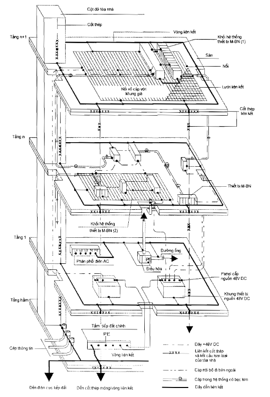
All MESH-BN networks of telecommunication equipment systems and accompanying return DC lines must be connected to the CBN. The MESH-BN network connects to the CBN at multiple points and connects to the main grounding bar (see Figures 2, 3, and 4).
2.2.3. Connection between CBN network and MESH-BN networks
If the equipment operates with a shared return DC line (as designed), this shared return DC line must be connected to the CBN at multiple points (see Figure 3).
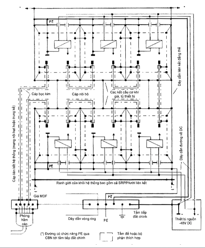
If the equipment operates with an isolated return DC line, then this isolated return DC line must connect to the CBN at one point (see Figure 4).
Figure 3 - CBN/MESH-BN with shared return DC line connected to CBN at multiple points
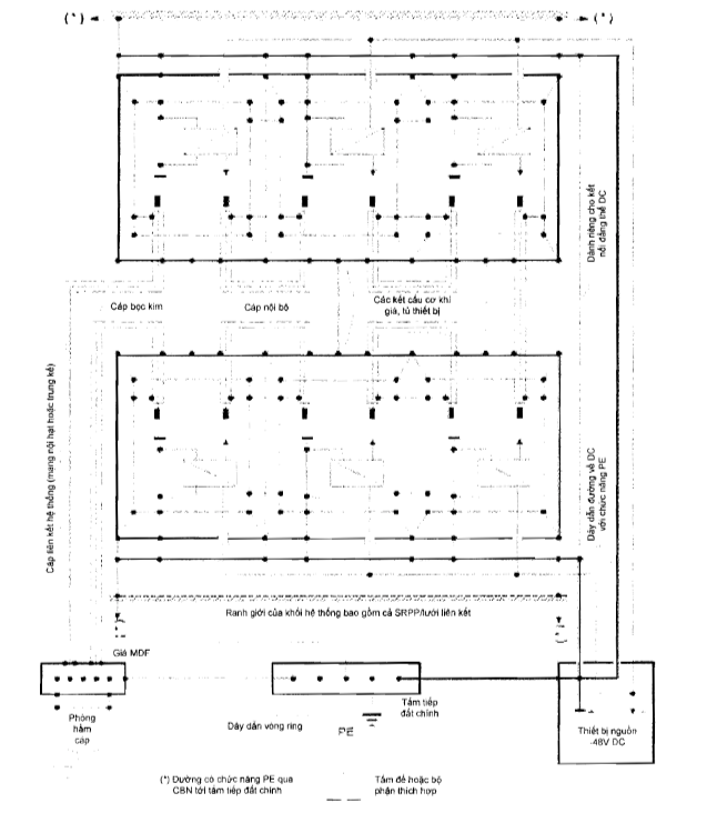
Figure 4 - CBN/MESH-BN with isolated return DC line, connected to CBN at one point
Distribution power cables and signal cables inside and between MESH-BN must run close and parallel to the CBN.
2.2.4. Connecting cable between MESH-BN networks
AC power cables and signal cables must be placed at least 100 mm apart unless there are appropriate shielding measures.
Cable jackets must be connected to the rack, machine housing, or SRPP at both ends of the cable.
Each DC return line serving a telecommunication equipment system must be connected to the CBN network at least at the main grounding bar, at the DC power supply panel, and connected to the MESH-BN network at least at one point.
2.3. Earthing for power distribution systems
2.3.1. Secondary power supply DC distribution
The DC voltage along each DC return line must be less than 1 V. Design calculations must consider the maximum load current on the accompanying power supply line under the highest or lowest source voltage conditions, during normal operation.
The end of the DC return line of the power supply network for the telecommunication equipment system must be grounded at the power supply panel by connecting to the main grounding bar.
The positive terminal of the third-level power supply must be connected to the MESH-BN.
2.3.2. Third-level power supply DC distribution
In telecommunication stations, the AC power supply system must use the TN-S network type. The three-phase power system must be a five-wire system (L1, L2, L3, N, PE), where: L1, L2, L3 are phase wires; N is the neutral wire; PE is the protective earth wire. The protective earth wire PE must be connected to the main grounding bar. There should be no common connection point between the protective earth wire PE and the neutral wire N.
2.3.3. AC power supply distribution and protective conductor connection
a) If the external AC power distribution network is of the TN-S type, the AC power supply circuit in the telecommunication station must be connected as shown in Diagram 5.a, wherein:
- The protective earth wire PE must be connected to the main grounding bar;
- The neutral wire N must not be connected to the main grounding bar.
b) If the external AC power distribution network is a four-wire system (IT or TT), the AC power supply circuit in the telecommunication station must be connected as shown in Diagram 5.b, wherein:
- The protective earth wire PE must be connected to the main grounding bar.
c) If the external AC power distribution network is a four-wire system (IT or TT) and uses an isolation transformer for the station, the AC power supply circuit in the telecommunication station must be connected as shown in Diagram 5.a.
NOTE: Type a) is mandatory if the building uses an isolation transformer and thus the TN-S system starts from the load side of the transformer.
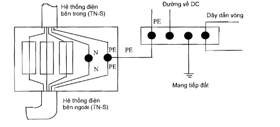
a) External AC power distribution network is of the TN-S type
b) External AC power distribution network is of the IT or TT type
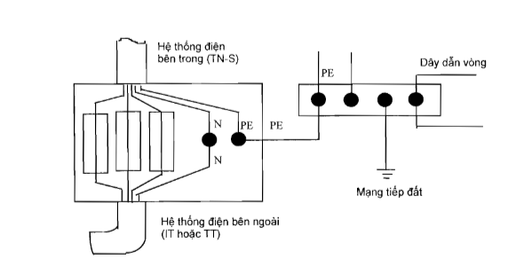
Figure 5 - Method of connecting the external AC power distribution network for telecommunication stations
2.3.4. AC power distribution from the third-level power supply
The neutral point of the third-level power supply must be taken by connecting the star network's neutral point or the outer conductor to the MESH-BN at the power source. Power distribution to the load must follow the rules of the TN-S system.of the Government stipulating functions, tasks, powers, and organizational structure of the Ministry of Home AffairsTelecommunication stations within the scope regulated in Section 1.1 must comply with the provisions of this Standard.
Agencies and organizations establishing, managing, and operating telecommunication stations as stipulated in Section 1.1 are responsible for ensuring compliance with this Standard during design, installation, operation, maintenance, and are subject to inspection by the competent state management agency as prescribed.
3. MANAGEMENT PROVISIONS
Agencies and organizations managing and operating telecommunication stations as stipulated in Section 1.1 are responsible for implementing commitments to comply with this standard based on the technical documentation of the telecommunication station and announcing compliance with the telecommunication stations in accordance with Section 2.1.1 of this standard. Compliance announcement is carried out in accordance with Circular No. 28/2012/TT-BKHCN dated December 12, 2012, of the Ministry of Science and Technology.
4. RESPONSIBILITIES OF ORGANIZATIONS AND INDIVIDUALS
4.1. The Telecommunications Authority is responsible for receiving declarations of compliance announcement, managing, guiding, and inspecting compliance announcements.
4.2. The Telecommunications Authority and Provincial Departments of Information and Communications are responsible for organizing guidance, implementation, and management of telecommunication stations in compliance with this Standard.
4.3. This Standard replaces National Technical Regulation QCVN 9:2010/BTTTT "National Technical Regulations on Grounding for Telecommunication Stations".
Chapter 5. ORGANIZATION OF IMPLEMENTATION
5.1. Grounding resistance measurement method
5.2. A.1. Voltage drop measurement method
5.3. In cases where the provisions set forth in this Standard are changed, supplemented, or replaced, they shall be implemented according to the new document.
A.1. Measurement Server
Product Name, Goods According to QCVN
E connected to the grounding grid to be measured
A.1. Method for measuring voltage drop
E connected to the earthing assembly to be measured
P, C - Points connecting to test electrodes
Diagram A.1 - Earth resistance measurement diagram
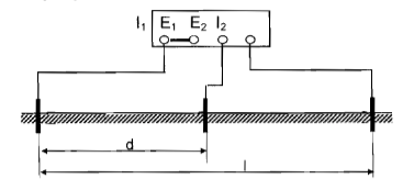
Earth system measurement is carried out using a three-electrode or four-electrode earth resistance meter.
The measurement diagram is shown in Diagram A.1.
To ensure accurate earth resistance measurement results:
- The frequency emitted by the meter differs from n x 50 Hz;
- Test electrodes (voltage electrodes and current electrodes) must be arranged outside the influence area of the earth electrode and must ensure that the distance from the earth electrode to be measured to the voltage electrode equals 62% of the distance from the earth electrode to be measured to the current electrode (in the case where the test electrodes are arranged in a straight line).
The arrangement of test electrodes for the case of a vertical earth electrode is presented in Diagram A.2, and for an earth grid or multiple earth electrodes in Diagram A.3.
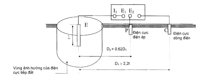
Diagram A.2 - Earth resistance measurement diagram of a vertical earth electrode
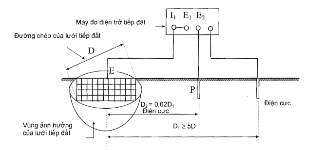
Diagram A.3 - Earth resistance measurement diagram of an earth grid or multiple earth electrodes
LIST OF REFERENCES
[1] ITU-T, Recommendation K27 (03/2015), Bonding Configurations and Earthing Inside a Telecommunication Building.
[2] ETSI EN 300 253 V.2.2.1 (2015-06) Environmental Engineering (EE); Earthing and Bonding of ICT Equipment Powered by -48 VDC in Telecom and Data Centres.
[3] J-STD-607-A (2002), Commercial Building Grounding (Earthing) and Bonding Requirements for Telecommunications.
[4] R56 (1/2005), Motorola, Standards and Guidelines for Communication Sites.
[5] Cisco Hardware Installation Guide, 10/2002.
原始文件(PDF)
关系图
点击文件即可打开。红色边框=改变效力的关系。