
This Circular stipulates the technical procedures for airborne magnetic and gravity surveys serving geological work and mineral prospecting. It includes contents such as purpose, scope of application, technical requirements, implementation organization, methods and working procedures, as well as the final products of this work.
Scope of application
Ministries, ministerial-level agencies, agencies under the Government, People's Committees of provinces and centrally governed cities, and organizations and individuals related to geological work and mineral prospecting.
Key points
- Provisions regarding the purpose and scope of application of airborne magnetic and gravity surveys.
- Technical requirements for equipment and means used in this work.
- Implementation of airborne magnetic and gravity surveys, including project planning, implementation organization, and quality management.
- Methods and working procedures during the implementation of this work.
- Final products of airborne magnetic and gravity surveys.
🌐 Social impact of this document
- Enhance the effectiveness of geological work and mineral prospecting through the use of advanced technology.
- Help accurately and effectively identify and exploit mineral resources.
- Strengthen environmental management and protection during mineral exploitation.
❓ Frequently asked questions
When does this Circular take effect?
This Circular takes effect from February 15, 2019.
Which previous regulations are abolished upon issuance of this Circular?
Regulations related to airborne gravity surveys serving geological work and mineral prospecting stipulated in Circular No. 08/2012/TT-BTNMT dated August 8, 2012, issued by the Minister of Natural Resources and Environment shall cease to be effective from the date this Circular takes effect.
Full text
|
MINISTRY OF NATURAL RESOURCES AND ENVIRONMENT Number: 28/2018/TT-BTNMT |
SOCIALIST REPUBLIC OF VIET NAM Hanoi, December 26, 2018 |
CIRCULAR
Technical regulations for magnetic and gravity survey flights in geological and mineral exploration activities
Article 1. These technical regulations apply to magnetic and gravity survey flights in basic geological surveys and mineral exploration activities.
Pursuant to the Minerals Law 2010;
Pursuant to the Civil Aviation Law of Vietnam 2006;
Pursuant to the Law Amending and Supplementing Certain Provisions of the Civil Aviation Law of Vietnam 2014;
Pursuant to Decree No. 158/2016/NĐ-CP dated November 29, 2016 of the Government detailing certain provisions of the Minerals Law;
Pursuant to Decree No. 36/2017/NĐ-CP dated April 4, 2017 of the Government stipulating the functions, tasks, powers, and organizational structure of the Ministry of Natural Resources and Environment;
Based on the proposal of the Director General of the Vietnam Geological and Mineral Resources Administration, the Head of the Science and Technology Department, and the Head of the Legal Affairs Department;
The Minister of Natural Resources and Environment promulgates this Circular on technical regulations for magnetic and gravity survey flights in basic geological surveys and mineral exploration activities.
PART I
GENERAL PROVISIONS
Article 1. Scope of Regulation
1. This Circular sets forth technical regulations for magnetic and gravity survey flights in basic geological surveys and mineral exploration activities conducted within the territory of Vietnam.
2. This Circular does not apply to the use of satellites or unmanned aerial vehicles for magnetic and gravity measurements in basic geological surveys and mineral exploration activities.
Article 2. Applicability
This Circular applies to state management agencies for minerals, organizations, and units conducting magnetic and gravity survey flights in basic geological surveys and mineral exploration activities.
Article 3. Explanation of Terms
Strategic multi-purpose hydropower plant
1. Magnetic flight measurement method is a method of measuring magnetic field values using specialized equipment installed on aircraft.
2. Gravity flight measurement method is a method of measuring gravity field values using specialized equipment installed on aircraft.
3. Normal gravity field is the value of the gravity field calculated on the theoretical surface of the Earth, which has an ellipsoidal shape.
4. Gravity measurement result correction involves calculations to eliminate the effects of factors such as altitude, intermediate layer, terrain, aircraft motion effect, tides, and Earth's curvature on the measurement results.
5. The Earth's magnetic field is a vector quantity. The intensity value of the magnetic field is called the total magnetic field, denoted as T.
6. The normal magnetic field (denoted as T°) is a conventional concept calculated from measured values at points considered to have no magnetic anomalies.
7. Magnetic anomaly (denoted as ΔTa) is the difference between the measured magnetic field value after corrections and tie-in (denoted as T) and the normal magnetic field value T° at a measurement point: ΔTa = T - T0.
8. Flight measurement line network consists of regular flight measurement line networks, tie-flight measurement line networks, check-flight measurement line networks, and tie-in-flight measurement line networks.
9. Regular flight measurement line network is a network designed according to the mapping scale for magnetic and gravity survey flights over the entire flight area.
10. Tie-flight measurement line network is a network used to tie magnetic and gravity data within a flight area.
11. Check-flight measurement line is a selected line for flying to check the system of measurement and recording equipment for each flight.
12. Tie-in-flight measurement line is a line for tying magnetic and gravity measurement data between different flight areas.
13. Abbreviations used in this Circular are defined in Table 1 as follows:
Table 1. Abbreviations
|
Serial No. |
Code |
Meaning |
|
1 |
Deviaxia |
Effect of flight direction on magnetic measurement results |
|
2 |
Eotvot |
Aircraft motion effect on gravity measurement results |
|
3 |
DEM |
Digital elevation model |
|
4 |
nT |
NanoTesla, unit for measuring magnetic field |
Article 4. Network of survey flight routes for measurement, altitude, and speed
1. The network of survey flight routes for measuring direction and gravity shall be carried out at the investigation scale; the distance between regular survey flight routes and the distance between auxiliary survey flight routes are specified in Table 2 of this Clause.
Table 2. Distance of the network of survey flight routes
|
Serial number |
Investigation Scale |
Distance Between regular survey flight routes (m) |
Auxiliary survey flight route distance (m) |
|---|---|---|---|
|
1 |
1:1.000.000 |
10.000 |
Within the range from 30,000 to 50,000 |
|
2 |
1:500.000 |
5.000 |
Within the range from 15,000 to 25,000 |
|
3 |
1: 250.000 |
2.500 |
Within the range from 7,500 to 12,500 |
|
4 |
1: 200.000 |
2.000 |
Within the range from 6,000 to 10,000 |
|
5 |
1:100.000 |
1.000 |
Within the range from 3,000 to 5,000 |
|
6 |
1:50.000 |
500 |
Within the range from 1,500 to 2,500 |
|
7 |
1:25.000 |
250 |
Within the range from 750 to 1,250 |
|
8 |
1:10.000 |
100 |
Within the range from 300 to 500 |
2. The distance between regular survey flight routes during actual flights shall not deviate more than one-third (1/3) of the distance between two adjacent routes compared to the design.
3. Design requirements for the direction (orientation) of survey flight routes:
a) The direction of regular survey flight routes shall be designed perpendicular or nearly perpendicular to the general geological structure direction of the flight area but not less than 45 degrees.0;
b) The direction of auxiliary survey flight routes shall be designed perpendicular to the regular survey flight routes;
c) Regular survey flight routes shall not be designed in the direction of 90 degrees0 or 270 degrees0 for magnetic survey flights.
4. Requirements for designing connecting survey flight routes:
a) Connecting survey flight routes shall be designed to overlap both survey areas on regions with stable magnetic field characteristics;
b) The connection between two survey areas must have at least three connecting survey flight routes; the length of each connecting survey flight route overlapping each survey area must be at least 10 km.
5. The maximum flight altitude for regular and auxiliary survey flight routes for magnetic and gravity surveys is 500 meters above the highest point of the terrain along the flight route, except for the flight altitudes specified in Clause 2, Article 17, Point b, Clause 2 and Point b, Clause 3, Article 18, Clause 2, Article 37, and Clause 1, Article 38 of this Circular. The specific flight altitude is determined according to the project, program, or task (hereinafter referred to as the project) approved by the competent state authority.
6. Requirements for flight speed:
a) Magnetic survey flight speed ≤ 500 km/h;
b) Gravity survey flight speed ≤ 250 km/h and maintain a constant speed throughout the entire survey flight process.
Article 5. Preparation for conducting magnetic and gravity survey flights
1. Units responsible for conducting magnetic and gravity survey flights shall be responsible for:
a) Coordinating with service providers to apply for flight permits and notify flight plans in accordance with the law;
b) Registering state activities related to basic geological surveys and mineral exploration;
c) Considering and evaluating climatic and weather conditions, topography to calculate appropriate survey flight times;
d) Inspecting, testing, and calibrating equipment used for survey flights in accordance with the law;
đ) Preparing relevant materials and supplies;
e) Transporting equipment and personnel to the survey area.
2. Preparations before each survey flight:
Units assigned the task of conducting magnetic and gravity survey flights and related units shall be responsible for:
a) Implementing the provisions of Clause 1 of this Article;
b) Checking the operation of the entire measurement equipment system;
c) Determining flight conditions and flight plans;
d) Implementing survey flight procedures in accordance with the law.
Article 6. Prevention, response, and resolution of incidents during survey flights
1. Units assigned the task of conducting magnetic and gravity survey flights and related agencies and units according to their functions and responsibilities shall be responsible for implementing measures to prevent, respond to, and resolve incidents during survey flights.
2. Prevention, response, and resolution of incidents during survey flights shall be carried out in accordance with the law.
Article 7. Forms of aerial magnetic and gravity survey operations
For each magnetic or gravity survey flight project, the unit assigned the task of conducting surveys must implement the following forms of flight operations: reconnaissance flights, technical measurement flights, production measurement flights, and field transfer flights, specifically as follows:
1. Conducting comprehensive reconnaissance flights over the entire survey area to determine topographical conditions, terrain features, climate, takeoff and landing conditions for the purpose of serving the development of safe, reasonable, and effective flight plans.
2. Technical measurement flights include the following types of flights:
a) Flights to check equipment and determine technical parameters. For magnetic surveys, it is necessary to conduct magnetic compensation flights, flights to determine the influence of the magnetic field along the flight path, and flights to determine the delay of the recording equipment. For gravity surveys, it is necessary to conduct flights on standard flight paths as prescribed in Clause 2, Article 38 of this Circular to check the gravity measuring equipment;
b) Flights to select and check flight paths;
c) Flights to measure along pre-designed reference flight paths and connecting flight paths.
3. Production measurement flights involve conducting magnetic and gravity survey flights according to pre-designed flight paths.
4. Field transfer flights involve transferring aircraft from one airport to another during the implementation of the project.
Article 8. Installation and dismantling of machines and equipment
1. The installation of magnetic and gravity measuring devices and related equipment shall be carried out in accordance with technical regulations and aircraft design specifications provided by the supplier.
2. Installation work ensures the connection of the entire system of machines and related equipment (data collection systems, GPS navigation positioning systems, height measurement equipment); operational checks ensure that the entire system of machines and equipment operates normally.
3. Dismantling of machines and related equipment shall be carried out in the following cases:
a) At the end of the flying season;
b) Regular maintenance of the aircraft as stipulated by law or by the manufacturer;
c) When the aircraft, machines, and related equipment have malfunctions or do not meet safety requirements for flying.
Article 9. Supervision of magnetic and gravity survey operations; inspection, acceptance, and verification of survey results
1. Supervision of magnetic and gravity survey operations shall be conducted in accordance with the law throughout the entire process from the installation and dismantling of machines and equipment until the completion of the survey operations.
2. Inspection, acceptance, and verification of magnetic and gravity survey results shall be carried out in accordance with current regulations on geological investigations and mineral exploration and other relevant laws.
Article 10. Preservation, exploitation, use, and publication of information
Preservation, exploitation, use, and publication of information, data, and results of magnetic and gravity survey operations shall be carried out in accordance with the law.
Chapter II
GEODETIC POSITIONING AND NAVIGATION LINE SURVEY WORK MAGNETIC AND GRAVITY SURVEY FLIGHTS
Article 11. Technical requirements for geodetic positioning and navigation line survey work for magnetic and gravity survey flights
1. Prior to each flying season, the positioning and navigation system (GPS) must be checked for coordinate and altitude parameters at national geodetic markers and at the location where the GPS is installed on the aircraft.
2. Navigation of survey flight lines to carry out the forms of survey flight operations specified in Article 7 of this Circular shall not deviate more than one-third (1/3) of the distance between adjacent pre-designed survey flight lines.
3. Accuracy of determining the position of measurement points: In the horizontal plane (Mxy) ≤ ±15m; in altitude (mh) ≤ ±0.8m.
Article 12. Ground Geodetic Work
1. The connection coordinate measurement and height from national geodetic markers to two GPS machine positions at fixed locations on the ground (commonly referred to as static GPS machines) must achieve planar accuracy Mxy ≤ ±1m and height accuracy mh ≤ ±0.3m before conducting magnetic and gravity measurements on the designed network. In favorable conditions, the static GPS machine can be placed at the position of the state's coordinate and height point.
2. Two static GPS machines must continuously measure during the time from when the aircraft takes off for magnetic and gravity measurements until it lands.
Article 13. Geodetic Work for a Flight Measurement
1. Before implementing a magnetic and gravity flight measurement, the implementing unit requires the technical flight measurement team to carry out the following contents:
a) Develop a flight measurement plan for the day;
b) Convert the designed flight path coordinates to the default coordinates of the GPS machine installed on the aircraft (commonly referred to as dynamic GPS machines);
c) Determine the coordinates of the start and end points of the flight measurement paths;
d) Input the coordinates of the designed flight measurement network into the GPS machine installed on the aircraft.
2. When the aircraft takes off for flight measurement, the geodetic technical staff must cooperate with the pilot to guide the aircraft into the flight measurement path, operate the equipment recording the coordinates and heights of the measurement points along the path; check the recording of measurement data and monitor the operation of all measurement equipment throughout the entire flight measurement process.
3. The geodetic technical staff is responsible for coordinating with the pilot to check the deviation in the planar and height of the flight path to ensure that the flight follows the designed flight measurement path.
Article 14. Field Office Geodetic Work
At the end of a day of magnetic and gravity flight measurement, the technical flight measurement team must perform office work with the following contents:
1. Transfer data, store data on computers and external storage devices. Conduct preliminary checks and evaluations of the quality of daily measurement data.
2. Synchronize the measurement data of two (02) static GPS machines and the dynamic GPS machine using specialized software provided.
3. Convert the coordinates and heights of measurement points on the aircraft to the current national coordinate system.
4. Create a map of the actual flight path according to the types of flight measurement work specified in Article 7 of this Circular on the designed topographic map ratio to serve the processing of magnetic and gravity flight measurement data and the completion of required mapping sets.
5. Statistically record the magnetic and gravity flight measurement paths in a day; check and determine sections of the flight measurement path that do not meet technical requirements, propose supplementary flight measurement plans.
Chapter III
FLIGHT MAGNETIC MEASUREMENT WORK
Article 15. General Requirements for Magnetic Measurement Equipment on Aircraft
1. The magnetic receiver sensitivity must be ≤ 1 nT.
2. The magnetic recording device must have a magnetic field compensation device and automatic magnetic field compensation software.
3. The data collection control block ensures real-time synchronization of all data from the GPS machine and other auxiliary equipment. The magnetic measurement recording speed ranges from 1 second/1 measurement data to 0.1 second/1 measurement data.
4. There must be software for processing, calibrating, and linking measurement data.
Article 16. Requirements for Installing Magnetic Measurement Machines and Equipment on Aircraft
1. The installation of magnetic measurement machines and equipment on aircraft must be carried out in accordance with the provisions of Clause 1, Clause 2, Article 8 of this Circular.
2. For the magnetic receiver of the magnetic measurement machine, it must be installed according to a design suitable for one of the following positions on the aircraft being used:
a) At the position of the extended boom towards the tail (or nose) of the aircraft;
b) At the outermost position of the wing of the aircraft;
c) Dropped down below the fuselage by cable.
Article 17. General Survey Flight over the Entire Flight Region
1. Each aerial survey project must conduct at least one general survey flight over the entire flight region to determine the general boundaries of the flight region, topographical conditions, and objects to serve the planning and organization of safe and effective flights.
2. The altitude for the general survey flight over the entire flight region shall not be lower than the flight altitude of the survey line already designed.
Article 18. Magnetic Field Compensation Flight and Flight to Determine the Influence of the Magnetic Field Along the Flight Path
1. Magnetic field compensation flight and flight to determine the influence of the magnetic field along the flight path shall be conducted when starting a new flight season or when the direction of the survey lines in the current flight region does not align with the direction of the survey lines in the previous flight region.
The techniques for magnetic field compensation flight and flight to determine the influence of the magnetic field along the flight path shall be carried out according to the provisions of Clause 2 and Clause 3 of this Article.
2. Magnetic field compensation flight to determine the value of the aircraft's magnetic field affecting the measurement results, specifically:
a) The magnetic field compensation flight area must meet the requirements: close to the survey flight area; having a relatively stable magnetic field;
b) Magnetic field compensation flight shall be conducted at an altitude from 2000m to 3000m above ground level;
c) All measuring equipment installed on the aircraft and the aircraft's equipment must be set to normal operating mode similar to that during the survey flight;
d) Magnetic field compensation flight technique: flying along the four sides of a square, each side being from 5km to 10km in length. The orientation of the square's sides should match the direction of the regular survey lines and the auxiliary survey lines. During flight along each side of the square, the aircraft's movement must change three times in roll (±5), yaw (±5), and pitch (±10);°, yaw ±5°, pitch ±10°;
d) The value of the magnetic field measured when changing the states of the aircraft is automatically calculated and compensated for the magnetic field measurement results during the production flight measurement process. After automatic compensation, the noise limit during flight does not exceed 4nT.
d) The magnetic field values measured when changing the aircraft's states are automatically calculated and compensated for the magnetic field measurement results during the production survey flight. After automatic compensation, the noise limit during flight shall not exceed 4nT. 3. Flight
to determine the value of the magnetic field's influence along the flight path aims to collect data to calibrate the impact of the flight direction on the measurement results, specifically:
a) The central flight position (A) as specified in Diagram 1 of this clause must meet the requirements: close to the survey flight area; having a relatively stable magnetic field; b) Flight
c) All measuring equipment installed on the aircraft and the aircraft's equipment must be set to normal operating mode similar to that during the survey flight;
to determine the value of the magnetic field's influence along the flight path shall be conducted at an altitude from 2000m to 3000m above ground level;
d) Flight technique: flying through the central position (A) specified in Diagram 1 in four (04) directions corresponding to the direction of the regular survey lines and the auxiliary survey lines.
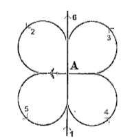
The sequence of the survey flight is carried out sequentially from position 1 to position 6 as shown in Diagram 1:
Diagram 1: Survey Flight Diagram to Determine the Value of the Magnetic Field's Influence Along Various Flight Directions
Article 19. Flight to Determine the Delay of the Recording Measurement Equipment
A flight to determine the delay of the recording measurement equipment is conducted to identify the time delay in the measurement recording of the equipment, aiming to calibrate the measurement data. The flight to determine the delay of the recording measurement equipment must meet the following requirements:
1. The flight location is chosen where there is a typical anomaly (such as an iron bridge or railway track).
2. Flights are conducted sequentially in two opposite directions at the selected location as stipulated in Clause 1 of this Article.
Article 20. Selection of Survey Flight Paths for Testing
1. The survey flight paths for testing shall be selected when meeting the following requirements:
a) Proximity to the survey flight area with not overly complex terrain;
b) Relatively stable magnetic field along the survey flight path;
c) Length of the survey flight path from 15km to 20km.
2. The selection flights to determine the survey test flight paths shall be conducted on days with favorable weather conditions, without geomagnetic storms.
3. The altitude of the selection flights to determine the survey test flight paths shall be equal to the altitude of the regular survey flight paths as stipulated in Clause 5, Article 4 of this Circular.
4. Data processing and selection of survey test flight paths.
Article 21. Measurement of Magnetic Field Variations
1. The work of measuring magnetic field variations shall be carried out according to the national standard TCVN 9427:2012 - Mineral Exploration, Evaluation, and Survey - Magnetic Field Variation Measurement. In cases where magnetic field variation measurements are made for aerial surveys over the sea, they shall be implemented in accordance with the provisions of Clauses 2, 3, and Clause 4 of this Article.
2. The distance from the magnetic field variation measurement station to the survey flight area along the latitude direction shall not exceed 350km.
3. If the size of the survey flight area along the longitude direction is less than or equal to 200km, one magnetic field variation measurement station shall be used. If the size of the survey flight area along the longitude direction exceeds 200km, it shall be carried out as follows:
a) Two magnetic field variation measurement stations shall be set up at the northern and southern ends of the survey flight area;
b) The values of both magnetic field variation measurement stations shall be simultaneously used to calculate the correction factor according to the following formula:
δTbt = δT2 + (V2-V1) x (δT1-δT2)/(V2-V1).
Where:
- δTbt: Average variation value;: Latitude of station 1;
- V (VND/year): is the total investment capital allocated annually for the usable area of social housing for rent, ensuring the preservation of capital, calculated according to the following formula:1 : Latitude of station 2;
- V (VND/year): is the total investment capital allocated annually for the usable area of social housing for rent, ensuring the preservation of capital, calculated according to the following formula:2 : Variation value of station 1;
- δT1 : Variation value of station 2.
- δT2 Article 22. Technical Requirements for Magnetic Survey Flights
1. Magnetic survey flights shall only be conducted when there are no geomagnetic storms.
2. A single flight cycle shall be carried out according to the diagram specified in Clause 2 of this Article, in the following sequence:
a) Departure from the airport;
b) Test flight path;
c) Survey flight paths within the survey area;
d) Test flight path;
e) Return to the airport (end of flight).
Diagram 2: Implementation Diagram for a Single Magnetic Survey Flight

3. Requirements for operators of magnetic survey equipment:
a) Adhere to labor safety and aviation safety regulations as prescribed by law;
b) Regularly monitor the operation status of the equipment and record all flight path information and data in the magnetic survey logbook according to Form 01 issued together with this Circular;
c) Upon completion of the flight, they are responsible for transferring the recorded data from the equipment to the office field department, signing and confirming the flight time in the logbook;
4. For parallel survey flight paths and connecting survey flight paths, continuous flights must be conducted at the same altitude as the regular survey flight paths.
5. Re-flight measurements shall be required if any of the following situations occur:
a) The length of the survey flight path segments exceeds 5km with a deviation greater than one-third (1/3) of the survey flight path length compared to the designed flight path;
b) The measured magnetic field variation value changes by more than 05 nT within a 5-minute period or cannot be recorded;
c) One of the following types of data cannot be recorded: Time, magnetic field value, coordinate value, and real-time GPS time on the aircraft;
d) Parallel survey flight paths and connecting survey flight paths are not continuously flown.
d) The survey flight track for inclined flights, the survey flight track for connected flights shall not be continuously surveyed.
Article 23. Field Office Work
1. Receiving and retaining data and documents from system machine and equipment operators.
2. Checking and evaluating collected data and documents:
a) Constructing actual flight path diagrams.
b) Checking altitude, determining the deviation of the actual flight path from the designed flight path.
c) Statistics on flight paths that do not meet technical requirements and those that need to be flown again according to Clause 5, Article 22 of this Circular.
d) Preliminarily processing measurement data; constructing graphs along the flight path.
đ) Evaluating the error of the flight path measurement carried out according to the formula:
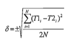
Where:
- δ: Error of the flight path measurement check;
- T1international, T2international: values of the magnetic field strength of the flight path measurement check for the outbound and return trips according to the diagram in Clause 2, Article 22 of this Circular;
- N: number of points for calculating errors.
e) The result of the flight path measurement check error evaluation stipulated in Point đ of this clause must be ≤ 5 nT;
g) Statistics on the length of the flight path measurement.
3. Planning for the next measurement flight.
Article 24. Annual Office Work
1. Calculating the total magnetic field value T at each measurement point of the flight path measurement as follows:
T = TTechnology and Environment on the establishment of the Journal of Standards - δTbt - δTbttk + δTde
Wherein:
a) T: Total magnetic field value at the measurement point adjusted for magnetic variation and calculated based on the map establishment year.
b) TTechnology and Environment on the establishment of the Journal of Standards: Total magnetic field value at the measurement point of the flight path measurement;
c) δTbt: Magnetic variation value at the time of measuring the magnetic field of the flight path measurement calculated according to Clause 2 of this Article;
d) δTbttk : Century variation quantity calculated according to Clause 3 of this Article;
đ) δTde : Value of the influence of the magnetic field direction during the flight measurement calculated according to Clause 4 of this Article.
2. The magnetic variation value δTbt at each measurement point of the flight path measurement is calculated as follows:
δTbt = Tđbt - Ttbn
Where:
a) δTbt : Magnetic variation value at the time of measuring the magnetic field of the flight path measurement;
b) Tđbt: Magnetic field value measured at the magnetic variation station at the same time as the flight path measurement;
c) Ttbn : Average annual magnetic field value at the magnetic variation measurement point (if there is no average annual magnetic field value at the magnetic variation measurement point, then take the average magnetic field value within the measurement period).
3. The century variation value δTbttk is the average of the differences between normal magnetic field values over the years at the same coordinates, calculated as follows:
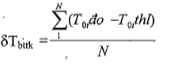
Where:
a) d.1. Amount of taxable income in Vietnam:0iđo and T0ithl: Normal magnetic field value T0 of the year when the flight measurement is conducted and of the year when the map was established at the same coordinate point i.
b) N: Number of values calculated.
4. The value of the magnetic field influence (δTde) in the direction of the flight measurement is calculated as follows:
δTde = Ttb - Ttb_hướng
Where:
a) Itb_hướng: Average magnetic field value in the direction. The average magnetic field value in the direction (Ttb_hướng) is the sum of seven (7) or nine (9) flight measurement data at the central position (A) specified in Clause 3, Article 18 of this Circular;
b) Ttb: Average magnetic field value is calculated as follows:

Data for calculating the correction value of the magnetic field influence in the direction of the flight measurement is the total magnetic field value (T) adjusted for magnetic variation as stipulated in Clause 2 of this Article and corrected for the delay of the recording device as stipulated in this Article; determine the coordinates and measurement point at the central position (A) of the flight measurement area according to the provisions in Clause 3, Article 18 of this Circular.
5. The value of the recording device delay is half (1/2) of the time interval between two extreme values of anomalies when flying through a single anomaly as stipulated in Clause 1, Article 19 of this Circular.
Article 25. Establishment of Magnetic Field Maps
1. Linking magnetic survey flight data: Balance the magnetic survey flight network line using the averaging method as follows:
a) Select the magnetic survey flight line located in the middle of the flight area, crossing through the stable magnetic field zone;
b) Calculate the average deviation value between the intersection points of the magnetic survey flight line and the regular survey flight line according to the formula:
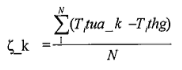
Where:
- ζ_k: Average deviation value of the magnetic survey flight line k;
- Tinternationaltua: Measurement value of the magnetic survey flight line k at the i-th intersection point;
- Tthginternational: Measurement value of the regular survey flight line at the i-th intersection point;
- N is the number of intersection points between the magnetic survey flight line and the regular survey flight line.
The magnetic survey flight line k must be adjusted by the value of - ζ_k nT.
c) Perform linking of the magnetic survey flight line with the regular survey flight line for all magnetic survey flight lines;
d) The deviation value between the magnetic survey flight line k and the regular survey flight line i at the intersection points after the magnetic survey flight line has been balanced is calculated as follows:
Spki = Ttua_kinternational – Tthginternational - ζ_k
For each regular survey flight line, there will be up to k intersection deviation values with the magnetic survey flight line used for linking.
đ) The magnetic field value on the regular survey flight line is linked with the magnetic survey flight line after it has been balanced according to the following formula:
Tthglk = Tthg + f (Spki)
Where:
- Tthglk: Linked regular survey flight line value;
- Tthg: Unlinked regular survey flight line value;
- f (Spki): Is the average value or a linear or quadratic function of the deviation values between the balanced magnetic survey flight line and the regular survey flight line at the intersection points.
2. Evaluating errors in the magnetic field map:
The error in the magnetic field map (m) is determined by the root mean square error between the intersection points of the magnetic survey flight line and the regular survey flight line, calculated as follows:
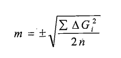
Where:
a) n: Number of intersection points;
b) ∆Tinternational = Tthglk - Ttua;
c) Tthglk: Magnetic field value of the regular survey flight line at the intersection point with the magnetic survey flight line after adjustment according to Article 24 of this Circular and linked according to Clause 1 of this Article;
d) Ttua: Magnetic field value of the magnetic survey flight line at the intersection point with the regular survey flight line after adjustment according to Article 24 of this Circular.
3. Accuracy of the magnetic field map is classified as follows:
a) Low accuracy when m > 15 nT;
b) Medium accuracy when 5 ≤ m ≤ 15 nT;
c) High accuracy when m < 5 nT.
4. Calculation of magnetic anomaly (ΔTa) is performed according to the formula:
ΔTa = Tthglk - T0
Where:
a) Tthglk: Magnetic field value of the regular survey flight line at the intersection point with the magnetic survey flight line after adjustment according to Article 24 of this Circular and linked according to Clause 1 of this Article;
b) T0: Normal magnetic field value at the same measurement point.
Article 26. Products of Magnetic Survey Flight Work
1. Diagrams and magnetic survey flight result maps, including:
a) Actual flight path diagram;
b) Full magnetic field map T (year of establishment);
c) Magnetic anomaly map ΔTa;
d) Graphical magnetic anomaly map ΔTa.
2. Intermediate transformation maps, including:
a) Magnetic field map transformed to poles, equator;
b) First derivative vertical component magnetic field map;
c) Second derivative vertical component magnetic field map;
d) Magnetic field enhancement, reduction map;
đ) Other related intermediate transformation maps.
3. Geological explanation diagrams and maps of magnetic survey flight data, including:
a) Geological structure map based on magnetic survey flight data;
b) Mineral prospect prediction diagram based on magnetic survey flight data.
4. Summary report of magnetic survey flight work.
Article 27. Content of the actual flight path diagram for measurement
1. The actual flight path diagram for measurement prescribed in point a, Clause 1, Article 26 of this Circular shall be constructed on a simplified topographic map at the measurement flight scale; the diagram must clearly display all regular measurement flight paths, supporting measurement flight paths, check measurement flight paths, connecting measurement flight paths, and re-measurement flight paths; the boundary of the designed flight area and the actual flight area; the boundary of areas measured in detail, at different scales, and at different heights.
2. The diagram must detail the name of each measurement flight path and include arrow symbols to indicate the direction of the measurement flight path.
Article 28. Content of the Total Magnetic Field Map T
1. The map is constructed on a simplified topographic map at the measurement flight scale, clearly indicating the year of map creation; it is represented in colors gradually increasing from blue - brown - red corresponding to the magnetic field values from low to high.
2. The difference between magnetic equipotential lines is selected with a value ranging from two (2) to three (3) times the total magnetic field map error.
3. Magnetic equipotential lines are shown in black, with a line width less than 0.3mm. Main magnetic equipotential lines (even 500, 1000) have a line width equal to 1.5 to 2 times that of other equipotential lines; magnetic equipotential lines indicate the magnetic field value (unit nT) and point towards higher magnetic fields.
4. At the extremum points of the magnetic anomaly, the magnetic field value must be recorded, while some magnetic equipotential lines should be omitted.
Article 29. Content of the Magnetic Anomaly Map ΔTa
1. The map is constructed on a simplified topographic map at the measurement flight scale; it is represented in red (for positive magnetic anomalies) or blue (for negative magnetic anomalies); the intensity of the magnetic anomaly is distinguished by the darkness of the color; there must be a color scale legend according to the actual colors on the map.
2. Positive magnetic anomaly equipotential lines are solid lines, with a line width less than 0.3mm. Negative magnetic anomaly equipotential lines are dashed lines, with a line width less than 0.3mm. Equipotential lines where the magnetic anomaly value equals zero (0) are dotted-dashed lines, with a line width less than 0.3mm. Main magnetic anomaly equipotential lines have a difference of ±500nT from the zero line (0), with a line width from 1.5 to 2 times that of other equipotential lines.
3. On the equipotential lines, the magnetic anomaly value (unit nT) is indicated, pointing towards higher magnetic fields.
4. At locations where the magnetic anomaly extremum values are too large or too small, the magnetic anomaly value at the extremum point must be recorded, while some equipotential lines should be omitted.
Article 30. Content of the Magnetic Anomaly Graph Map ΔTa
1. The graph map is constructed on a simplified topographic map at the measurement flight scale; it is represented in red (including both the graph line and the field area) for positive magnetic anomalies ΔT; it is represented in blue (including both the graph line and the field area) for negative magnetic anomalies ΔT.a 2. It fully displays actual measurement flight paths (regular measurement flight paths, supporting measurement flight paths, connecting measurement flight paths, flight path names, measurement flight directions) and the graph of the magnetic anomaly for each measurement flight path.a 3. Notes are included in the map legend and framed marked for areas with strong magnetic anomalies intersecting adjacent continuous graphs; symbols and magnetic field values at extremum points of significant narrow magnetic anomalies are indicated.a if it has negative and positive values, it indicates the red color of the positive anomalous magnetic field value.
2. Fully display the actual survey flight tracks (survey flight track regular, survey flight track inclined, survey flight track connected, name of survey flight track, direction of survey flight) and the graph of the anomalous magnetic field for each survey flight track.
3. Note in the map legend and frame-mark the area with strong anomalous magnetic field intensity that cuts the adjacent continuous graph; indicate symbols, magnetic field values at the points of maximum anomalous magnetic field for narrow but large anomalous magnetic fields.
Article 31. Content of the geological structure map based on airborne magnetic survey data.
1. The geological structure map based on airborne magnetic survey data must fully reflect the results specified in Clauses 2, 3, and Clause 4 of this Article.
2. Results of determining and analyzing faults: display identified faults; delineate geological structural zones.
3. Results of delineating magma blocks. In cases where the formation stages, level of activity, and geodynamic characteristics of the magma block have been determined, they should be detailed according to the level of determination.
4. Results of synthesizing and analyzing physical geological features and geological-physical formations.
Article 32. Content of the mineral prospecting forecast diagram based on airborne magnetic survey data.
The mineral prospecting forecast diagram based on airborne magnetic survey data must fully reflect the following contents: fault system; magnetic anomaly belts; predicted geological structures with mineral prospects; known mineral deposits and ore points in the area; structural zoning results.
Article 33. Summary report on airborne magnetic survey work.
1. The summary report on airborne magnetic survey work includes explanatory notes and accompanying drawings; it must fully reflect the implemented contents, achieved results, products of the project; recommendations and suggestions.
2. The summary report on airborne magnetic survey work must be digitized, stored, and managed in accordance with the provisions of the law on basic geological surveys for minerals.
Chapter IV
GRAVIMETRIC SURVEY WORK
Article 34. Requirements for gravimetric measurement equipment and devices.
1. Gravimeters must be installed synchronously with height measurement devices, GPS navigation positioning systems, including at least three (03) dual-frequency GPS receivers, one (01) mobile GPS receiver mounted on the aircraft, two (02) stationary GPS receivers placed within or near the survey area.
2. There must be a unified data collection control unit ensuring real-time synchronization of all data with GPS and other auxiliary devices. Measurement recording speed ranges from 1 second per data point to 0.1 second per data point; software for processing, calibration, and linking data must be available.
3. Gravimetric measurement equipment must comply with the usage period and conditions stipulated by the manufacturer; technical parameters of the equipment must be checked and ensured to operate normally and meet requirements before installation on the aircraft.
Article 35. Installation of gravimetric measurement equipment on aircraft; selection of aircraft parking positions.
1. The installation of gravimetric measurement equipment on aircraft must be carried out in accordance with the provisions of Clause 1 and Clause 2 of Article 8 of this Circular and the following requirements:
a) Install at the position with the least vibration on the aircraft;
b) After installation, measure the height difference, antenna GPS offset, and gravimeter offset. These parameters will be used during data and gravimetric material processing;
c) Install and start the gravimeter according to the manufacturer's sequence and instructions; operate to determine the background noise of the gravimeter after installation; the measured background noise value must be less than the background noise value according to the manufacturer's guidance.
2. Maintain the operational status of the gravimeter continuously throughout the entire time of airborne magnetic survey work from the beginning until the end of the gravimetric survey.
3. Select aircraft parking positions to ensure appropriate distances from other types of aircraft and transportation means to minimize interference affecting the gravimeter measurement results.
Article 36. Determining Coordinates and Measuring Gravity from the National Gravity Benchmark to the Aircraft Parking Position
1. Positioning coordinates, altitude of the aircraft parking position, and measuring the connection with the national gravity benchmark to determine the gravity value at the aircraft parking position. The measurement principle follows a cycle from the national gravity benchmark to the aircraft parking position and vice versa.
2. Entering coordinates, altitude, and gravity value at the aircraft parking position into the gravity meter to serve as the basis for determining the gravity field during the flight measurement process.
Article 37. General Survey Flight Over the Entire Flight Region
1. Each gravity measurement project and task must conduct at least one general survey flight over the entire flight region to determine the general boundaries of the flight region, terrain conditions, and objects serving the planning and organizing of safe and effective flights.
2. The altitude of the general survey flight over the entire flight region shall not be lower than the altitude of the gravity measurement flight along the designed route.
Article 38. Flight Testing of the Gravity Meter
1. Conduct flight testing of the relative height meter at altitudes of 200m, 400m, 600m, 800m, and 1000m.
2. Requirements for the flight test route (standard route) of the gravity meter:
a) The flight test route of the gravity meter must determine the coordinates of the start and end points of the route; the length must be between 30km and 40km.
b) It should be selected in areas with non-complex terrain; the gravity field value of the flight test route must have a difference range of 10mGal to 20mGal.
c) The gravity field of the flight test route must be measured in detail on the ground.
3. Technical requirements for flight testing of the gravity meter, data processing, and calculation of measurement errors:
a) Conduct a minimum of ten (10) flight passes at the test route altitude and speed within the limits specified by the manufacturer;
b) Process the measurement data;
c) The mean square error (δ) of the flight measurement results compared to the ground measurement values of the flight test route is calculated as follows:
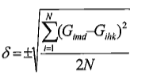
Where:
: bid price after corrections and adjustments, minus any discount (if applicable) of the lowest bidder among those detailed financial evaluations;internationalmđ : The gravity field value measured on the ground at point i;
: bid price after corrections and adjustments, minus any discount (if applicable) of the lowest bidder among those detailed financial evaluations;internationalhk : The gravity field value measured by the flight test route at point i;
- N: Number of points for error calculation.
The mean square error of the flight measurement results compared to the ground measurement values on the flight test route ≤ 0.65 mGal.
Article 39. Preparations Before Each Gravity Measurement Flight
1. Check the technical parameters of the gravity meter to ensure that all parameters meet technical requirements or the manufacturer's requirements.
2. Inspect the entire system of equipment of the gravity meter to ensure normal operation.
3. Measure the "0" point shift:
a) Before and after completing the measurement flight, record gravity data to determine the "0" point shift during continuous recording for 20 to 30 minutes;
b) During the measurement of the "0" point shift, stop all activities affecting or causing vibrations to the aircraft.
Article 40. Selection and Determination of the Flight Test Route
1. The survey flight paths for testing shall be selected when meeting the following requirements:
a) Proximity to the survey flight area with not overly complex terrain;
b) The gravity field of the flight test route is relatively stable;
c) Length of the survey flight path from 15km to 20km.
2. The selection and determination of the flight test route are carried out on days with favorable weather conditions.
3. The altitude of the flight test route selection is the same as the altitude of the gravity measurement flight route as stipulated in Clause 5, Article 4 of this Circular.
4. Data processing and selection of survey test flight paths.
Article 41. Technical Requirements for Gravity Measurement Flights
1. The flight cycle for conducting a gravity measurement trip is specified in Diagram 3 of this clause and proceeds as follows: as specified in Figure 3 of this Clause as follows:
b) Test flight path;
c) Survey flight paths within the survey area;
d) Test flight path;
e) Return to the airport (end of flight).
Diagram 2: Implementation Diagram for a Single Magnetic Survey Flight

Diagram 3: Scheme for Conducting a Gravity Measurement Flight
2. Requirements for the operator of the gravity measurement system and equipment:
b) Regularly monitor the operation status of the equipment and record all flight path information and data in the magnetic survey logbook according to Form 01 issued together with this Circular;
c) Upon completion of the flight, they are responsible for transferring the recorded data from the equipment to the office field department, signing and confirming the flight time in the logbook;
c) Upon completion of the flight, the operator shall be responsible for transferring data from the measuring machines and equipment to the field office department, signing off on the flight time in the flight logbook.
3. For flights along profile lines and connecting lines, continuous measurements must be conducted at the same altitude as regular measurement flights.
4. A re-measurement must be conducted if any of the following situations occur:
b) The measured magnetic field variation value changes by more than 05 nT within a 5-minute period or cannot be recorded;
b) Failure to record any of the following types of data: Time, gravity field value, coordinate value, and real-time GPS time on the aircraft;
c) The measured value of the "zero" point shift before and after the flight exceeds the allowable value set by the manufacturer of the airborne gravity meter;
d) Profile lines and connecting lines are not continuously measured.
Article 42. Field Office Work
1. Receiving and storing gravity data and documents from the operator of the measuring system and equipment.
2. Checking and evaluating collected data and documents:
a) Constructing a map of the actual flight path;
b) Checking altitude and determining the deviation of the actual flight path from the design;
c) Statistics on flight paths that do not meet technical requirements and those that need to be flown again according to Clause 5, Article 22 of this Circular.
3. Calculating gravity corrections:
a) The correction for the "zero" point shift is determined as follows:
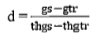
Where:
- d: Shift value mGal/h;
- thgtr: Pre-flight measurement time;
- thgCLASS MONOCOTYLEDON: Post-flight measurement time;
- gtr: Pre-flight gravity measurement value;
- gCLASS MONOCOTYLEDON : Post-flight gravity measurement value.
b) The correction for the effect of aircraft motion (Eotvot) on the measurement result is calculated as follows:
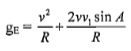
Where:
- v: Aircraft speed;
- A: Direction of the measurement flight path;
- v1= ωRcos θ: Earth's rotational speed, θ: Latitude;
- ω= 2π/86164: Earth's angular velocity;
- R: Earth's radius;
c) The height anomaly (Fair) is calculated as follows:
Δgfa= gđ + gfa - g0
Where:
- Δgfa: Fair anomaly value;
- gđ : Eotvot-corrected measurement value;
- gfa : Fair correction value, gfa = 0.3086 × h (mGal), where h is the aircraft's height above the ellipsoid surface in meters;
- g0: Normal gravity value calculated as follows: g0 = 978032.53359 × (1 + 0.0053024x sin2B - 0.0000058 × sin2 ²B) (mGal); B: Latitude of the measurement point.
4. Evaluating errors on the check flight path is calculated as follows:
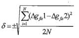
Where:
- Δgfa1 and Δgfa2: Fair anomaly values of the check flight path on the outbound and return trips according to the scheme specified in Diagram 3, Clause 1, Article 41 of this Circular;
- N: Number of points for error calculation;
- Error on the check route ≤ ± 0.65 mGal.
5. Statistics on the length of the gravity measurement flight path and anomalies detected.
6. Planning for the next flight.
Article 43. Annual Office Work
1. Calculate the intermediate layer anomaly value (Bughe anomaly) using the following formula:
ΔgB= gđ + gfa + gB – gec+ gorganize credit institutions, foreign bank branches are responsible for organizing the implementation of this Circular. – g0
Where:
a) ΔgB: Bughe anomaly value;
b) gđ : Eotvot-corrected measurement value as stipulated in Point b, Clause 3, Article 42 of this Circular;
c) gfa: Fair correction value, gfa = 0.3086 × h (mGal), where h is the aircraft's height above the ellipsoid surface in meters;
d) gB: Bughe correction value implemented as stipulated in Clause 2 of this Article;
đ) gorganize credit institutions, foreign bank branches are responsible for organizing the implementation of this Circular.: Terrain correction value implemented as stipulated in Clause 3 of this Article;
g) gce: Earth curvature correction value as stipulated in Clause 4 of this Article;
h) g0: Normal gravity value.
2. Calculate the Bughe correction value, unit of measurement is mGal:
a) Bughe correction when flying over land is calculated using the formula:
gB= 2πGρh = 0.04192 × ρ × h
b) Bughe correction when flying over sea is calculated using the formula:
gB= 0.04192 × (ρ-ρnb) × H
Where:
- H: Depth of the seabed at the projection point of the aircraft on the sea surface in meters;
- ρ: Average density of the intermediate layer is 2.67 g/cm³, in specific cases depending on geological conditions, the actual average density of the intermediate layer may be used;3- ρ
: Average density of seawater is 1.03 g/cm³.nb3. Calculate terrain influence correction:3.
a) Using an appropriate correction method clearly stated in the approved gravity measurement flight plan;
b) Terrain correction is carried out based on topographic maps or digital elevation model (DEM) data at a scale that meets accuracy requirements;
c) Using the average density of the intermediate layer when calculating the Bughe anomaly to calculate the terrain influence correction.
4. Earth curvature correction is calculated as follows:
a) h: Height above sea level in kilometers.

Where:
b) ρ: Actual density of the intermediate layer.
5. Linking gravity measurement documents: The linking of gravity measurement documents is based on the network of profile lines within the measurement area. The method of linking gravity measurement documents is similar to the method of linking flight data as stipulated in Clause 1, Article 25 of this Circular.
5. Linking gravity survey data: The linking of gravity survey data relies on the network of inclined survey flight tracks within the survey area. The method of linking gravity survey data is carried out similarly to the method of linking magnetic survey data as prescribed in Clause 1, Article 25 of this Circular.
Article 44. Annual Office Work
1. Content of work:
a) Statistics and systematization of original documents already implemented for the project;
b) Evaluate the error of the gravity field map (m) as stipulated in Clause 2 of this Article;
c) Process, analyze, and interpret geological data based on gravity materials;
d) Write a summary report.
2. Evaluation of the error of the gravity field map (m):
The error of the gravity field map is determined by the root mean square error between the intersection points of the survey flight lines and the regular flight lines, calculated as follows:
Where:
a) n: Number of intersection points;
b) ∆Ginternational = g_thglk – g_tua;
c) g_thglk: The value of the gravity field of the regular flight line at the intersection point with the survey flight line after adjustment according to Clause 3 of Article 42, Clauses 1, 2, and 3 of Article 43, and linked according to Clause 5 of Article 43 of this Circular;
d) g_tua: The value of the gravity field of the survey flight line at the intersection point with the regular flight line after adjustment according to Clause 3 of Article 42, Clauses 1, 2, and 3 of Article 43 of this Circular;
3. Accuracy of the gravity field map is classified as follows:
a) Low accuracy when m > 5mGal;
b) Medium accuracy when 1 ≤ m ≤ 5 mGal;
c) High accuracy when m < 1 mGal.
Article 45. Products of the aerial gravity survey work
1. Gravity field maps, including:
a) Actual flight path diagram;
b) Fair anomaly map;
c) Bouguer anomaly map.
2. Intermediate transformation maps, including:
a) First derivative map of vertical component;
b) Second derivative map of vertical component;
c) Gradient map of horizontal component;
d) Map of gravity field enhancement and reduction.
đ) Other related intermediate transformation maps.
3. Geological explanation maps based on aerial gravity survey data, including:
a) Geological structure map based on gravity data;
b) Mineral prospect prediction diagram based on aerial gravity survey data;
c) Deep Earth crust structure diagram based on aerial gravity survey data;
4. Summary report of the aerial gravity survey work.
Article 46. Content of the actual flight line diagram
The actual flight line diagram for the aerial gravity survey specified in Point a Clause 1 of Article 45 of this Circular is constructed similarly to the actual flight line diagram from the provisions of Article 27 of this Circular.
Article 47. Content of the geological structure map based on aerial gravity survey data
1. The geological structure map based on aerial gravity survey data must fully reflect the results as stipulated in Clauses 2, 3, and 4 of this Article.
2. Results of determining and analyzing faults: display identified faults; delineate geological structural zones.
3. Results of delineating magma blocks. In cases where the formation stages, level of activity, and geodynamic characteristics of the magma block have been determined, they should be detailed according to the level of determination.
4. Results of synthesizing and analyzing physical geological features and geological-physical formations.
Article 48. Content of the mineral prospect prediction diagram based on aerial gravity survey data
The mineral prospect prediction diagram based on aerial gravity survey data must fully reflect the following contents: Fracture system; gravity anomaly zones; predicted geological structures with mineral prospects; known mineral deposits and ore points in the area; structural zoning results.
Article 49. Content of the deep Earth crust structure diagram
The deep Earth crust structure diagram established thereon must reflect the following contents:
1. Geological structural units divided according to different scales and depths of development into structural levels such as regions, areas, blocks, and structural zones.
2. Morphology of crystalline basement surfaces.
3. Deep fracture systems identified through gravity data.
4. Intrusive magma bodies identified through gravity data.
Article 50. Summary Report of Aerial Gravity Survey Work
1. The summary report of aerial gravity survey work includes explanatory text and accompanying drawings; it must fully reflect the completed content, achieved results, products of the project; recommendations and suggestions.
2. The summary report of aerial gravity survey work must be digitized, stored, and managed according to the laws on basic geological surveys for minerals.
Chapter V
Article 30. IMPLEMENTATION AND ORGANIZATION OF IMPLEMENTATION
Article 51. Effective Date
1. This Circular shall take effect from February 15, 2019.
2. Provisions related to aerial gravity measurement work serving geological work and mineral exploration as stipulated in Circular No. 08/2012/TT-BTNMT dated August 8, 2012, of the Minister of Natural Resources and Environment regarding detailed gravity measurements cease to be effective from the date this Circular takes effect.
Article 52. Implementation Organization
1. The ministries, ministerial-level agencies, agencies under the Government, provincial People's Committees, centrally governed cities, and related organizations and individuals shall be responsible for implementing this Circular.
2. The Director of the Vietnam General Department of Geology and Mineral Resources shall be responsible for guiding, monitoring, and inspecting the implementation of this Circular./.
|
Place of Receipt: |
DEPUTY MINISTER DEPUTY MINISTER (Signed) Tran Quy Kien |
Original document (PDF)
Download
Relations map
Click a document to open. A red border = a relation that changes validity.
Translations
This document is available in the following languages: