
This Circular sets forth technical requirements for direct topographic surveying to serve the creation of topographic maps and geographic base databases at scales of 1:500, 1:1000, 1:2000, and 1:5000. It provides detailed regulations on survey methods, techniques, accuracy, data processing procedures, and control network adjustment.
적용 범위
State management agencies for surveying and mapping, organizations, and individuals participating in implementing projects, tasks related to surveying and mapping activities, and building geographic base databases using direct surveying methods or combined with other methods.
핵심 사항
- State management agencies for surveying and mapping and organizations, and individuals participating in implementing projects related to surveying and mapping activities, and building geographic base databases must apply direct surveying methods as prescribed.
- The accuracy of the first-level control network does not exceed ±0.02m for the weakest point position and ±0.03m for the weakest point elevation.
- The control network is established from national coordinate and elevation points, divided into multiple levels to ensure necessary accuracy.
- Direct surveying methods using static or dynamic GNSS technology must comply with regulations regarding satellite signal reception time and specified errors.
- After completing the surveying work, results are processed and calculated for network adjustment according to the principle of least squares.
🌐 이 문서의 사회적 영향
- Positive impacts include ensuring high accuracy during topographic surveying, thereby improving the quality of maps and geographic base databases.
- Negative impacts may include significant investment costs for GNSS technology equipment and longer project implementation times.
❓ 자주 묻는 질문
What technology is used for direct surveying?
Static GNSS, dynamic GNSS, post-processing kinematic GNSS (PPK GNSS) technology, and geometric leveling or trigonometric height measurement technology.
What is the accuracy of the first-level control network?
The root mean square error of the weakest point position does not exceed ±0.02m; the root mean square error of the weakest point elevation does not exceed ±0.03m.
What is the common satellite signal reception time for two receivers on one edge when using static GNSS technology?
Not less than 45 minutes for single-frequency receivers and 30 minutes for dual-frequency or higher receivers.
In which scope are direct surveying methods applied?
The scope includes small areas requiring high-precision surveying.
After completing the surveying work, how is the data processing procedure carried out?
Survey results are processed and calculated for network adjustment according to the principle of least squares.
전문
CIRCULAR
Technical Regulations for Direct Topographic Surveying to Serve the Creation of Topographic Maps and Geographic Base Databases at Scales of 1:500, 1:1000, 1:2000, and 1:5000
Pursuant to Decree No. 21/2013/NĐ-CP dated March 4, 2013, promulgated by the Government, stipulating the functions, tasks, powers, and organizational structure of the Ministry of Natural Resources and Environment;
Pursuant to Decree No. 45/2015/NĐ-CP dated May 6, 2015 of the Government on surveying and mapping activities;
At the proposal of the Director of the Vietnam National Survey and Mapping Agency, the Head of the Science and Technology Department, and the Head of the Legal Affairs Department;
The Minister of Natural Resources and EnvironmentngThe Minister of Natural Resources and Environment hereby issues this Circular on Technical Regulations for Direct Topographic Surveying to Serve the Creation of Topographic Maps and Geographic Base Databases at Scales of 1:500, 1:1000, 1:2000, and 1:5000. reason ratios of 1:500, 1:1000, 1:2000, 1:5000.
PART I
GENERAL PROVISIONS
Article 1. Scope of Regulation
This Circular stipulates technical requirements for direct topographic surveying work to serve the creation of topographic maps and geographic base databases at scales of 1:500, 1:1000, 1:2000, and 1:5000.
Article 2. Applicability
This Circular applies to state management agencies for surveying and mapping, organizations, and individuals participating in implementing projects, tasks, and production activities in the field of map drawing and building geographic base databases using direct surveying methods or other surveying methods that incorporate direct topographic surveying.
Article 3. Explanation of Terms
In this Circular, the following terms shall be understood as follows:
1. National coordinate grid is a unified control grid for coordinates nationwide serving topographic map drawing, cadastral map drawing, establishment of geographic base databases, and various thematic maps, as well as scientific research. The national coordinate grid includes the level 0 grid, level I, II, and III grids.
2. National height grid is a unified control grid for heights nationwide measured by geometric leveling methods, serving the determination of heights for topographic map drawing and scientific research. The national height grid includes levels I, II, III, and IV.
3. Basic control grid is a control grid for coordinates and heights developed from the national coordinate and height grids to establish control grids for detailed surveying and mapping in a specific area.
4. Surveying control grid is a control grid for coordinates and heights developed from the basic control grid or higher-level grids to serve detailed surveying in the survey area.
5. GNSS technology is positioning and navigation technology using a global satellite system (Global Navigation Satellite System - GNSS).
6. Static GNSS measurement technology is a relative positioning method using two or more GNSS signal receivers fixed at two or more points to be measured to collect Code (Coarse/Acquisition Code) and Phase (Carrier phase) measurements from satellites over a sufficient period of time to establish geodetic control grids.
7. Kinematic GNSS measurement technology is a method similar to static GNSS measurement with one receiver fixed (Base station) and one or more mobile receivers (Rover stations). After performing initial measurement techniques at the fixed station, the mobile receiver approaches the points to be measured, collects satellite signals within a very short time (a few measurements) but still achieves centimeter-level accuracy in coordinates and heights.
8. Real-time Kinematic GNSS measurement technology is a method where data is processed and coordinates are calculated in the local coordinate system immediately on-site.
9. Post-processing Kinematic GNSS measurement technology is a method where the coordinates and heights in the local coordinate system of the measurement point are calculated after processing the measurement data in the office.
10. Electronic total station is a device integrating angle and distance measurement functions, with measurement data automatically read, displayed on a screen, and recorded as a data file within the same device.
11. Electronic level is a device measuring height differences using a geometric leveling method but employing a barcode pair, allowing automatic reading of the scale, recorded as a data file.
12. Geoid model is a set of data representing the spatial position of the geopotential zero surface (W0) relative to the reference ellipsoid in the Earth's reference frame. The Geoid model is used to determine orthometric heights of points when measuring with GNSS technology.
Article 4. General Provisions on Direct Measurement Methods
1. The direct terrain measurement method shall be applied to small areas that require high accuracy mapping. The results of the measurements shall be recorded in numerical form or on paper suitable for creating digital topographic maps and building geographic database foundations.
2. The direct terrain measurement method uses specialized measuring equipment to directly approach the measurement points to collect necessary parameters to determine the coordinates and elevations of the points to be measured from the coordinates and elevations of control grid points.
3. Before mapping, a site survey must be conducted, data collected, and a project, technical design estimate, technical outline, and economic and technical justification (hereinafter collectively referred to as technical design) prepared. The technical design must cover all geodetic work in the measurement area or each stage thereof, including individual items of work, and must be approved by the competent authority before construction begins.
4. Measuring instruments and equipment used must be inspected, tested, and calibrated according to the provisions in Chapter VI of this Circular.
5. Quality inspection work must be carried out regularly, strictly, and promptly from the start of construction until completion.
Chapter II
MATHEMATICAL BASIS AND ACCURACY
Article 5. Coordinate and Elevation Systems
1. Coordinates of control grid points and detailed measurement points in direct terrain measurement shall be measured and calculated from national coordinate origin points of Class "0", Class I, II, and III within the VN2000 coordinate system, zone 3° projection, with specific central meridians defined in the technical design.
2. Elevations of control grid points and detailed measurement points in direct terrain measurement shall be measured and calculated from national elevation origin points of Class I, II, III, and IV.
Article 6. Representation of Topography
1. Basic contour intervals prescribed for different terrain slope conditions and map scales are set forth in Table 1:
|
Slope |
Basic Contour Intervals (m) for Various Map Scales |
|||
|
1:500 |
1:1000 |
1:2000 |
1:5000 |
|
|
Plain Areas with Slope Less Than 2° |
0,25 0,5 |
0,25 0,5 |
0,5 1,0 |
0,5 1,0 |
|
Low Hill Areas with Slope from 2° to 6° |
0,5 |
0,5 1,0 |
0,5 1,0 2,5 |
1,0 2,5 |
|
Areas with Slope from 6° to 15° |
1,0 |
1,0 |
2,5 |
2,5 5,0 |
|
Areas with Slope Greater Than 15° |
1,0 |
1,0 |
2,5 |
2,5 5,0 |
2. Special contour interval regulations may be applied based on specific project requirements, suitable for the purpose of the project.
3. Within a measurement area, only one basic contour interval should be used to represent topography. In special cases, two basic contour intervals may be used, but this must be specified in the technical design.
4. When basic contours fail to adequately depict the characteristics of the terrain suitable for the intended use or when the distance between two basic contours exceeds 2.5 cm on the map scale, half and quarter basic contour intervals shall be used in combination with increased density of height annotation points at characteristic locations to clearly represent the terrain.
5. The number of height annotation points (including both characteristic points and evenly distributed height points) in 1dm² on a topographic map shall not be less than 10 points. In flat areas where contour lines cannot be drawn, the density of height points on the map shall not be less than 25 points in 1dm².
Article 7. Control Grid
1. The coordinate and elevation control grids serving direct terrain measurement are developed from national coordinate and elevation origin points and are divided into two levels:
a) Basic control grid;
b) Mapping control grid.
2. The basic control grid includes coordinate and elevation control grids, divided as follows:
a) For coordinates, it is divided into two levels: Level 1 Basic Grid; Level 2 Basic Grid.
b) For elevations, there is one level called Technical Elevation Grid.
3. The mapping control grid is divided into two levels of common coordinate and elevation grids:
a) Level 1 Mapping Grid;
b) Level 2 Mapping Grid.
4. The control grid for direct terrain measurement is constructed following the principle of progressing from higher to lower levels, from overall to local. If GNSS technology is used, intermediate levels can be bypassed when constructing lower-level coordinate grids.
5. In cases of special technical requirements, a separate control network or free coordinate grid meeting the required accuracy, ensuring point density, and suitable for the specific mapping process may be established and must be clearly stated in the technical design.
6. The density of geodetic control points depends on the mapping scale, basic contour intervals, and other geodetic work requirements at all stages of investigation, construction, and operation of projects.
7. The average density of national geodetic points must ensure at least one coordinate point in every 20 to 30 km² and one elevation point in every 10 to 20 km² for mapping at a scale of 1:5000. For mapping at scales of 1:2000, 1:1000, and 1:500, one coordinate point in every 5 to 15 km² and one elevation point in every 5 to 10 km² are required. If including points from the basic control grid, the point density must ensure at least:
a) Urban and industrial zones: 4 points per km²;
b) Unconstructed areas: 1 point per km²;
c) Areas without subsequent geodetic work depend on the mapping method to determine the density of geodetic control points.
8. The mean error in determining the position of the final level control points on the plane of the control grid is ±0.1 mm on the map scale required to be established, and in difficult areas with terrain slope >15°, it is ±0.2 mm on the map scale.
9. The mean error in determining the position of the final level control points for elevation does not exceed 1/10 of the basic contour interval in plain areas and 1/6 of the basic contour interval in areas with terrain slope >15°.
10. The mean error in determining the position of the final level control points on the plane of the control grid after adjustment shall not exceed twice the mean error in determining the position of the nearest higher-level geodetic control points, and in difficult areas with terrain slope >15°, it shall not exceed twice.
Article 8. Provisions on the accuracy of cadastral and topographic elements
1. The mean error for determining the planimetric position of fixed, distinct land features relative to the nearest control point shall not exceed ±0.3mm on the map scale, while for indistinct land features it shall not exceed 0.5mm on the map scale. In cities and industrial zones, the mutual mean error between fixed, important land features shall not exceed ±0.3mm on the map scale.
2. The mean error for topographic surveying relative to the final elevation control point, based on the basic uniform height interval, shall not exceed the provisions set out in Table 2. The height error of characteristic topographic points shall not exceed one-third of the basic uniform height interval.
|
Slope |
Mean errors for terrain contour surveys (basic uniform height intervals) for various map scales |
|||
|
1:500 |
1:1000 |
1:2000 |
1:5000 |
|
|
From 0° to 2° |
1/4 |
1/4 |
1/4 |
1/4 |
|
From 2° to 6° |
1/3 |
1/3 |
1/3 |
1/3 |
|
From 6° to 15° |
1/3 |
1/3 |
1/2 |
1/2 |
|
Over 15° |
1/2 |
1/2 |
1/2 |
|
Note: When surveying the basic uniform height interval of 0.25m, the above error shall not exceed one-third of the basic uniform height interval.
3. Based on the value of the planimetric and height differences of land features on the map compared to the verification results, the accuracy of the map is evaluated. The permissible difference value shall not exceed twice the mean error mentioned above. The number of points with large errors (70% to 100% of the permissible value) shall not exceed 5% of the total number of verification points. In all cases, errors shall not be systematic.
Chapter III
ESTABLISHMENT OF CONTROL NETWORKS
Article 9. Technology for measuring the control network
Level 1 base networks are measured using static GNSS technology; level 2 base networks and level 1 mapping networks may apply angle-side traverse methods or static GNSS technology; level 2 mapping networks may apply angle-side traverse methods, intersection methods, static GNSS technology, or dynamic GNSS measurement techniques.
Article 10. Level 1 Base Network
1. The level 1 base network is developed from national coordinate system origin points.
2. The distance between points in the level 1 base network ranges from 1 to 5 km depending on the shape of the survey area and the terrain conditions.
3. The level 1 base network is designed as a dense triangular grid, chain of triangles, and quadrilateral chains covering the entire survey area. The level 1 base network must be connected to at least three national coordinate system origin points located at control positions and evenly distributed throughout the network. The level 1 base network is designed on existing topographic maps in the survey area, with smaller scales that are closest to the survey scale.
4. The location of points in the level 1 base network must be chosen in areas with stable, solid ground, conducive to satellite signal reception, with an unobstructed sky view angle of no less than 150°. In special cases, the sky view angle must not be less than 120° and only partial obstruction from one direction is allowed. The point location must be at least 500m away from radio stations and at least 50m away from objects capable of interfering with satellite signals such as high-voltage power lines, metal roofs...
5. If the survey area is designed to increase the density of lower-level control networks in the form of angle-side traverses, the location of points in the level 1 base network must be selected to form pairs of horizontal lines or horizontal lines with higher-level points to develop level 2 base networks in the form of angle-side traverses.
6. Points in the level 1 base network must be marked with concrete monuments, equipped with marker centers, buried underground or attached to rock or structures. The numbering rules for points must be specified in the technical design. If long-term protective walls are required, they must be specified in the technical design. Monument specifications and wall specifications comply with the provisions in Appendix 1 of this Circular.
7. Monuments belonging to the level 1 base network must have a monument location diagram. The specifications for the monument location diagram comply with the provisions in Appendix 2 of this Circular.
Article 11. Primary Control Network Survey
1. The primary control network is measured using static GNSS technology. The satellite signal receiver used for measuring the primary control network is a type that measures both Code and Phase values, either single-frequency or multi-frequency, with a specified measurement edge error ≤10mm+1mm.D (D is the length of the edge being measured, in kilometers). The common satellite signal reception time for two receivers on one edge must be no less than 90 minutes for single-frequency receivers and 60 minutes for dual-frequency or higher receivers.
2. The minimum number of satellites during measurement is 4; the maximum PDOP value is 4; the satellite signal reception interval (Epoch) of the receivers must be the same value (typically using 15 seconds, 5 seconds, or 1 second); the signal reception angle threshold is 15°.
3. When using a single-frequency satellite signal receiver, the measurement edge length must not exceed 15km. There is no limit to the distance measured with dual-frequency or higher receivers. In special cases where the measurement edge is much longer than the average edge length of the network, the measurement time must be increased by 20 minutes for each additional 10km beyond the average edge length.
4. The antenna of the satellite signal receiver must be placed firmly and accurately centered on the marker with an allowable error ≤ 2mm; the antenna height must be measured twice before and after the measurement session using a steel tape measure, reading to the millimeter.
5. Measurement station parameters must be accurately collected and recorded in the field GNSS measurement logbook, including: date of measurement, time of measurement, machine number, point identifier, antenna type, antenna measurement method, measurement point layout diagram, weather conditions, measurer, and other special information if applicable. Detailed specifications for GNSS measurements comply with the provisions in Appendix 3 of this Circular.
6. The measurement data file name depends on the type of satellite signal receiver but must include basic information such as the point identifier, day of the year, and session number within the day. Raw measurement data must be organized and stored on computers clearly, completely, securely, and conveniently for exploitation and review at various levels.
7. After completing the field measurement of the primary control network, the following measurement data, logs, and related documents must be submitted:
a) GNSS measurement data for calculation and storage;
b) Field GNSS measurement logbook;
c) A compiled measurement data summary table printed on paper and in digital form (according to the format of Microsoft Office Excel software);
d) A construction layout diagram of the coordinate measurement network printed on paper and in digital form (according to graphic file formats *.dgn, *.dxf, *.dwg) clearly distinguishing between different measurement sessions.
Article 12. Data Processing, Calculation, and Adjustment of the Primary Control Network
1. Data processing and adjustment of the primary control network must be performed using officially licensed software from GNSS equipment manufacturers worldwide. Careful study of the software's user guide and particular attention to the manufacturer's recommendations for specific situations when processing measurements must be conducted.
2. The processing of primary control network measurement data must be carried out using the relative processing method for each measurement edge with simultaneous data from two satellite signal receivers as follows:
a) Before preliminary processing of edges, all measurement data and logs must be thoroughly checked, verifying the consistency between point names, antenna types, antenna measurement methods, antenna heights, and measurement times;
b) The maximum number of GNSS measurement values in data files should be utilized during calculations. Arbitrary removal of measurement values is not allowed unless the technical criteria accepted by the software are still met. In special cases, up to 25% of the total GNSS measurement values can be removed, including partial or complete removal of data from one or more satellites, limiting the time period, increasing the signal rejection angle for low-elevation satellites but not exceeding 20°;
c) In all cases, processed edges must have integer solutions (Fixed) and meet the technical criteria set by the processing software;
d) It is permissible to remove some edges after preliminary processing if they do not meet the reliability criteria specified by the software. Removed edges must not disrupt the network's connectivity;
đ) After preliminary edge processing, a check of the network's closure errors and geodetic height closure must be conducted through the coordinates ΔX, ΔY, ΔZ and geodetic height difference ΔH of the edges after processing, as stipulated in Table 3 below:
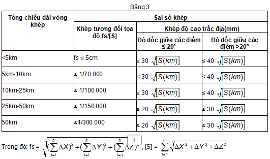
The values of ΔX, ΔY, ΔZ are obtained from solving the edges participating in the closure loop.
3. Network adjustment of the primary control network can only be performed after preliminary edge processing and checking the closure errors for the entire network within the tolerance limits. If any criterion exceeds the tolerance limit or the closure result does not meet the requirements as specified in Table 3 of this Circular, weak edges must be identified, reprocessed, replaced, or removed. The number of edges that can be removed cannot exceed 2% of the total number of edges in the network and must be clearly stated in the technical report.
4. An initial adjustment must be performed by determining the coordinates and heights of all points in the network based on one origin point for coordinates and one origin point for height in the central area of the network. The coordinates and heights obtained after the initial adjustment at the remaining origin points must be compared with the original coordinates and heights of those points to identify any abnormal differences.
5. If abnormal differences in coordinates and heights are detected during the initial adjustment, the following steps must be taken until the cause is determined:
a) Recheck and verify the accuracy of the original data;
b) Replace the origin point used for initialization with another origin point;
c) Establish new loops passing through the origin point used for initialization and points with large differences;
d) Reprocess the relevant edges in the network;
đ) Reinspect the actual condition of the origin points in the field to avoid cases of markers being displaced or misidentified.
e) In special cases, when the measures above have been implemented but the requirements are not met, the original point may be removed during grid adjustment if the remaining original points in the grid still satisfy the minimum number requirement stipulated and must be clearly stated in the technical report;
g) The formal adjustment process shall only be carried out once all issues identified during the preliminary adjustment process have been thoroughly resolved.
6. The primary control grid is adjusted in the VN-2000 coordinate system, zone 3°, using national coordinate points as the original points.
Article 13. Processing of Benchmark Heights for Points in the Primary Control Grid
1. The benchmark heights of points in the primary control grid can be determined through geometric leveling methods or static GNSS height measurements. If the static GNSS method is used to measure both height and coordinates simultaneously, the benchmark heights of the primary control grid points are calculated from the geodetic height determined by combining static GNSS measurements with the Geoid model and height original points according to the formula:
h = H - N Where: - h: is the benchmark height; - H: is the geodetic height measured by GNSS technology; - N: is the value determined from the Geoid model.
2. Depending on the Geoid model used, the benchmark heights will achieve different levels of accuracy. The highest accuracy Geoid model available in the region provided by the State Management Agency for Surveying and Mapping of Vietnam must be utilized. The benchmark heights of points in the grid will achieve technical grade accuracy if the grid is connected to three or more Grade IV or higher height original points and uses the global Geoid model EGM2008 or a local Geoid model with appropriate accuracy published by the State Management Agency for Surveying and Mapping of Vietnam.
3. Local Geoid models covering the survey area may be constructed for height transfer when using GNSS technology. The accuracy of this Geoid model must be clearly stated in the technical design.
Article 14. Accuracy of the Primary Control Grid, Report on Adjustment Results
1. The accuracy of the primary control grid after adjustment is specified as follows:
a) The mean error of the weakest point position does not exceed: ±0,02m;
b) The mean error of the weakest geodetic height does not exceed: ±0,03m;
c) The relative mean error of the weakest edge: ≤ 1:100,000;
d) The mean error of the azimuth angle does not exceed: ±5";
2. The report on the adjustment results of the primary control grid may use templates of reports (Reports) from GNSS processing software or be compiled and organized into information groups:
a) Basic parameters of the grid;
b) Edge processing results;
c) Closure errors;
d) Adjustment results for edge lengths, azimuths, and height differences;
đ) Adjustment results for coordinates and heights.
3. After completing the measurement, calculation, and adjustment of the primary control grid, the following data must be submitted:
a) GNSS data files for calculation and storage;
b) Field GNSS measurement book;
c) Measurement data compilation sheets for each session, printed on paper and in digital format (in the format of Microsoft Office Excel);
d) On-site construction diagram for the coordinate grid measurement, printed on paper and in digital format (in the format of graphic file *.dgn or *.dxf, *.dwg);
đ) Report on the adjustment results of the primary control grid.
Article 15. Secondary Control Network
1. The secondary control network is established with the purpose of increasing control points for the construction of primary surveying networks, secondary surveying networks, and for directly detailed surveying throughout the entire survey area.
2. The secondary control network is permitted to apply the traverse angle measurement method, edge measurement, or static GNSS technology. The network is developed from coordinate origin points belonging to the primary control network upwards.
3. The accuracy of the secondary control network, primary surveying network, and secondary surveying network depends on the map scale or the foundation geographic database that needs to be established. If there are areas within the survey zone requiring mapping at different scales, then the control networks related to the largest scale mapping area must be set up with technical standards corresponding to the largest scale mapping.
4. Regulations on the coordinate closure error, the weakest point position error relative to the origin when developing secondary control networks in the form of traverse angle and edge measurements from higher-level coordinate points for scales not exceeding the values in Table 4 below:
Table 4
|
Percentage |
Secondary Control Network |
Primary Surveying Network |
Secondary Surveying Network |
|||
|
Mean Position Error of Weakest Point |
Coordinate Closure ErrorNo. coordinate linear closure |
Mean Position Error of Weakest Point |
Coordinate Closure ErrorNo. coordinate linear closure |
Mean Position Error of Weakest Point |
Coordinate Closure ErrorNo. coordinate linear closure |
|
|
1:500 |
±0,03 |
±0,07 |
±0,04 |
±0,09 |
±0,05 |
±0,13 |
|
1:1000 |
±0,05 |
±0,13 |
±0,07 |
±0,18 |
±0,10 |
±0,25 |
|
1:2000 |
±0,10 |
±0,25 |
±0,14 |
±0,35 |
±0,20 |
±0,50 |
|
1:5000 |
±0,25 |
±0,63 |
±0,35 |
±0,88 |
±0,50 |
±1,25 |
Article 16. Secondary Control Network using Traverse Angle and Edge Measurement Method
1. The secondary control network is arranged in the form of a single traverse line or a grid with one or multiple nodes. A traverse line network must have enough origin points to create at least one initial direction, one initial coordinate point, and one point for coordinate closure. In difficult cases, it is allowed to apply a traverse connecting two non-aligned origin points but must ensure the traverse line is straight, with the maximum turning angle ≤ 8° or the ratio between the total length of the traverse line and the distance between coordinate origin points [S]/L ≤ 1.3. The network is designed based on the largest scale map in the area.
2. Points in the secondary control network are marked with concrete markers, equipped with centers, and must be buried underground or attached to rocks or structures. The numbering rules for points must be specified in the technical design. Marker specifications comply with the provisions in Appendix 1 of this Circular. Markers in the secondary control network must be recorded in a sketch noting the point location according to the provisions in Appendix 2 of this Circular.
3. Edges of the secondary control network must be designed with nearly equal lengths, with the difference in length between adjacent edges not exceeding 1.5 times; traverse edges must not intersect each other. If two traverse lines intersect or the distance between the closest points of two networks is ≤ 400m, a node connecting the two networks must be designed.
4. Edges of the secondary control network are measured using electronic distance measuring instruments with a defined measurement error ≤ 10mm + 1mm.D (D is the length of the edge being measured in kilometers). Each edge is measured twice independently, with the difference between the measurements not exceeding 10mm. The instrument must have environmental correction functionality, requiring the entry of temperature and pressure conditions at the time of measurement to calculate the correction factor. Temperature is entered to 0.5 degrees, pressure is entered to millibars or mmHg.
5. Depending on the survey scale, the accuracy of the measuring equipment used, the average length of traverse edges can be arranged to select the number of edges of the secondary control network accordingly, as shown in Table 5 below:
Table 5
|
Percentage |
Coordinate Closure ErrorNo. Mean Angle Measurement Error ±5" |
Mean Angle Measurement Error ±10” |
Mean Angle Measurement Error ±15" |
||||||||||||
|
200 |
300 |
400 |
500 |
700 |
200 |
300 |
400 |
500 |
700 |
200 |
300 |
400 |
500 |
700 |
|
|
1:500 |
6 |
5 |
5 |
4 |
3 |
5 |
4 |
3 |
2 |
2 |
4 |
3 |
2 |
0 |
0 |
|
1:1000 |
11 |
10 |
9 |
8 |
6 |
9 |
7 |
6 |
5 |
4 |
7 |
5 |
4 |
3 |
2 |
|
1:2000 |
22 |
20 |
18 |
16 |
13 |
18 |
14 |
11 |
10 |
7 |
14 |
10 |
8 |
7 |
5 |
|
1:5000 |
50 |
50 |
45 |
40 |
32 |
45 |
35 |
29 |
24 |
18 |
35 |
26 |
20 |
17 |
12 |
6. Traverse angle measuring instruments must be checked and corrected for 2C, MO errors. Angles in the secondary control network are measured using the full circle method with two instrument positions. The number of measurements required to achieve the mean angle measurement error corresponding to the accuracy of the angle measurement instrument specified in Table 6 is regulated as follows:
|
Defined Accuracy of Angle Measurement InstrumentcouncillORSDefined Accuracy of Angle Measurement InstrumentlogoMean Angle Measurement Error ±5" Technology and Environment on the establishment of the Journal of Standards |
Mean Angle Measurement Error ±10" |
Mean Angle Measurement Error ±15” |
Coordinate Closure ErrorNo. 7. The starting instrument position must be changed after each round of measurement if the number of rounds exceeds 1. The starting position of the first round is 0°, and the starting position of subsequent rounds is separated by values calculated according to the formula. |
|
1” |
1 |
1 |
1 |
|
2” |
1 |
1 |
1 |
|
3” |
2 |
1 |
1 |
|
5” |
6 |
2 |
1 |
|
10” |
None |
6 |
3 |
8. In all cases of measuring traverse coordinate networks, the instrument, target, and mirror must be centered with an error ≤ 2mm.
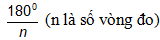
9. Measurement sighting must be objective, meticulous, and accurate, carried out strictly according to the prescribed measurement operation procedures. Measurement results must be recorded clearly and neatly. Corrections to second readings are not allowed. Errors in degree and minute readings may be corrected (crossing out incorrect numbers, writing correct numbers above, without overwriting characters, and without continuous corrections). The format for recording traverse measurements is specified in Appendix 3 of this Circular.
10. It is permissible to use the automatic data recording function of the measuring device to directly record angle measurement data, edge measurement data, instrument height, mirror height, and point information in a data file. The data file can be printed on paper instead of the traverse measurement notebook.
11. After completing measurements at a station, preliminary calculations of angles and edges must be performed. Only if the measurement data meet the technical requirements can the station be moved. If the technical requirements are not met, remeasurement must be conducted.
12. Edges of the secondary control network must be converted to horizontal edges and adjusted for transverse cylindrical projection (UTM) and terrain elevation before error adjustment as follows:
a) Adjustment due to UTM projection at 3° zone:
b) Adjustment due to terrain elevation: Δs = -Sđo.h/R 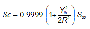
In the two formulas above:
- Sđo: is the horizontal length of the measured edge (m);
- h: is the average height of the edge (m);Technology and Environment on the establishment of the Journal of Standards- R: is the average ellipsoid radius, which can be applied as R=6378000m;
- Yđo: is the average Y coordinate value of the start and end points of the measured edge.
13. The secondary control network is adjusted separately on a plane, using a rigorous method. Software for adjusting traverse lines with calculation, adjustment, and evaluation of network element accuracy can be used:
a) Traverse closure error;tbb) Mean angle measurement error;
c) Relative mean edge error;
d) Mean position error of points. Final results for angles are rounded to seconds, coordinates and elevations are rounded to millimeters.
14. Submission results after measuring the secondary control network using the traverse method include:
a) Traverse measurement notebooks and measurement data files (if available);
b) Evaluation table of the network after adjustment;
c) Coordinates table after adjustment.
a) Traverse measurement book and measurement data file (if any);
b) Grid evaluation result table after adjustment;
c) Coordinate table after adjustment;
d) Diagram with location notes of points;
đ) Construction completion grid diagram.
Article 17. Level 2 Base Grid using Static GNSS Technology
1. The level 2 base grid may be measured using static GNSS technology, developed from high-grade control points of the level 1 base grid or higher.
2. The level 2 base grid measured using GNSS technology shall be designed as a triangular, quadrilateral, or chain of triangles covering the measurement area, connected to at least three high-grade control points of the level 1 base grid or higher. In cases where the number of new points ≤ 3, it is permissible to use two high-grade control points. Control points must be selected in controlling positions, evenly distributed, and as close to the grid as possible.
3. The position and coordinate points of the level 2 base grid measured using GNSS technology must comply with the provisions of Clause 4, Article 10 of this Circular and must be chosen to form horizontal direction pairs or horizontal direction pairs with one higher-level point to develop the control grid for mapping and detailed topographic surveying. Mark specifications comply with the provisions of Clause 2, Article 16 of this Circular.
4. The satellite signal receiver is a type of receiver capable of measuring Code and Phase values, single or multi-frequency, with a specified measurement edge error ≤ 10mm + 1mm.D (D is the length of the measured edge, in kilometers). The common satellite signal reception time of two receivers on one edge should not be less than 60 minutes for a single-frequency receiver and 45 minutes for a dual-frequency or higher receiver. When using a single-frequency satellite signal receiver, the length of the measured edge should not exceed 15km. For special measurements with edges significantly longer than the average edge length in the grid, the measurement duration must be increased by 10 minutes for every additional 5km beyond the average length.
5. The satellite signal receiver antenna must be fixed and securely placed on the point, accurately aimed at the mark center with an error ≤ 2mm; the antenna height must be measured with a steel tape, read twice to the millimeter. Station measurement parameters must be accurately collected and recorded in ink in the field measurement book including: date of measurement, time of measurement, machine number, point identifier, antenna type, antenna measurement method, obstacle diagram, weather conditions, measurer, and other special information if applicable. Field measurement book format complies with Appendix 3 of this Circular.
6. The name of the measurement data file (file) depends on the type of satellite signal receiver but must include basic information: point identifier, day of the year, session number within the day. Original measurement data must be organized and stored in a computer clearly, completely, and safely for convenient exploitation and verification at various levels.
7. Calculation and processing of measurement data are regulated as for the level 1 measurement grid under Clauses 1 and 2 of Article 12 of this Circular. After preliminary edge processing, a check of the closure error and geodetic height closure of the network must be conducted through the coordinate differences ΔX, ΔY, ΔZ and geodetic height difference ΔH of the processed edges as stipulated in Table 3 of this Circular.
8. The adjustment of the level 2 base grid measured using GNSS technology is carried out as prescribed for the level 1 base grid under Clauses 3 and 4 of Article 12 of this Circular.
9. To achieve technical tidal height accuracy, points within the level 2 base grid are connected to height control points, processed, and adjusted as prescribed for the level 1 base grid under Article 13 of this Circular.
10. Accuracy criteria for the level 2 base grid measured using static GNSS technology are defined as follows:
a) The mean error of the weakest point position does not exceed: ±0,02m;
b) Mean error of the weakest point height does not exceed: ±0.03m;
c) Relative mean error of the weakest edge does not exceed: 1:20,000;
d) Directional error does not exceed: ±10";
đ) Triangular closure error does not exceed ±0.05m.
11. The report on the adjustment results of the level 2 base grid measured using GNSS technology may use report templates of GNSS data processing software and be organized into groups of information:
a) Edge processing results;
b) Closure error;
c) Adjustment results of edge length, direction, and height difference;
d) Adjustment results of coordinates and height;
đ) Basic network parameters;
12. After completing the measurement, calculation, and adjustment of the level 2 base grid measured using GNSS technology, the following data must be submitted:
a) GNSS measurement data files for calculation and storage;
b) Field GNSS measurement books;
c) Measurement data summary tables compiled for each session in paper form and digital format (Microsoft Office Excel template);
d) On-site construction measurement diagrams of the coordinate grid printed on paper and in file format of graphic software: *.dgn, *.dxf, *.dwg;
đ) Report on the adjustment results of the grid.
Article 18. Technical Height Network
1. The technical height network is developed using geometric leveling methods, trigonometric height measurement methods, or static GNSS technology.
2. Depending on specific requirements, the technical height network may overlap some or all points of the Level 1 base network, the Level 2 base network, or establish separate markers to transmit heights to the control surveying network and for direct detailed topographic measurements. The technical height network is developed from national height grid points of Class IV or higher.
3. For areas requiring the transmission of Class IV heights to some or all points of coordinate grids, a Class IV height measurement network must be designed based on specific requirements. The provisions for constructing a Class IV height network comply with the National Technical Regulation on Building the National Height Network QCVN 11.2008/BTNMT.
Article 19. Technical Height Network Using Geometric Leveling Method
1. The technical height network is designed to transmit technical heights to some or all markers of the Level 1 base network, the Level 2 base network, depending on actual needs, and must be clearly stated in the technical design.
2. The technical height network using the geometric leveling method is designed as a single line or a line with one or more nodes, with the origin being national height points of Class IV or higher. In special difficult cases, hanging lines may be designed. The length of the hanging line does not exceed 4km and must be measured in both directions or in one direction with two different instrument heights of at least 10cm, taking the average of the two measurements.
3. The length of the single line depends on the basic uniform height difference to be surveyed and does not exceed the values shown in Table 8.
Table 8
|
Loperiodi height||| technicalt Torganize credit institutions, foreign bank branches are responsible for organizing the implementation of this Circular. |
Length ofpoliciestechnical height lineNo.according to each basic uniform height difference |
|||
|
0.25m |
0.5m |
1m |
2.5m and 5m |
|
|
Single Line (km) |
2 |
8 |
16 |
25 |
|
Between point gNo.c and node point (km) |
1,5 |
6 |
12 |
16 |
|
Between two node points (km) |
1 |
4 |
8 |
12 |
4. The measuring instrument is a geometric level with magnification of 20x or higher, the largest graduation value of the bubble tube is 45", corresponding to 2mm, using wooden staffs with one or two faces, the scale marking value is 1cm. If electronic levels with barcode staffs are used, machines and staffs with equivalent accuracy or higher must be used.
5. The technical height line is measured in one direction, the staff must be placed on a staff base or securely driven into the ground. Height differences are read to the millimeter midpoint of the telescope, distances are read as even numbers directly on the staff to meters. When using a double-faced staff:
- Read the black face, red face staff after;
- Read the black face, red face staff before; When using a single-faced staff:
- Read the staff after;
- Read the staff before;
- Change the instrument height by at least 10cm;
- Read the staff before;
- Read the staff after.
6. The distance from the instrument to the middle staff is 120m on average, with a maximum of 200m; the aiming height above the ground ≥ 0.2m; the difference in distance from the instrument to two staffs does not exceed 5m, the cumulative distance difference along the line does not exceed 5mm. The height difference on the station calculated from two staff faces or two instrument heights does not exceed 5mm. The total number of stations in the line must be an even number. Measurement results are recorded in the logbook according to the model in Appendix 3 of this Circular.
7. If an electronic level with barcode staff is used, the measurement procedure, distance, regulations, and technical specifications must comply with the machine's specifications.
8. The closure error of the technical height line does not exceed the value: Fh = ±50mm, where L is the length of the height line, in kilometers. If the number of stations exceeds 25 stations per kilometer, the closure error is calculated according to the formula: Fh = ±10mm, where n is the number of stations.
9. The height network must be rigorously adjusted according to the principle of least squares.
Article 20. Technical Elevation Grid Using Trigonometric Method
1. It is permitted to transmit technical elevation grades using the trigonometric height measurement method, utilizing electronic total stations to measure height differences. The measurement lines can be independent or coincide with the traverse grid, with the length of the line not exceeding the values listed in Table 8 of this Circular. Vertical angles may be measured independently or simultaneously during the traverse angle measurement process. Instruments used must have an angular measurement accuracy ≤10", with the number of vertical angle measurements equal to the number of horizontal angle measurements.
2. Height differences must be measured in both directions; the difference in vertical angle values between measurements ≤15". Parameters such as instrument height and reflector height must be accurately measured to within 1mm.
3. The height difference between two points is calculated based on the instrument height, reflector height, and the average vertical angle from the processed Measurement Origin (MO) errors. The average height difference is taken as the mean value of the two-way measurements.
4. The closure error for the height grid between elevation control points is Fh ≤ ±50mm, where L is the length of the line, measured in kilometers. The height grid must be rigorously adjusted according to the principle of least squares.
Article 21. Technical Elevation Grid Measured Using Static GNSS Technology
It is permitted to apply static GNSS technology to transmit technical elevation grades through a separate grid or concurrently during the measurement of first-order and second-order base network coordinates using static GNSS technology. In addition to the surveying requirements for first-order and second-order base networks, the technical elevation grid using static GNSS technology must also comply with the provisions regarding elevation control points, Geoid model, data processing, and adjustment calculations specified in Article 13 of this Circular.
Article 22. Control Survey Grid
1. The control survey grid is established to increase the density of control points for direct coordinate and elevation measurements of terrain and land features. The control survey grid combines the determination of coordinates and elevations within the same grid. The control survey grid is divided into two levels: Level 1 survey control grid and Level 2 survey control grid.
2. Depending on the conditions of the survey area, the coordinates of the control survey grid points can be determined using the traverse angle measurement method or GNSS technology. Elevations of the control survey grid points are determined using geometric leveling methods, trigonometric height measurement methods, or static and dynamic GNSS technologies while measuring coordinates.
3. The control survey grid must be designed on the largest scale map available in the survey area before construction begins.
4. Depending on specific requirements, the control survey grid points may be permanently or temporarily marked in the field. If permanent markers are installed, they must comply with the marker regulations in Appendix 1 of this Circular. If temporary markers are used, they must ensure the markers remain until the end of the survey and serve inspection and acceptance purposes.
Article 23. Level 1 Survey Grid Using Traverse Angle and Side Measurement Methods
1. The Level 1 survey grid is arranged in a single traverse line form or a grid with one or multiple nodes. The origin point for developing the Level 1 survey grid is a second-level or higher base network point. A traverse line must have enough origin points to create at least one initial direction, one initial coordinate point, and one point to close the coordinates. In difficult cases, it is permissible to apply a traverse connecting two non-aligned origin points but must be arranged to ensure a straight-line traverse form, with turning angles ≤8° or the ratio of the total traverse length to the distance between the initial and closing origin points [S]/L ≤1.3.
2. The lengths of the sides of the Level 1 survey grid should be nearly equal, with the difference in length between adjacent sides not exceeding twice, and each side not shorter than 20m; in particularly difficult areas, the shortest side may not be less than 10m, and grid sides must not intersect diagonally. If two Level 1 traverse survey grids intersect or the distance between the closest points of two grids ≤300m, a node connecting the two grids must be designed. The positional error of the weakest point and the closure error of the Level 1 survey grid are specified in Table 4 of this Circular.
3. The Level 1 survey grid must be measured twice using an electronic distance meter with an accuracy specification ≤10mm+1mm.D (D is the length of the side being measured, in kilometers).
4. Depending on the mapping scale, the accuracy of the measuring equipment used, and the average length of the traverse side, the number of sides of the Level 1 survey grid can be selected appropriately, as recorded in Table 9 as follows:
|
Percentage |
Mean Angle Measurement Error ±10" |
Mean Angle Measurement Error ±15” |
Mean Angle Measurement Error ±15" |
||||||||||||
|
100 |
200 |
300 |
400 |
500 |
100 |
200 |
300 |
400 |
500 |
100 |
200 |
300 |
400 |
500 |
|
|
1:500 |
9 |
9 |
7 |
6 |
6 |
8 |
6 |
5 |
4 |
3 |
7 |
5 |
4 |
3 |
2 |
|
1:1000 |
18 |
16 |
14 |
13 |
11 |
16 |
13 |
10 |
8 |
7 |
15 |
8 |
7 |
6 |
5 |
|
1:2000 |
34 |
32 |
29 |
25 |
23 |
31 |
25 |
20 |
16 |
14 |
28 |
20 |
15 |
12 |
9 |
|
1:5000 |
50 |
50 |
50 |
50 |
50 |
50 |
50 |
50 |
40 |
34 |
50 |
50 |
37 |
29 |
23 |
5. Angles within the traverse grid are measured using the full-circle method, with two station positions. Before measurement, the angle-measuring instrument must be checked and corrected for 2C and Measurement Origin (MO) errors. Depending on the accuracy specification of the angle-measuring instrument, the number of rounds required to achieve the corresponding mean square error of angle measurement in Table 9 is specified in Table 6 of this Circular.
6. The elevation of the Level 1 survey grid points can be measured using trigonometric height measurement methods, simultaneously measuring vertical angles with horizontal angles at two station positions in both directions, or applying geometric leveling methods. The closure error for the height grid is Fh ≤ ±75mm, where L is the length of the traverse, measured in kilometers.
7. In all cases, the measuring instruments, targets, and reflectors must be centered with an error ≤±5mm, and parameters such as instrument height and reflector height must be accurately measured to within millimeters.
8. The sighting must be objective, accurate, and carried out in accordance with the prescribed procedures for measurement operations. Measurement results must be recorded clearly and neatly. Corrections to second readings are not allowed. When there is confusion, readings of degrees and minutes can be corrected (crossing out incorrect numbers and writing correct numbers above them, without overwriting characters or making continuous corrections). The format of the measurement notebook is the same as that for the traverse grid notebook, as specified in Appendix 3 of this Circular.
9. It is permitted to use the automatic recording function of the measuring device to record angle measurement data, side measurement data, instrument height, reflector height, and point information in file format. Printed files of measurement data on paper can replace the field measurement data notebook.
10. The sides of the Level 1 survey grid must be converted to horizontal surfaces and corrected for UTM projection and topographic elevation before being adjusted according to Clause 12 of Article 16 of this Circular. The Level 1 survey grid for planimetry and elevation must be separately and rigorously adjusted according to the principle of least squares.
11. The results of the adjustment must include information about the grid:
a) Planimetric closure error, elevation traverse;
14. Submission results after measuring the secondary control network using the traverse method include:
a) Traverse measurement notebooks and measurement data files (if available);
d) Mean position error, point elevation.
Final angles should be rounded to seconds, coordinates and elevations to millimeters.
Article 24. Level 1 Survey Grid Using Static GNSS Technology
1. Static GNSS technology may be used to determine the coordinates and elevations of the level 1 survey grid simultaneously.
2. A level 1 survey grid constructed using static GNSS technology can be designed as a dense triangular network, chain of triangles, closed quadrilateral chain, connected to at least three level 2 or higher base points and two technical grade points. In small survey areas with up to three new points to be established, a triangular network connecting two base points and one elevation point is permitted. Base points and elevation points must be selected from control positions, evenly distributed, and as close to the grid as possible.
3. Points on the level 1 survey grid must ensure that the sky view angle is not less than 150°. In special cases, the sky view angle must not be less than 120° and only partial obstruction from one direction is allowed, facilitating the development of a level 2 survey grid using traverse methods and detailed measurements using total station methods. Only horizontal orientation points need to be chosen for each pair or horizontally oriented with one higher-grade point, without strict control over edge length and grid shape.
4. Equipment used must be satellite signal receivers capable of measuring Code and Phase values, single frequency or multi-frequency, with a specified measurement edge error ≤ 10mm+1mm.D (D is the measured edge length in kilometers).
5. Satellite signal reception time at each edge must be no less than 45 minutes for single-frequency receivers and 30 minutes for dual-frequency or higher receivers. If a measurement has an edge length significantly longer than the average, the measurement time for that edge must be extended by 10 minutes for every additional 5 km beyond the average edge length. Single-frequency receivers cannot measure edges longer than 15km.
6. The phase center of the GNSS receiver antenna must be centered with an error ≤ 5mm. Antenna height must be measured to the millimeter.
7. Processing procedures for measurement results, grid adjustment, calculation formats for grid adjustment results, and submission documents must comply with the provisions of Clauses 7, 8, 9, 11, and Clause 12 of Article 17 of this Circular.
8. Accuracy criteria for the level 1 survey grid measured using static GNSS technology are defined as follows:
a) The mean position error of the weakest point shall not exceed: ±0,03m;
b) The mean elevation error of the weakest point shall not exceed: ±0,04m;
c) The mean relative error of the weakest edge shall not exceed: 1:10,000;
d) The mean azimuth error shall not exceed: ±20";
đ) Triangular closure error does not exceed ±0.05m.
Article 25. Level 2 Survey Grid
1. The level 2 survey grid is the final control grid permitted to develop if the density of control points in the higher-level grid is insufficient to complete the survey area. Base coordinate and elevation points for developing level 2 survey grid points are level 1 or higher survey grid points. Position error of the weakest point and closure error of the level 2 survey grid coordinates are specified in Table 4 of this Circular.
2. Methods for developing the level 2 survey grid include angular distance traverse method, suspended traverse method, electronic total station intersection method, or static GNSS measurement technology, dynamic GNSS measurement technique.
3. A level 2 survey grid measured using the traverse method is arranged in a single traverse line or a grid with one or more nodes. A traverse line must have enough base points to create at least one initial azimuth, one initial coordinate point, and one closure point. It is permissible to apply a traverse with two non-aligned base points but must be arranged to ensure a straight traverse line, with the maximum turning angle ≤ 8° or the ratio between the total traverse length and the distance between the starting and closing base points [S]/L ≤ 1.3.
4. Edge lengths of the level 2 survey grid are measured twice using an electronic distance meter with a specified accuracy ≤ 10mm+1mm.D (D is the measured edge length in kilometers).
5. Depending on the scale of the survey, the accuracy of the measuring equipment used, and the average length of the traverse edges, the number of edges in the level 2 survey grid can be selected appropriately, recorded in Table 10 as follows:
|
Percentage |
Mean Angle Measurement Error ±10" |
Mean Angle Measurement Error ±15” |
Mean Angle Measurement Error ±15" |
||||||||||||
|
50 |
100 |
200 |
300 |
400 |
50 |
100 |
200 |
300 |
400 |
50 |
100 |
200 |
300 |
400 |
|
|
1:500 |
12 |
12 |
11 |
10 |
9 |
12 |
11 |
9 |
7 |
6 |
12 |
10 |
7 |
5 |
4 |
|
1:1000 |
25 |
24 |
22 |
20 |
18 |
24 |
23 |
18 |
14 |
11 |
23 |
20 |
14 |
10 |
8 |
|
1:2000 |
50 |
49 |
45 |
41 |
36 |
49 |
45 |
36 |
28 |
23 |
47 |
40 |
28 |
21 |
16 |
|
1:5000 |
55 |
55 |
55 |
55 |
55 |
55 |
55 |
55 |
55 |
55 |
55 |
55 |
55 |
52 |
40 |
6. The edge length of the level 2 survey grid must not be shorter than 20m. In difficult areas, the shortest edge length may be no less than 5m; the length difference between two consecutive traverse edges must not exceed 2.5 times. The positioning error of the instrument and the target must not exceed 5mm.
7. Traverse angles within the grid are measured using the full-circle method, with readings taken from two positions. The instrument must be checked and corrected for 2C and MO errors. Depending on the specified accuracy of the instrument for angle measurement, the number of rounds required to achieve the corresponding mean angle measurement error as specified in Table 10 is defined in Table 6 of this Circular.
8. The elevation difference between two points on the level 2 survey grid is determined using trigonometric leveling, with vertical angles measured simultaneously during the horizontal angle measurement process. Elevation differences are measured twice in both directions and the average value is taken. Instrument elevation, mirror elevation, and target elevation are measured to centimeters. Closure error of the elevation traverse Fh ≤ ±100mm, where L is the traverse length in kilometers. Coordinates and elevations of the level 2 survey grid must be adjusted separately and rigorously according to the principle of least squares.
9. The level 2 survey grid may be designed with suspended traverses, with the number of suspended edges specified as two, and in particularly difficult areas, no more than four suspended edges. All cases of suspended traverse development must be carried out first, separately from detailed measurements; edges, horizontal angles, and vertical angles must be measured in both directions; edge lengths and elevation differences must be taken as the average of the two-way measurements.
10. Coordinates and elevations of points on the level 2 survey grid using the suspended traverse method are directly calculated from the measured horizontal angles, vertical angles, average two-way measurements, and separate coordinates and elevations of the base points.
11. When applying the reverse angle intersection method using electronic total stations, at least three primary control points from the first-order survey network must be used. In difficult cases, two primary control points may be used, but the selection of the intersection result must be accurate to avoid confusion with symmetrical points.
12. If the reverse angle intersection method is used, at least three primary control points from the first-order survey network must be utilized, and the position of the reverse intersection must be far from the circle passing through the three used control points.
13. Technical requirements for electronic total stations, measurement procedures, angle measurement results, distance measurement results, and station parameters used in developing the second-order survey network shall be applied as for the first-order survey network.
Article 26. Second-order Survey Network Using Static GNSS Technology
1. The second-order survey network constructed using static GNSS technology shall be designed as a dense triangular grid, chain of triangles, closed polygonal chains, connected to at least three primary control points from the first-order survey network or higher, and two elevation control points from the first-order survey network or higher. For small survey areas with newly established points not exceeding three, it is permissible to connect to two coordinate control points and one elevation control point. Control points should be selected in positions that dominate, evenly distributed, and closest to the network. Measurement points must ensure observation angles unobstructed by less than 150°. In special cases, the observation angle must not be less than 120° and only obstructed from one side, facilitating detailed measurements using the total station method. Only horizontal alignment points need to be chosen between pairs or with one higher-level point, without restrictions on edge length differences and network shape.
2. Equipment used shall be GNSS receivers capable of measuring Code and Phase values, single-frequency or multi-frequency, with a specified distance measurement error ≤ 10mm + 1mm.D (D is the measured edge length in kilometers). The antenna phase center must have an error ≤ 5mm. Antenna height must be measured to millimeters.
3. The signal reception time at each edge shall not be less than 30 minutes for single-frequency receivers and 25 minutes for multi-frequency receivers. If a measurement session has edges longer than several times the average edge, the measurement time for that edge must be extended by 10 minutes for every additional 5 km beyond the average edge length. With single-frequency receivers, the measured edge length shall not exceed 15km. Surveying and computation accuracy standards for the second-order survey network apply as for the first-order survey network under Article 24 of this Circular.
4. Accuracy criteria for the second-order survey network measured using static GNSS technology are defined as follows:
a) The mean position error of the weakest point shall not exceed: ±0,03m;
b) The mean elevation error of the weakest point shall not exceed: ±0,04m;
c) Relative mean error of the weakest edge shall not exceed: 1:5000;
d) Mean position error shall not exceed: ±30";
đ) Triangular closure error does not exceed ±0.05m.
Article 27. Second-order Survey Network Applying Post-processing Kinematic GNSS Technique
1. The post-processing kinematic GNSS technique may be applied to measure the second-order survey network. Dedicated equipment manufactured by specialized manufacturers and tested in Vietnam must be used. The measurement equipment includes GNSS receivers capable of measuring Code and Phase values, single-frequency or multi-frequency, with a specified distance measurement error ≤ 10mm + 1mm.D (D is the measured edge length in kilometers) and control devices with post-processing kinematic GNSS measurement functions.
2. For each measurement station, two GNSS signal receivers must be used at two base stations (Base) to form closed triangles together with mobile stations (Rover) at new measurement points. Base stations must be coordinate and elevation points with accuracy from the first-order survey network or higher, with clear sky conditions ensuring the ability to receive signals from most satellites present during the measurement period in the area where the base station is located.
3. If there are insufficient well-conditioned base points, base stations can be set up at points without coordinates but with good satellite signal reception conditions, and must be measured coincidently with existing base points within the survey area to ensure that the measurement station has at least three base points from the first-order survey network or higher, evenly distributed across all control positions throughout the measurement station for network adjustment. Measurements at these points must be conducted under fixed measurement conditions (Fixed) with at least 20 measurements in control point mode. The antenna at the base station and the mobile station antenna must have an error ≤ 5mm, and the antenna height must be determined to millimeters.
4. New points of the second-order survey network must be designed and measured in pairs or with one higher-level point, following a unified naming rule, marked with wooden stakes, nails, and paint to ensure correct identification and precise positioning, with appropriate distances between two points to facilitate the most effective detailed measurements using the total station method.
5. The maximum distance from the base station to the second-order survey network points shall not exceed 5 km for mapping scales of 1:500 and 1:1000, and not more than 10 km for topographic mapping scales of 1:2000 and 1:5000. Measurement can only be conducted under fixed measurement conditions (Fixed) and in control point mode with at least 20 measurements.
6. After completing field measurements, the results of developing the second-order survey network shall be processed and computed for network adjustment with technical criteria as for the second-order survey network using static GNSS technology under Article 26 of this Circular.
7. The post-processing kinematic GNSS technique may be applied for detailed terrain and object measurements in areas not obstructed by the sky and always in fixed measurement conditions (Fixed). The distance from the base station to the measurement point shall not exceed 5 km for mapping scales of 1:500 and 1:1000, and not more than 10 km for topographic mapping scales of 1:2000 and 1:5000, and measurements shall only be conducted within the control zones of the base points.
Article 28. Real-time Kinematic GNSS Technology for Level 2 Survey Grids
1. Real-time Kinematic GNSS technology may be applied to measure level 2 survey grids. Equipment must be manufactured by specialized manufacturers and tested in Vietnam. The measurement equipment includes GNSS receivers capable of measuring both Code and Phase values, either single frequency or multi-frequency, with a specified edge measurement error ≤ 10mm+1mm.D (D is the length of the measured edge in kilometers), and devices with real-time kinematic GNSS measurement functions.
2. For each measurement station, one base station (Base) must be set up at a coordinate origin point with elevation from the level 1 survey grid or higher, with clear sky conditions allowing reception of signals from all satellites at any time during measurements at the base station and rover stations (Rover) approaching new points to be measured.
3. During measurements at each station, at least two coordinate origin points and elevations from the level 1 survey grid or higher must be measured, evenly distributed around the control area of the measurement station according to the control point measurement mode (Control point) with at least 20 fixed measurements (Fixed) to standardize the local coordinate system if there are no prior parameters for accurate transformation between the World Geodetic System 1984 (WGS84) and the local coordinate system.
4. If there are no origin points with good satellite signal reception conditions, the base station may be set up at a point without coordinates but with the best satellite signal reception conditions, and must conduct measurements into at least three coordinate origin points and elevations from the level 1 survey grid or higher located in the control area of the measurement station according to the control point measurement mode (Control point) with at least 20 fixed measurements (Fixed) to standardize the coordinate system. The antenna at the base station and the rover station antenna must be centered with an error ≤ 5mm, and the antenna height must be determined to the millimeter.
5. In both cases, the coordinate and elevation errors at the origin points after standardization shall not exceed the errors of the level 2 survey grid points corresponding to the map scale required for mapping as stipulated in Table 4 of this Circular.
6. Level 2 survey grid points must be designed and measured in pairs or in conjunction with higher-level points, following naming rules, and placed at appropriate distances to ensure detailed measurements using total stations effectively.
7. The distance from the base station to the measurement point shall not exceed 5 km when mapping at scales of 1:500 and 1:1000, and 10 km when mapping at scales of 1:2000 and 1:5000. Simultaneously, measurements must be within the control area of standardized points. Level 2 survey grid measurements can only be conducted under fixed conditions (Fixed) and in control point measurement mode (Control point) with at least 20 fixed measurements.
8. Level 2 survey grid points must be named according to unified rules, marked with wooden stakes, nails, or painted on hard surfaces to ensure accurate identification and centering when using electronic total stations for detailed measurements and for inspection and acceptance work.
9. After completing field measurements, the results of developing the level 2 survey grid are compiled into a report including a list of points, main parameters of the measurement stations: base station points, standardized points, errors at standardized points, serving the preparation of technical reports.
10. Real-time Kinematic GNSS technology may be applied to detailed terrain and object measurements, transferring design points to the field in areas with clear sky conditions and always in fixed measurement mode (Fixed). The distance from the base station to the measurement point shall not exceed 5 km for mapping at scales of 1:500 and 1:1000, and shall not exceed 10 km for topographic mapping at scales of 1:2000 and 1:5000, and must be within the control area of points used for parameter standardization.
Article 29. Establishing second-level survey networks using real-time GNSS technology with a multi-base station system (CORS network)
1. Permission to use real-time GNSS technology with a multi-base station system to establish a second-level survey network is granted if the accuracy published by the system has been confirmed by the national management agency for surveying and mapping to be consistent with the required accuracy for developing the second-level survey network grid points.
2. Permission is granted to apply multi-base station GNSS measurement techniques in second-level control survey grids and direct detailed terrain surveys at scales of 1:500, 1:1000, 1:2000, and 1:5000 if the published accuracy of the system meets the technical requirements for the accuracy of the detailed map points to be established.
Chapter IV
TOPOGRAPHIC SURVEYING
Article 30. Detailed Survey of Survey Areas
1. The determination of coordinates for detailed points shall be conducted using polar coordinate methods (horizontal angles, vertical angles, and distances) which may employ electronic total stations, optical theodolites combined with electronic distance meters, steel tapes, or bamboo poles. Horizontal and vertical angles are measured only at one position.
2. The content of detailed surveys depends on the scale of the map, purpose, requirements, and scope of the topographic survey tasks:
a) For large-scale topographic surveys or the establishment of geographic information databases, the content of detailed surveys depends on the requirements of the map scale or technical regulations regarding the structure and content of the geographic information database to be established by the competent authority and must be specified in the technical design. Typically, direct surveys serve the creation of topographic maps with the following basic themes:
- Mathematical basis: Projection grid, plane control points, elevations;
- Population, economic and social infrastructure, related geographic features;
- Transportation;
- Hydrography;
- Vegetation cover;
- Boundaries;
- Topography.
b) For specialized surveys, the content of the survey is detailed in the technical design.
3. Geographic objects and features that need to have their coordinates and elevations measured with sufficient detail to meet the accuracy and content requirements of the map scale or geographic information database to be established are as follows:
a) Measurement distances and point density for certain map scales are not to exceed the values listed in Table 11;
|
Survey Scale |
Uniform Height Interval |
Point Density (m) |
Measurement Distance |
|||
|
Theodolite, Bamboo Pole |
Electronic Total Station (Angle Measurement Error s ≤ 30”, Distance Measurement ErrorNo. Terrain (m) ≤ 0,1m) |
|||||
|
Feature Boundary (m) |
Feature Boundary |
Feature Boundary (m) |
d (m)councillORSa vt Tt (m) |
|||
|
1:500 |
0,5 |
15 |
70 |
50 |
500 |
500 |
|
1:1000 |
0,5 |
20 |
150 |
80 |
500 |
750 |
|
1:2000 |
0,5 |
40 |
200 |
100 |
500 |
1000 |
|
1:5000 |
0,5 |
60 |
250 |
150 |
500 |
1500 |
b) Features with the shortest dimension ≥ 0.5mm on the map must have their detailed points' coordinates and elevations measured at characteristic positions to represent shape and size according to actual measurements. Detailed points must depict arcs with relative distances between peak and chord ≥ 0.2mm on the map. Features smaller than 0.5mm on the map only determine the center position to represent them non-proportionally;
c) Linear features with width ≥ 0.5mm on the map must be depicted proportionally, showing true position, length, and width. In cases where this is not possible, they are represented half-proportionally along the feature's centerline to indicate position and length;
d) For thick features, generalization or selective omission of content may be necessary to ensure the tolerance level of the map being created;
đ) Geometric relationships between features, especially linear ones, must not contradict reality.
4. Detailed content of digital topographic maps follows the provisions for creating topographic maps of corresponding scales, where each type of object must be distinguished for editing and printing purposes, or for automation. Below are some common basic contents:
a) Urban and socio-economic objects such as town halls, schools, healthcare facilities, orientation markers... are represented by symbols and place names. Fence boundaries are shown when the length exceeds 1cm on the map. Place names follow the National Place Names Directory, supplemented by local legal documents at the time of field survey; residential points (villages, neighborhoods, urban areas...) are indicated by name, number of households, and graphic representation. Residential graphics are shown through house density, architectural structures, and plant boundaries, with buildings drawn to scale noting the number of floors if two or more;
b) Transportation objects are depicted proportionally, including road edges and information about width, surface material, and names marked every 15 to 20cm on the map. Rural roads, village lanes, and fields' borders are shown, as well as stable field borders and connecting routes to the main transportation network. Transportation reinforcement works are indicated by embankment talus slopes according to the terrain slope direction when the height reaches 0.3m or more. Talus slopes wider than 0.3mm on the map must also show the toe line. Ancillary transportation works like bridges, culverts, tunnels, overpasses, railway stations, airports... are shown in relation to the road and rail networks;
c) Typical water body features are boundary lines of water surfaces, distinguishing between shoreline (the highest limit of water containment) and water edge (determined at the time of field survey) when the distance between them is 0.3mm or more. Flow direction is indicated based on terrain and actual survey conditions according to map symbol standards. Ponds, channels, irrigation works like levees, dams, water regulation structures, pumping stations are surveyed according to the requirements of the topographic map being created;
d) Plant layers must be distinguished by boundaries between vegetation zones or between vegetation zones and other land use statuses, combined with symbols corresponding to the types of plants as measured.
d) Boundary elements are transferred from border and administrative boundary records published and verified by authorized agencies and adjusted on-site according to the current legal documents of the locality at the time of map surveying. For digital maps, boundary elements must perfectly align with linear objects. For paper maps compiled according to the prescribed map symbols;
e) In cases where there has been no change in topography, follow the natural laws, topographic point measurements for various scales must comply with density requirements as stipulated in Table 11 of this Circular. Detailed landforms are represented by contour lines. Contour lines are interpolated from detailed elevation points using manual or automatic methods through specialized software;
g) Additionally, it is necessary to measure and represent elevations at characteristic topographical locations such as mountain peaks, saddles, convex points, concave points, slope change points, watersheds, water accumulation points, road junctions, etc. The measurement density must ensure 25 points per 1 square meter for map scales. In cases of sudden topographical changes, measure and represent characteristic topographical lines such as base lines, shoulder lines of cliffs, raised terrain, and deep-cut terrain, which should be shown by symbols like steep slopes, talus slopes, and height differences;
5. Surveying regulations at survey stations
a) When conducting surveys to establish maps and build geographic database foundations, the height of the tip of the bamboo pole is calculated and displayed on the map to 0.01 meters for scale ratios of 1:500, 1:1000, and 1:2000, and to 0.1 meters for a scale ratio of 1:5000;
b) At each survey station, additional orientation to two clear points must be established, during the survey process, orientation must be frequently checked, with deviations not exceeding ±1'30", and at least two common measurement points must be measured with each adjacent station for verification;
c) Before mapping, copies must be made of surrounding areas (if applicable) and preliminary connections must be carried out;
d) Survey data, diagrams of annotated points, coordinate values... are recorded in the field survey book. The format of the survey book is specified in Appendix 3 of this Circular. If electronic devices are used that can automatically measure and record data, the results are recorded in numerical form with the format of specialized software accompanying the measuring device. Printed paper files of these measurement data are permitted to replace field books;
đ) Each survey station must draw a station diagram, on which orientation points, detailed points, characteristic topographical points, and other necessary annotations are depicted. The scale of the diagram is approximately equal to the scale of the surveyed map. In cases where electronic survey equipment is used, detailed points are measured and recorded automatically, point attributes are encoded, and data are processed automatically on specialized software, then a station diagram is not required;
Chapter V
ACCEPTANCE TESTING AND SUBMISSION OF PRODUCTS
Article 31. Acceptance Testing of Products
1. The work of acceptance testing of surveying outcomes and topographic maps must be conducted in accordance with current regulations regarding inspection, review, and acceptance of surveying products;
2. The basis for inspection, review, and acceptance is the technical design approved by the competent authority and technical requirements set forth in this Circular;
3. Submitted survey products for inspection, review, and acceptance must be complete and organized according to types as specified in the technical design;
4. After being inspected, reviewed, and accepted, new construction products may only be submitted to management agencies.
Article 32. Packaging and submission of documents
1. The packaged and submitted results must be the inspected and accepted results that have met quality standards, bearing the seal and signature of the construction unit.
2. Surveying and mapping products must be packaged and submitted according to the list specified in the technical design.
3. Packaging specifications must comply with current regulations on submitting surveying and mapping products. Each type of submitted document must clearly indicate the survey area, scale, type of result, quantity, name of the construction unit, and the survey date.
Chapter VI
INSPECTION AND TESTING OF SURVEYING EQUIPMENT
Article 33. Calibration of surveying equipment
1. Distance measuring equipment (electronic total stations, Invar tapes, steel tapes) must be certified for calibration validity by the state management agency for surveying and mapping at the calibration site.
2. GNSS equipment used in control network surveys must be certified for calibration validity by the state management agency for surveying and mapping at the calibration site.
Article 34. Testing of surveying equipment
1. Prior to and during the execution of the project, electronic total stations, angle measuring instruments, and level instruments used in the project must be tested and verified according to the instructions provided with the equipment.
2. Invar rods must be tested for their actual length on standard equipment before conducting project measurements.
3. Level rods must be tested for their actual length using standard tapes before measuring the project.
Chapter VII
IMPLEMENTING PROVISIONS
Article 35. Effective Date
This Circular takes effect from February 15, 2016.
Article 36. Implementation Organization
The Vietnam National Mapping Agency is responsible for inspecting the implementation of this Circular.
During the implementation process, if there are any difficulties, agencies, organizations, and individuals shall promptly report them to the Ministry of Natural Resources and Environment for consideration and decision./.
DEPUTY MINISTER
원본 문서(PDF)
관계도
문서를 클릭하면 열립니다. 빨간 테두리=효력을 변경하는 관계.
번역본
이 문서는 다음 언어로 제공됩니다: