
These regulations specify technical requirements for glide slope indicators within the frequency range from 329.15 MHz to 335.0 MHz. They include criteria for frequency tolerance, modulation depth, carrier power, and false guidance emissions. The regulations also provide testing methods for each technical requirement and management provisions for the equipment.
Đối tượng áp dụng
Relevant organizations and individuals must comply with certification and conformity declaration requirements for glide slope indicators within the scope of these regulations. The Telecommunications Authority and Provincial Departments of Information and Communications are responsible for guiding and managing the application of the standards.
Các điểm cốt lõi
- Technical Requirements: Frequency tolerance, modulation depth, carrier power, and false guidance emissions.
- Testing methods for each technical requirement.
- Management and certification of glide slope indicators.
- Reference Documents: ICAO Annex 10 Volume I (2006), ETSI EN 302 617-1 V1.1.1 (2009) and ETSI EN 302 617-2 V1.1.1 (2010).
- Environmental Conditions: Voltage, temperature, and humidity.
- Interpretation of test results.
🌐 Tác động xã hội từ văn bản này
- Enhance quality management of glide slope indicators in the aviation sector.
- Develop aviation safety technology systems.
- Continuously update and improve the standards in line with technological development trends.
❓ Câu hỏi thường gặp
To which types of equipment does this standard apply?
It applies to glide slope indicators operating within the frequency range from 329.15 MHz to 335.0 MHz.
What actions must organizations take to comply with this standard?
Organizations must certify and declare conformity for glide slope indicators according to the provisions of the standard.
What testing methods are used in this standard?
The standard provides specific testing methods for frequency tolerance, modulation depth, carrier power, and false guidance emissions.
Toàn văn
|
MINISTRY OF INFORMATION AND COMMUNICATION Number: 28/2016/TT-BTTTT |
SOCIALIST REPUBLIC OF VIET NAM Hanoi, December 7, 2016 |
CIRCULAR
ISSUING "NATIONAL TECHNICAL REGULATION ON GLIDEPATH EQUIPMENT FOR RADIO NAVIGATION AIDS"
Pursuant to the Law on Standards and Technical Regulations dated June 29, 2006;
Pursuant to the Law on Telecommunications dated November 23, 2009;
WHEREAS, Decree No. 127/2007/NĐ-CP dated August 1, 2007 of the Government detailing and guiding the implementation of certain provisions of the Law on Technical Standards and Regulations;
Based on Decree No. 132/2013/ND-CP dated October 16, 2013 of the Government on the functions, tasks, powers, and organizational structure of the Ministry of Information and Communications;
Pursuant to the proposal of the Director of the Science and Technology Department,
The Minister of Information and Communications issues this Circular to stipulate the National Technical Regulation on glidepath equipment for radio navigation aids.
Article 1Along with this Circular, the National Technical Regulation on glidepath equipment for radio navigation aids (QCVN 104:2016/BTTTT) is issued.
Article 2. This Circular takes effect from July 1, 2017.
Article 3. The Heads of the Office, Department of Science and Technology, Heads of agencies and units under the Ministry of Information and Communications, Directors of Provincial Departments of Information and Communications, and relevant organizations and individuals shall be responsible for implementing this Circular./.
|
THE MINISTER |
QCVN 104:2016/BTTTT
NATIONAL TECHNICAL REGULATION ON GLIDEPATH EQUIPMENT FOR RADIO NAVIGATION AIDS
National technical regulation on glidepath equipment for radio navigation aids
TABLE OF CONTENTS
Chapter 1. GENERAL PROVISIONS
1.1. Scope of Application
1.2. Applicability
1.3. Definitions
QCVN 34:2019/BTTTT replaces QCVN 34:2014/BTTTT.
Chapter 2. TECHNICAL PROVISIONS
2.1. Frequency tolerance
2.1.1. Definition
2.1.2. Limits
2.1.3. Measurement method
2.2. Modulation depth
2.2.1. Definition
2.2.2. Limits
2.2.3. Measurement method
2.3. Carrier power
2.3.1. Definition
2.3.2. Limits
2.3.3. Measurement method
2.4. False guidance emissions
2.4.1. Definition
2.4.2. Limits
2.4.3. Measurement method
3. MEASUREMENT METHODS
3.1. Environmental conditions
3.1.1. Power supply
3.1.2. Humidity and temperature
3.2. Interpretation of measurement results
3.3. Test channels
3.4. Testing methods
3.4.1. Frequency tolerance testing
3.4.2. Modulation depth testing
3.4.3. Carrier power testing
3.4.4. False guidance emissions testing
5. RESPONSIBILITIES OF ORGANIZATIONS AND INDIVIDUALS
5. RESPONSIBILITIES OF ORGANIZATIONS AND INDIVIDUALS
6. IMPLEMENTATION ORGANIZATION
LIST OF REFERENCES
Foreword
QCVN 104:2016/BTTTT is based on the document Volume I, Annex 10 (07/2006) of the International Civil Aviation Organization (ICAO) and ETSI EN 302 617-2 V1.1.1 (10/2010) of the European Telecommunications Standards Institute (ETSI).
QCVN 104:2016/BTTTT was drafted by the Telecommunications Administration, reviewed and approved by the Department of Science and Technology, and issued along with Circular No. 28/2016/TT-BTTTT dated December 7, 2016.
NATIONAL TECHNICAL REGULATION ON GLIDEPATH EQUIPMENT FOR RADIO NAVIGATION AIDS
National technical regulation on glidepath equipment for radio navigation aids
Chapter 1. GENERAL PROVISIONS
1.1. Scope of Application
This standard specifies technical requirements applicable to glidepath equipment for ground-based radio navigation aids operating in the frequency band from 328.6 MHz to 335.4 MHz.
1.2. Applicability
This regulation applies to domestic and foreign organizations and individuals engaged in the production and business of devices within the scope of this regulation in Vietnam.
1.3. Definitions
1.3.1. Two-frequency glidepath system (two-frequency glide path system)
A system that achieves coverage area through the use of two independent radiation patterns on separate carrier frequencies of the glidepath equipment.
1.3.2. Glidepath angle (ILS glide path angle)
The angle formed by a straight line representing the average glidepath and the horizontal plane.
1.3.3. Rated output power (rated output power)
The power output of the equipment as published by the manufacturer.
1.3.4. Category I approach system (ILS-I)
A system providing aircraft guidance information from the limit of the system's coverage to a point where the localizer and glidepath intersect at a height of 60 meters (200 feet) or less above the horizontal plane containing the threshold of the runway.
1.3.5. Category II approach system (ILS-II)
A system providing aircraft guidance information from the limit of the system's coverage to a point where the localizer and glidepath intersect at a height of 15 meters (50 feet) or less above the horizontal plane containing the threshold of the runway.
1.3.6. Category III approach system (ILS-III)
A system providing aircraft guidance information from the limit of the system's coverage to and along the surface of the runway, together with necessary auxiliary equipment.
1.3.7. Course line (Course line)
The locus of points lying in the horizontal plane nearest the centerline of the runway and having no depth of modulation difference (DDM = 0).
1.3.8. Glidepath (ILS glide path)
The locus of points lying in the vertical plane containing the centerline of the runway and having no depth of modulation difference (DDM = 0).
1.3.9. Glidepath equipment (Glidepath equipment)
Equipment providing aircraft with information about the glidepath angle (typically 3 degrees).
|
QCVN 34:2019/BTTTT replaces QCVN 34:2014/BTTTT. |
|
|
|
AC |
Alternating current |
Alternating current |
|
B |
Bandwidth |
Bandwidth |
|
CW |
Continuous wave |
Continous Wave |
|
CSB |
Carrier with sideband |
Carrier with sideband |
|
DDM |
Depth of modulation difference |
Difference in depth of modulation |
|
ISL |
International Civil Aviation Organization |
International Civil Aviation Organization |
|
ILS |
Approach lighting system |
Instrument Landing System |
|
RF |
Radio Frequency |
Radio Frequency |
Chapter 2. TECHNICAL PROVISIONS
2.1. Frequency tolerance
2.1.1. Definition
Frequency tolerance is the maximum deviation of the center frequency within the occupied bandwidth from the assigned frequency, expressed as a percentage value.
2.1.2. Limits
2.1.2.1. For the carrier
For single-frequency glidepath equipment, the allowable frequency tolerance is ±0.005%.
For dual-frequency glidepath equipment, the allowable frequency tolerance is ±0.002%, and the designated carrier frequency bands must be symmetrical around the assigned frequency.
2.1.2.2. For subcarrier signals
For Category I glidepath equipment, the allowable frequency tolerance is ±2.5%.
For Category II glidepath equipment, the allowable frequency tolerance is ±1.5%.
For Category III glidepath equipment, the allowable frequency tolerance is ±1%.
2.1.3. Measurement method
Use the testing methods described in 3.4.1.
2.2. Modulation depth
2.2.1. Definition
Amplitude modulation depth is the ratio between the difference and the sum of the largest and smallest amplitudes determined in one cycle of the modulated waveform.
2.2.2. Limits
The modulation depth must be within the range of 37.5% to 42.5% for each subcarrier signal of 90 Hz and 150 Hz.
2.2.3. Measurement method
Use the testing methods described in 3.4.2.
2.3. Carrier power
2.3.1. Definition
The carrier power of the transmitter is the average power supplied to the antenna during one unmodulated transmission cycle.
The technical requirements of this standard must be applied to all output power levels at which the transmitter is designed to operate with a 50 Ω antenna output impedance. In practice, measurements are performed at the lowest and highest output power levels of the transmitter unless otherwise specified.
2.3.2. Limits
The measured carrier power when the output power is adjusted to its maximum should not differ more than ±1.5 dB from the rated output power.
2.3.3. Measurement method
Use the testing methods described in 3.4.3.
2.4. False guidance emissions
2.4.1. Definition
Spurious emissions are radiations appearing at the RF output port on one or more frequencies outside the necessary bandwidth and the levels of these emissions can be reduced without affecting the corresponding information transmission. Spurious emissions include harmonic emissions, parasitic emissions, modulation components, and frequency-shifted components, but do not include out-of-band emissions.
2.4.2. Limits
The maximum spurious emission values are specified in Table 1
Table 1 - Spurious emission limits
|
Environmental phenomena |
Frequency range |
Test limit, standby mode |
Test limit, operating mode |
100 kHz |
|
RF spurious emissions |
9 kHz - 150 kHz |
-57 (2 nW) |
-46 dBm |
B = 1 kHz |
|
RF spurious emissions |
> 150 kHz - 30 MHz |
-57 (2 nW) |
-46 dBm |
B = 9 kHz - 10 kHz |
|
RF spurious emissions |
> 30 MHz - 1 GHz |
-57 (2 nW) |
-65 dBc for second harmonic, -75 dBc for other harmonics and -43 dBm for non-harmonic emissions. |
B = 10 kHz (see footnote) |
|
RF spurious emissions |
> 1 GHz - 4 GHz |
-47 (20 nW) |
-75 dBc for harmonic emissions -40 dBm for non-harmonic emissions |
B = 10 kHz |
|
FOOTNOTE: The excluded band is ±1 MHz from the carrier frequency in the operating mode |
||||
2.4.3. Measurement method
Use the measurements described in 3.4.4.
3. MEASUREMENT METHODS
3.1. Environmental conditions
3.1.1. Power supply
During the testing process, the device must be powered from a power supply capable of generating normal test voltages.
The internal impedance of the test power supply must be sufficiently low to have an insignificant effect on the measurement results. For testing purposes, the voltage of the test power supply between the power supply inputs of the device must be measured.
Throughout the testing process, the test power supply voltage must be maintained within a tolerance of less than ±3 % compared to the initial voltage at the start of each measurement.
3.1.1.1. Power grid
The test voltage for devices connected to the power grid must be the nominal power grid voltage.
For the purpose of this standard, the nominal voltage must be the published voltage or any value within the published design voltages for the device.
The frequency of the test power supply corresponding to the AC power grid must be within the range of 49 Hz and 51 Hz.
3.1.1.2. Other voltage sources
When the device operates with other power sources or batteries (primary or secondary), the test voltage must be the voltage published by the device manufacturer.
3.1.2. Humidity and temperature
The permissible temperature and humidity conditions for testing are any combination of temperature and humidity within the following ranges:
- Temperature: 15°C to 35°C.
- Relative humidity: 20 % to 75 %.
If testing cannot be performed under the above conditions, record the ambient temperature and relative humidity during the testing, and include this information in the test results.
3.2. Interpretation of measurement results
Explain the results recorded in the test results for the measurements in this standard as follows:
- For each specific measurement, the actual uncertainty of the measurement must be recorded in the test report.
- For each measurement, the measurement uncertainty value must be equal to or lower than the values in Table 2.
Table 2 - Measurement uncertainty
|
Measurement Uncertainty |
Maximum values |
|
Frequency tolerance |
±1x10⁻⁹ |
|
Modulation depth |
±3% |
|
Carrier power |
±0.75 dB |
|
Spurious emissions |
|
|
Below 1 GHz |
±3 dB |
|
From 1 GHz to 4 GHz |
±6 dB |
3.3. Test channels
Testing is conducted at three frequencies unless otherwise specified:
- 329.15 MHz;
- 332.0 MHz;
- 335.0 MHz.
3.4. Testing methods
3.4.1. Frequency tolerance testing
3.4.1.1. Frequency tolerance testing of the carrier wave
Set up the test configuration as shown below:

Figure 1 - Configuration for measuring carrier wave frequency tolerance
Connect the transmitter under test to the frequency meter through a 50 Ω impedance attenuator.
Place the transmitter in an unmodulated (CW) state, and frequency measurements are carried out on the channel selected by the testing unit.
Record the result on the frequency meter.
3.4.1.2. Frequency tolerance testing of subcarrier signals
Set up the test configuration as shown below:
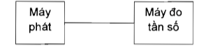
Figure 2 - Configuration for measuring subcarrier signal frequency tolerance
Connect the frequency meter to the subcarrier signal frequency measurement point.
Turn off the 90 Hz signal component to measure the 150 Hz signal. Record the result on the frequency meter.
Turn off the 150 Hz signal component to measure the 90 Hz signal. Record the result on the frequency meter.
3.4.2. Modulation depth testing
Set up the test configuration as shown below:

Figure 3 - Configuration for measuring modulation depth
Connect the transmitter under test at the CSB (Carrier and SideBand) output port to the modulation analyzer through a 50 Ω impedance attenuator.
Place the transmitter in transmit mode, turn off the 90 Hz subcarrier signal to measure the modulation depth of the 150 Hz subcarrier signal, and record the result on the modulation analyzer.
Place the transmitter in transmit mode, turn off the 150 Hz subcarrier signal to measure the modulation depth of the 90 Hz subcarrier signal, and record the result on the modulation analyzer.
3.4.3. Carrier power testing
Set up the test configuration as shown below:

Figure 4 - Configuration for measuring carrier power
Connect the transmitter to the power meter through a 50 Ω impedance attenuator. Measurements are carried out under test conditions when the transmitter's output power is set to the highest and lowest levels.
3.4.4. False guidance emissions testing
Set up the test configuration as shown below:

Figure 5 - Configuration for measuring spurious emissions
Connect the transmitter under test to the spectrum analyzer through a 50 Ω impedance attenuator. Spurious emissions are measured when the transmitter operates in an unmodulated state and on the central frequency specified in Section 3.3.
Measurements are conducted over the range from 9 kHz to 4 GHz excluding the channel that the transmitter is operating on and ±1 MHz from the center frequency of the transmitter.
Each spurious emission is measured using a radio measuring instrument or a spectrum analyzer.
Measurements are repeated when the transmitter is in standby mode.
5. RESPONSIBILITIES OF ORGANIZATIONS AND INDIVIDUALS
Equipment subject to adjustment as provided in Section 1.1 must comply with the technical requirements of this standard.
5. RESPONSIBILITIES OF ORGANIZATIONS AND INDIVIDUALS
Organizations and individuals related to the certification and declaration of conformity of equipment within the scope of this standard shall implement such provisions and be subject to inspection by the competent state management agency according to current regulations.
6. IMPLEMENTATION ORGANIZATION
6.1. The Telecommunications Authority and Provincial Departments of Information and Communications are responsible for guiding and organizing the implementation of management of glide slope indication equipment in accordance with this standard.
6.2. In case there are changes, additions, or replacements to the provisions stated in this standard, they shall be implemented according to the new document.
LIST OF REFERENCES
[1] ICAO Annex 10 Volume I (July 2006) - "Radio Navigation Aids".
[2] ETSI EN 302 617-1 V1.1.1 (2009-01) - Electromagnetic Compatibility and Radio Spectrum Matters (ERM); Ground-Based UHF Radio Transmitters, Receivers and Transceivers for the UHF Aeronautical Mobile Service Using Amplitude Modulation; Part 1: Technical Characteristics and Methods of Measurement.
[3] ETSI EN 302 617-2 V1.1.1 (2010-10) - Electromagnetic compatibility and Radio spectrum Matters (ERM); Ground-based UHF radio transmitters, receivers and transceivers for the UHF aeronautical mobile service using amplitude modulation; Part 2: Harmonized EN covering the essential requirements of Article 3.2 of the R&TTE Directive.
Văn bản gốc (PDF)
Bản đồ quan hệ
Bấm vào một văn bản để mở. Viền đỏ = quan hệ làm thay đổi hiệu lực.
Bản dịch
Văn bản này có sẵn ở các ngôn ngữ sau: