
This Appendix is the Record of Technical Safety Inspection Results and Monitoring the Operational Status of Explosion-proof Circuit Breakers Used in Underground Mines. It includes sections such as location inspection, installation work, external condition of the casing, grounding, operational parameters, leakage protection relay, interlocking leakage switch, power supply diagram, safety regulations and equipment operation procedures, safety devices, interlocking mechanism, explosion-proof joints, cable terminals of the main circuit and control circuit, signal penetration elements, cleaning and label inspection of the circuit breaker. Each item is recorded with specific date.
Scope of application
Explosion-proof circuit breakers used in underground mines
Key points
- Location inspection
- Installation work
- External condition of the casing
- Grounding
- Operational parameters
- Leakage protection relay, interlocking leakage switch
- Power supply diagram, safety regulations and equipment operation procedures
- Safety devices
- Interlocking mechanism
- Explosion-proof joints
- Cable terminals of the main circuit and control circuit
- Signal penetration elements
- Cleaning and label inspection of the circuit breaker
🌐 Social impact of this document
- To ensure technical safety for the operation of explosion-proof circuit breakers in underground mines
- Monitor and record the operational status of the equipment to take timely corrective measures
❓ Frequently asked questions
How is this book used?
This book is used to record the results of technical safety inspections and monitor the operational status of explosion-proof circuit breakers in underground mines. Each inspection item will be recorded with a specific date.
Who is responsible for this book?
The person responsible for these books is a technical staff member specialized in mine electromechanics.
Full text
|
MINISTRY OF INDUSTRY AND TRADE ____________ Number: 15/2021/TT-BCT
|
SOCIALIST REPUBLIC OF VIETNAM _______________________ Hanoi, October 29, 2021 |
CIRCULAR
Issuing Technical Regulations chuẩn on national safety 3. NATIONAL UNIVERSITIES ARE SUBJECT TO STATE MANAGEMENT BY THE MINISTRY OF EDUCATION AND TRAINING, THE MINISTRY OF SCIENCE AND TECHNOLOGY, OTHER MINISTRIES AND SECTORS, AND PEOPLE'S COMMITTEES AT ALL LEVELS WHERE NATIONAL UNIVERSITIES ARE LOCATED, WITHIN THE SCOPE OF THEIR FUNCTIONS AS PROVIDED BY THE GOVERNMENT AND IN COMPLIANCE WITH LAWS. in the Field of Teachers and Educational Institution Managers
for explosion-proof circuit breakers used in underground mines
________________
THE MINISTER OF INDUSTRY AND TRADE
Pursuant to the Law on Construction number 50/2014/QH13 amended and supplemented by Law number 03/2016/QH14, Law number 35/2018/QH14, Law number 40/2019/QH14 and Law number 62/2020/QH14;
WHEREAS, Law on Product Quality and Commodities No. 05/2007/QH12 dated November 21, 2007;
Pursuant to Decree No. 127/2007/NĐ-CP dated August 1, 2007 of the Government detailing the implementation of certain provisions of the Law on Standards and Technical Regulations; Decree No. 78/2018/NĐ-CP dated May 16, 2018 of the Government amending and supplementing certain provisions of Decree No. 127/2007/NĐ-CP dated August 1, 2007 of the Government detailing the implementation of certain provisions of the Law on Standards and Technical Regulations;
Pursuant to Decree No. 132/2008/NĐ-CP dated December 31, 2008 of the Government detailing the implementation of certain provisions of the Law on Product Quality; Decree No. 74/2018/NĐ-CP dated May 15, 2018 of the Government amending and supplementing certain provisions of Decree No. 132/2008/NĐ-CP dated December 31, 2008 of the Government detailing the implementation of certain provisions of the Law on Product Quality;
Pursuant to Decree No. 98/2017/NĐ-CP dated August 18, 2017, of the Government stipulating the functions, tasks, powers, and organizational structure of the Ministry of Industry and Trade;
At the proposal of the Director of the Department of Safety Technology and Industrial Environment;
The Minister of Industry and Trade issues the National Technical Regulation on Safety for Explosion-Proof Circuit Breakers Used in Underground Mines.
Article 1. Attached herewith is the National Technical Regulation on Safety for Explosion-Proof Circuit Breakers Used in Underground Mines.
Code: QCVN 14:2021/BCT.
Article 2. Effectiveness
This Circular takes effect from July 1, 2022.
Article 3. Implementation
The Head of the Ministry's Office, the Director of the Department of Safety and Environmental Technology; Heads of relevant agencies, organizations, and individuals are responsible for implementing this Circular./.
|
DEPUTY MINISTER DEPUTY MINISTER (Signed) Nguyen Sinh Nhat Tan |
SOCIALIST REPUBLIC OF VIET NAM
QCVN 14:2021/BCT
AMENDMENT 1:2025 QCVN 07:2023/BXD
ON SAFETY FOR EXPLOSION-PROOF CIRCUIT BREAKERS
USED IN UNDERGROUND MINES
National technical regulation on safety
for explosion-proof circuit breaker used in underground mine
HANOI - 2021
Preamble
QCVN 14:2021/BCT was drafted by the Drafting Board of the National Technical Regulation on Safety for Explosion-Proof Circuit Breakers Used in Underground Mines, reviewed by the Department of Industrial Safety and Environmental Protection under the Ministry of Industry and Trade, examined by the Ministry of Science and Technology, and issued by the Minister of Industry and Trade pursuant to Circular No. 15/2021/TT-BCT dated October 29, 2021.
AMENDMENT 1:2025 QCVN 07:2023/BXD
ON SAFETY FOR EXPLOSION-PROOF CIRCUIT BREAKERS
USED IN UNDERGROUND MINES
National technical regulation on safety
for explosion-proof circuit breaker used in underground mine
This technical regulation sets out technical requirements, testing methods, sampling procedures; management requirements; responsibilities of organizations and individuals producing, trading, and importing cigarettes.
Thông tư này quy định chi tiết khoản 4 Điều 38 Luật Thủy sản số 18/2017/QH14 đã được sửa đổi, bổ sung tại điểm c khoản 21 Điều 14 Luật số 146/2025/QH15.
This technical regulation specifies technical safety requirements and management for explosion-proof circuit breakers used in three-phase isolated neutral AC power networks in underground mines with flammable gases and dust explosions, as defined in Appendix A of this technical regulation. (hereinafter referred to as explosion-proof circuit breakers used in underground mines).
Thông tư này áp dụng đối với tổ chức, cá nhân có liên quan đến hoạt động kinh doanh đối tượng thủy sản nuôi chủ lực trên lãnh thổ Việt Nam.
This technical regulation applies to organizations and individuals producing, importing, testing, inspecting, using, and other individuals related to explosion-proof circuit breakers in underground mines within the territory of Vietnam.
In this technical regulation, the following terms are understood as follows:
3.1. Flammable atmosphere is a mixture of flammable substances in gaseous, vapor, dust, fiber, or floating form with air, in which, after ignition, flame can spread continuously.
3.2. Circuit breaker is a mechanical switching device capable of closing and opening circuits under normal conditions, as well as automatically opening circuits under abnormal conditions.
3.3. Main circuit of the circuit breaker is the entire electrically conductive part of the circuit used to transmit electrical energy to the load.
3.4. Auxiliary circuit of the circuit breaker is the entire electrically conductive part contained in control, measurement, and signal circuits. control circuit, measurement, signal.
3.5. Explosion-proof circuit breaker is a circuit breaker designed for use in environments containing flammable gases and dust explosions.
3.6. Isolator switch is a mechanical structure capable of closing or opening the circuit under no-load or negligible current conditions.
3.7. Cable entry and exit is a component used to receive and protect cable ends, seal the conductors and insulating materials of the cable with a filling compound or sealing ring attached to the equipment housing by threads or bolts.
3.8. Non-explosion-proof enclosure type "d" is a structure that contains parts that may ignite the explosive gas mixture and can withstand the pressure generated by the internal explosion of the explosive gas mixture and prevent the spread of the explosion to the surrounding flammable atmosphere. 3.9. Intrinsic safety protection type "i"
is a type of protection where the electrical energy of the equipment and its connected components when placed in a flammable atmosphere is limited below the level that could ignite the explosive mixture by spark or thermal effects. II. TECHNICAL SAFETY REQUIREMENTS
4.1. QCVN QTĐ-5:2009/BCT National Technical Regulation on Electrical Engineering - Volume 5 Inspection of Electrical Equipment Systems.
4. Referenced Documents
4.2. QCVN 01:2011/BCT National Technical Regulation on Safety in Underground Coal Mining.
4.3. QCVN 04:2017/BCT National Technical Regulation on Safety in Underground Metal and Non-Metal Mining.
4.4. TCVN 4255:2008 (IEC 60529:2001) Enclosure protection (IP code).
4.5. TCVN 6592-1:2009 (IEC 60947-1:2007) Low-voltage switchgear and controlgear - Part 1: General rules.
4.6. TCVN 6592-2:2009 (IEC 60947-2:2007) Low-voltage switchgear and controlgear - Part 2: Circuit-breakers.
4.7. TCVN 6627-1:2014 (IEC 60034-1:2010) Rotating electrical machines - Part 1: Characteristics and performance.
4.8. TCVN 7699-1:2007 (IEC 60068-1:1988) Environmental tests - Part 1: General and guidance.
4.9. TCVN 10888-0:2015 (IEC 60079-0:2011) Explosive atmospheres - Part 0: Equipment - General requirements.
4.10. TCVN 10888-1:2015 (IEC 60079-1:2014) Explosive atmospheres - Part 1: Equipment protection by non-explosion-proof enclosures "d".
4.11. TCVN 7079-7:2002 Equipment for underground mines - Part 7: Increased safety protection "e".
4.12. TCVN 7079-11:2002 Electrical equipment for underground mines - Part 11: Intrinsic safety protection "i".
4.13. TCVN 7079-17:2003 Electrical equipment for underground mines - Part 17: Testing and maintenance of equipment.
4.14. IEC 60079-7:2015 Explosive atmospheres - Part 7: Equipment protection by increased safety "e".
4.15. IEC 60079-11:2011 Explosive atmospheres - Part 11: Equipment protection by intrinsic safety "i".
4.16. IEC 60079-17:2013 Explosive atmospheres - Part 17: Electrical installation inspection and maintenance.
5. General Requirements
5.1. Explosion-proof circuit breakers used in underground mines must meet the technical safety requirements for general circuit breakers used in environments without flammable gases and dust explosions.
5.2. Basic technical parameter requirements
5.2.1. Rated alternating current voltage (U
) of the main circuit of the explosion-proof circuit breaker: 380 V, 660 V, 1 140 V.Average loan repayment period is 10 years;5.2.2. Rated working current (l
5.2.2. Rated working current (IAverage loan repayment period is 10 years;The rated current values for the explosion-proof circuit breaker: 100 A, 160 A, 200 A, 250 A, 400 A, 500 A, 630 A, 800 A, 1 000 A, 1 200 A.
5.2.3. Rated frequency of alternating current: 50 Hz.
5.2.4. Rated alternating current voltage of the auxiliary circuit (Uc): 18 V, 24 V, 36 V, 42 V.
5.2.5. Operating mode of the explosion-proof circuit breaker: Continuous.
5.3. Requirements for installation location of the explosion-proof circuit breaker
5.3.1. Tilt angle not exceeding ±15° from the horizontal position and at locations where safety structures are provided in tunnels, stations, and drifts. 5.3.2. Dry and adequately ventilated according to Article 42 of QCVN 01:2011/BCT for coal mines and Article 43 of QCVN 04:2017/BCT for ore mines.
5.4. Requirements for operating conditions
5.4.1. Ambient temperature from -20 °C to +40 °C; relative humidity value up to (98 ± 2) % at 35 °C;
5.4.2. Altitude not exceeding 1000 m above sea level and depth not exceeding 1500 m below sea level;
5.4.3. Voltage fluctuation range from 0.85 to 1.1 times the rated value;
5.4.4. In hazardous environments with flammable gases and explosive dust, dust concentration does not exceed 1200 mg/m
5.5. Requirements for grounding parts3.
5.5.1. Grounding requirements must comply with Clause 7.1.10 of TCVN 6592-1:2009 (IEC 60947-1:2007), Clause 20 of Article 102 of QCVN 01:2011/BCT, and Article 15 of TCVN 10888-0:2015 (IEC 60079-0:2011).
5.5.2. In cable compartments, there must be mechanisms to securely fasten grounding wires and weld them to the casing; cable glands must have mechanisms to securely fasten grounding wires.
5.6. Explosion-proof circuit breakers used in underground mines must have mounting brackets under the casing and hooks on top for ease of installation, movement, and operation.
5.7. The quick-opening cover of the explosion-proof circuit breaker must be mechanically interlocked to ensure: in 5.7.1. It can only be opened when the mechanisms: Handle-on-off; control power switch; isolation switch are in the off position.
5.7.2. The mechanisms mentioned in Point 5.7.1 cannot be closed when the quick-opening cover is open.
5.8. For remotely controlled explosion-proof circuit breakers, the isolation switch must be electrically interlocked with the circuit breaker's on-off circuit.
5.9. The force required to close and open the explosion-proof circuit breaker and isolation switch shall not exceed 350 N.
5.10. Explosion-proof circuit breakers must be supplied with matching cable glands or explosion-proof plug connectors.
5.11. Push buttons and handle positions of the explosion-proof circuit breaker must have non-erasable operation markings.
5.12. Stop buttons and grounding wire connection points must be red.
6. Requirements for the structural components of explosion-proof circuit breakers
Explosion-proof circuit breakers used in underground mines with flammable gases and explosive dust must be designed, manufactured, and tested in accordance with standards TCVN 10888-0:2015 (IEC 60079-0:2011), TCVN 10888-1:2015 (IEC 60079-1:2014); standard TCVN 7079-7:2002, TCVN 7079-11:2002, and the provisions of this technical regulation.
6.1. Main components of non-penetrating explosion-proof housing type "d" include:
6.1.1. Cable junction box.
6.1.2. Input and output cable glands, cable funnels.
6.1.3. Insulators passing through the walls and partitions of the explosion-proof enclosure.
6.1.4. Light-transmitting elements.
6.1.5. Control push buttons, switch locks.
6.1.6. Mechanisms for transmitting rotary or linear motion.
6.1.7. Locks, related holes, and empty elements.
6.1.8. Special clamping mechanisms.
6.1.9. Interlocking mechanisms.
6.1.10. Quick-opening covers.
6.2. Requirements
for non-penetrating
explosion-proof housing type "d" 6.2.1. Types of explosion-proof joints Explosion-proof joints must comply with Articles 5, 6, 7, and 8 of TCVN 10888-1:2015 (IEC 60079-1:2014) and the provisions of this technical regulation.
6.2.1.1. Explosion-proof joint type cylindrical plug without bolt holes as shown in Figure 1.
Note:
c - Width of the explosion-proof joint surface, mm.
d - Width of the explosion-proof joint cylindrical part, mm.
f - Clearance of the chamfered edge, mm.
L - Minimum width of the explosion-proof joint, mm; L = c + d with the condition: c ≥ 3.0 mm, f ≤ 1.0 mm.
T - Inner side of the equipment casing. Figure 1. Explosion-proof joint type cylindrical plug without bolt holes
6.2.1.2. Explosion-proof joint type cylindrical plug with bolt holes as shown in Figure 2.
a - Width of the explosion-proof joint cylindrical part, mm.
b - Width of the explosion-proof joint flat part to the bolt hole, mm.
i - Clearance of the cylindrical part of the explosion-proof joint, mm.
d - Width of the explosion-proof joint cylindrical part, mm.
I - Minimum distance from inside the equipment to the bolt hole, mm; I = a + b if i ≤ 0.2 mm.
L - Minimum width of the explosion-proof joint, mm.
Figure 2. Explosion-proof joint type cylindrical plug with bolt holes
6.2.1.3. Explosion-proof joint type flat flange as shown in Figure 3.
I - Minimum distance from inside the equipment to the bolt hole, mm.
a - Width of the explosion-proof joint cylindrical part, mm.
Figure 3. Explosion-proof joint type flat flange
6.2.1.4. Minimum distance from inside the equipment to the bolt hole must comply with the provisions of Table
d - Width of the explosion-proof joint cylindrical part, mm.
Table 1. Minimum distance from inside the equipment to the bolt hole.
I - Minimum distance from inside the equipment to the bolt hole, mm.
a - Width of the explosion-proof joint cylindrical part, mm.
I (mm)
L (mm) 1.
12.5 ≤ L< 25
|
6.2.1.5. Explosion-proof joint type flange with gasket as shown in Figure 4. |
G - Gasket. |
|
6 |
< 12,5 |
|
8 |
Figure 4. Explosion-proof joint type flange with gasket |
|
9 |
≥25 |
6.2.1.6. Explosion-proof joint type rotating shaft as shown in Figure 5.
d - Width of the explosion-proof joint cylindrical part, mm.
When operations require passing through the wall of the non-penetrating explosion-proof housing, the width of the joint must comply with Article 7 of TCVN 10888-1:2015 (IEC 60079-1).
I - Minimum distance from inside the equipment to the bolt hole, mm.
a - Width of the explosion-proof joint cylindrical part, mm.
Figure 5. Explosion-proof joint type rotating shaft
6.2.1.7. Explosion-proof joint type rotating shaft with bushing as shown in Figure 6.
d - Width of the explosion-proof joint cylindrical part, mm.
I - Minimum distance from inside the equipment to the bolt hole, mm.
Figure 6. Explosion-proof joint type rotating shaft with bushing
6.2.1.8. Explosion-proof joint type screw thread must comply with Clause 5.2.8 and 5.3 of TCVN 10888-T2015 (IEC 60079-1), as shown in Figure 7.
T - Thread pitch.
d - Width of the explosion-proof joint cylindrical part, mm.
I - Minimum distance from inside the equipment to the bolt hole, mm.
Y - Thread engagement length, mm.
α - Thread apex angle, degrees.
d - Width of the explosion-proof joint cylindrical part, mm.
Figure 7. Explosion-proof joint type screw thread
6.2.2. Minimum width and clearance of explosion-proof joints:
6.2.2.1. For joints of types: Plug, cylindrical, flange, rotating shaft: As specified in Table 2.
Minimum width and clearance of explosion-proof joints
Type of joint
Minimum width of joint L (mm)
Table 2. Minimum clearance (mm)
|
(cm |
V≤ |
Volume (cm |
||||||||||||||
|
Volume ) 500< V3) IIA 100 |
IIB3) 100 < IIA 500 |
Volume ) 500< V3Plug,≤ 2000 |
Volume ) 500< V3) 2 000 < IIA 5 750 |
IIB3) V >5 750 |
||||||||||||
|
I |
cylindrical, |
flange, |
I |
cylindrical, |
flange, |
I |
cylindrical, |
flange, |
I |
cylindrical, |
flange, |
I |
cylindrical, |
flange, |
||
|
rotating shaft |
6 |
0,30 |
0,30 |
0,20 |
- |
- |
- |
- |
- |
- |
- |
- |
- |
- |
- |
- |
|
Notation: I refers to equipment groups for mines with methane gas; IIA and IIB refer to equipment groups for mines with non-methane flammable gases as defined in Article 4.2 of TCVN 10888-0:2015 (IEC 60079-0:2011). |
9.5 |
0,35 |
0,30 |
0,20 |
0,35 |
0,30 |
0,20 |
0,08 |
0,08 |
0,08 |
- |
0,08 |
0,08 |
- |
0,08 |
- |
|
6.2.2.2. For screw thread joints, the following requirements must be met: |
12.5 |
0,40 |
0,30 |
0,20 |
0,40 |
0,30 |
0,20 |
0,40 |
0,30 |
0,20 |
0,40 |
0,20 |
0,15 |
0,40 |
0,20 |
0,15 |
|
6.2.2.2.1. At least five threads must engage each other. |
25 |
0,50 |
0,40 |
0,20 |
0,50 |
0,40 |
0,20 |
0,50 |
0,40 |
0,20 |
0,50 |
0,40 |
0,20 |
0,50 |
0,40 |
0,20 |
|
d - Width of the explosion-proof joint cylindrical part, mm. 6.2.2.2.2. Thread pitch ≥ 0.7 mm. |
||||||||||||||||
6.2.2.2.3. Thread apex angle equal to 60° (± 5°).
6.2.2.2.1. At least five threads must mesh with each other.
6.2.2.2.2. Thread pitch ≥ 0.7 mm.
6.2.2.2.3. The apex angle of the thread is 60° (± 5°).
6.2.2.2.4. The length of the thread engagement shall be ≥ 5 mm with V ≤ 100 cm.3.
6.2.2.2.5. The length of the thread engagement shall be ≥ 8 mm with V > 100 cm.3.
6.2.3. Special clamping mechanism
The clamping mechanism must comply with Article 9 of TCVN 10888-0:2015 (IEC 60079-0:2011) and Article 11 of TCVN 10888-1:2015 (IEC 60079-1:2014). All explosion-proof joints using bolted clamping must have anti-loosening washers and can only be opened using tools.
6.2.4. The interlocking mechanism must comply with Article 10 of TCVN 10888-0:2015 (IEC 60079-0:2011) and ensure proper functioning.
6.2.5. The quick-opening cover must have an interlocking mechanism; it can only be opened after power has been cut off and the interlocking mechanism has been released.
6.2.6. Cable entry to the device
Cable entries leading to the cable junction box of the explosion-proof circuit breaker must comply with Article 16 and Appendix A of TCVN 10888-0:2015 (IEC 60079-0:2011), Article 13 of TCVN 10888-1:2015 (IEC 60079-1:2014), and the following requirements:
6.2.6.1. Must be securely fastened to the device housing and have all necessary components for sealing and securing cables, including types of cable glands as shown in Figure 11.
d - Width of the explosion-proof joint cylindrical part, mm.
1- Rubber seal for cable.
2- Rubber-insulated cable.
3- Cable clamp detail.
4- Detail for cable entry to compress rubber gasket.
5- Device housing.
d - Outer diameter of rubber-insulated cable, mm.
D1 - Inner diameter of cable gland, mm.
D2, D3 - Outer, inner diameters of rubber gasket, mm.
Figure 11. Cable gland when connected.
6.2.6.2. The distance between the cable gland, gasket, and rubber-insulated cable shall comply with Table 3.
Table 3. Distance between cable gland, gasket, and rubber-insulated cable.
|
D2 (mm) |
Distance from D1 - D2 (mm) |
Distance from D3 - d (mm) |
|
<20 |
≤1 |
≤2 |
|
20 -:- 60 |
≤2 |
|
|
>60 |
≤3 |
6.2.6.3. Cable gland details must be tightened to ensure sealing performance.
6.2.6.4. Rubber gaskets must not crack, maintain good elasticity, and the cable must not be stretched or bent during assembly and operation.
6.2.6.5. In high-voltage cable glands using insulating filler material, the solidified filler must not have cracks.
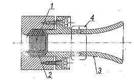
6.2.7. Unconnected cable glands must be sealed as shown in Figure 12 or other equivalent sealing methods.
1- Sealing plug.
2- Rubber seal.
3- Cable gland entry and exit detail for sealing.
4- Cable clamp detail.
Figure 12. Unconnected cable gland.
6.3. Light-transmitting elements
Light-transmitting elements must comply with Article 9 of TCVN 10888-1:2015 (IEC 60079-1:2014) and Article 26 of TCVN 10888-0:2015 (IEC 60079-0:2011).
6.4. Material for the housing
6.4.1. Non-metallic material
Non-metallic materials used to manufacture parts, components, and sections of the explosion-proof circuit breaker housing must comply with the provisions of Article 7 of TCVN 10888-0:2015 (IEC 60079-0:2011).
6.4.2. Metallic material
Metallic materials used to manufacture parts and sections of the explosion-proof circuit breaker housing must comply with the provisions of Article 8 of TCVN 10888-0:2015 (IEC 60079-0).
6.5. Insulation tubes (porcelain bushings), terminal blocks passing through walls and partitions of the housing must comply with the provisions of Article 11 of TCVN 10888-0:2015 (IEC 60079-0:2011) and ensure they are not damaged during wiring connections.
6.6. Connection means and cable junction boxes must comply with the provisions of Articles 14 and 15 of TCVN 10888-0:2015 (IEC 60079-0:2011).
6.7. The relative dielectric discharge index of insulating materials used in explosion-proof circuit breakers must comply with the provisions of Clause 4.4.1 of IEC 60079-7:2015, and the relative dielectric discharge index of solid insulating materials (CTI) as specified in Table 4.
Table 4. Relative dielectric discharge index of solid insulating materials.
|
Material group |
Relative dielectric discharge index (CTI) |
|
I |
600 ≤ CTI |
|
II |
400 ≤ CTI ≤ 600 |
|
Illa |
175 ≤ CTI ≤ 400 |
|
lllb |
100 ≤ CTI ≤ 175 |
Insulating materials used in circuits operating at voltages exceeding 250 V or carrying currents greater than 16 A must have a CTI value of no less than 400.
6.8. Requirements for clearance and creepage distances
Requirements for clearances between live parts and creepage distances on insulating surfaces must comply with the provisions of Clauses 4.3 and 4.4 of IEC 60079-7:2015 and as specified in Table 5.
Table 5. Clearance and Creepage Distances
|
Rated voltage UAverage loan repayment period is 10 years; (V) |
Minimum creepage distance (mm) |
Minimum clearance (mm) |
||
|
Material group |
||||
|
I |
II |
llla |
|
|
|
10 |
1,6 |
1,6 |
1,6 |
1,6 |
|
12,5 |
1,6 |
1,6 |
1,6 |
1,6 |
|
16 |
1,6 |
1,6 |
1,6 |
1,6 |
|
20 |
1,6 |
1,6 |
1,6 |
1,6 |
|
25 |
1,7 |
1,7 |
1,7 |
1,7 |
|
32 |
1,8 |
1,8 |
1,8 |
1,8 |
|
40 |
1,9 |
2,4 |
3,0 |
1,9 |
|
50 |
2,1 |
2,6 |
3,4 |
2,1 |
|
63 |
2,1 |
2,6 |
3,4 |
2,1 |
|
80 |
2,2 |
2,8 |
3,6 |
2,2 |
|
100 |
2,4 |
3,0 |
3,8 |
2,4 |
|
125 |
2,5 |
3,2 |
4 |
2,5 |
|
160 |
3,2 |
4 |
5 |
3,2 |
|
200 |
4,0 |
5,0 |
6,3 |
4,0 |
|
250 |
5,0 |
6,3 |
8 |
5 |
|
320 |
6,3 |
8,0 |
10,0 |
6,0 |
|
400 |
8 |
10 |
12,5 |
6 |
|
500 |
10,0 |
12,5 |
16,0 |
8,0 |
|
630 |
12,0 |
16,0 |
20,0 |
10 |
|
800 |
16,0 |
20,0 |
25,0 |
12 |
|
1 000 |
20 |
25 |
32 |
14 |
|
1 250 |
22 |
26 |
32 |
18 |
|
Note: - Operating voltage may exceed 10% of the voltage levels listed in the table above. - The values of creepage distance and clearance are based on the highest withstand voltage source within ±10% variation. |
||||
6.9. Requirements for parts of explosion-proof circuit breakers with "i" spark protection type must meet the following requirements:
6.9.1. The degree of protection of the outer enclosure of the explosion-proof circuit breaker (IP code) must be equal to or greater than IP54 as defined in TCVN 4255:2008 (IEC 60529:2001).
6.9.2. Components used in auxiliary circuits and other equipment must comply with the provisions of TCVN 7079-11:2002 or IEC 60079-11.2015.
6.9.3. Parameters R, L & C of the electrical circuit must ensure that when tested and evaluated according to the requirements of standard TCVN 7079-11:2002 or IEC 60079-11:2015, the test gas mixture is not ignited by sparks.
6.9.4. Any thermal effects generated in spark-safe circuits must ensure that the test gas mixture is not ignited due to surface heating.
6.9.5. Electrical circuits must be isolated from each other and from the equipment.
7. Technical requirements for explosion-proof circuit breakers used in underground mines
7.1. Type of switching, control: Explosion-proof circuit breakers used in underground mines with flammable gases and explosive dust must be one of the following types:
7.1.1. Direct manual switching;
7.1.2. Remote trip circuit; 7.1.3. Remote control;
7.1.4. Combination of the above types.
7.2. Requirements for electrical diagrams and construction
7.2.1. The electrical circuit of the explosion-proof circuit breaker must include:
7.2.1.1. Short-circuit protection;
7.2.1.2. Overload protection;
7.2.1.3. Protection of the control circuit against open circuit or short circuit of remote control wires;
7.2.1.4. Undervoltage release coil (Umin coil);
7.2.1.5. Overvoltage release coil (OK coil);
7.2.1.6. Preventing closing of the circuit breaker when:
7.2.1.6.1. The insulation resistance of the network to the load drops below the permissible value;
7.2.1.6.2. After the overcurrent protection has operated.
7.2.1.7. Signal about the closure of the circuit breaker; effect of short-circuit protection, overload protection, and interlocking earth leakage protection.
7.2.1.7. Signal indication for circuit breaker operation; effects of short-circuit protection, overload protection, and interlocking earth leakage protection.
7.2.1.8. Inspection regime for the operation of overcurrent protection devices and interlocked earth leakage protection devices.
7.2.2. Requirements for the structure of explosion-proof circuit breakers
7.2.2.1. Electrical circuit components must be placed in compartments with quick-opening covers that can be inspected and adjusted during operation.
7.2.2.2. Quick-opening covers must have interlocking mechanisms.
7.2.2.3. There must be schematic diagrams and wiring diagrams of the electrical circuits.
7.2.2.4. Compartments of explosion-proof circuit breakers:
7.2.2.4.1. Containing elements that frequently produce sparks during operation must be placed in non-sparking enclosures type "d" in accordance with TCVN 10888-1:2015 (IEC 60079-1:2011);
7.2.2.4.2. Not containing elements that frequently produce sparks must be protected against explosions with enhanced safety type "e" in accordance with TCVN 7079-7:2002 or IEC 60079-7:2015.
7.2.2.5. Remote control circuits and auxiliary circuits of explosion-proof circuit breakers must be intrinsically safe spark-proof type "i" with safety level ia or ib according to TCVN 7079-11:2002 or IEC 60079-11:2011.
7.2.2.6. Explosion-proof circuit breakers with remote control must have local control mode, ensuring closing from a control panel and tripping from all other control panels.
7.2.2.7. Control and protection units must have a mechanism to prevent incorrect installation.
7.2.2.8. The protection level of the outer casing of the block containing integrated control device elements, interlocking mechanisms, and protections must be manufactured with a minimum protection level of IP40 as specified in TCVN 4255:2008 (IEC 60529:2001).
7.3. Requirements for electrical parameters and characteristics
7.3.1. The limited breaking capacity of explosion-proof circuit breakers at rated voltage with power factor 0.30 ± 0.05 shall not be less than the values specified in Table 6.
Table 6. Limited Breaking Capacity Values of Circuit Breakers
|
Rated Current (A)Average loan repayment period is 10 years; (A) |
Rated Short-Circuit Breaking Capacity (kA) (kA) |
||
|
1,140 V |
660 V |
380 V |
|
|
63 < iAverage loan repayment period is 10 years; ≤ 125 |
3 |
4,5 |
7,5 |
|
125 < iAverage loan repayment period is 10 years; ≤200 |
4,5 |
7,5 |
9 |
|
200 < iAverage loan repayment period is 10 years; ≤ 400 |
7,5 |
9 |
12,5 |
|
400 < iAverage loan repayment period is 10 years; ≤ 500 |
9 |
12,5 |
15 |
|
500 < iAverage loan repayment period is 10 years; ≤ 630 |
12,5 |
15 |
20 |
|
630 < iAverage loan repayment period is 10 years; ≤ 1 000 |
15 |
20 |
30 |
|
1,000 < iAverage loan repayment period is 10 years; ≤ 1 600 |
20 |
30 |
40 |
7.3.2. The total number of cycles of closing and opening during operation, the number of cycles under load shall not be less than the values specified in Table 7.
Table 7. Total Number of Cycles of Closing and Opening
|
Rated Current (A) |
Operating Cycles Per Hour (Times) |
Total Operating Cycles (Times) |
||
|
Without Power |
With Power |
Total Cycles |
||
|
lAverage loan repayment period is 10 years; ≤ 100 |
120 |
8 500 |
1 500 |
10 000 |
|
100 < iAverage loan repayment period is 10 years; ≤315 |
120 |
7 000 |
1 000 |
8 000 |
|
315 < iAverage loan repayment period is 10 years; ≤630 |
60 |
4 000 |
1 000 |
5 000 |
|
630 < iAverage loan repayment period is 10 years; ≤ 2 500 |
20 |
2 500 |
500 |
3 000 |
|
2,500 < iAverage loan repayment period is 10 years; |
10 |
1 500 |
500 |
2 000 |
7.3.3. The mechanical endurance of the interlocked isolating switch must ensure operation for at least 2,500 cycles of closing and opening.
7.3.4. Explosion-proof circuit breakers must have overcurrent protection on at least two phases with adjustable settings.
7.3.4.1. The range of adjustment for overcurrent protection must be within the limit of 3 to 10 times the rated current of the release mechanism.
7.3.4.2. The operating error of the overcurrent protection at each setting in air:
7.3.4.2.1. Must be within ± 10% at temperature (25 ± 10) °C.
7.3.4.2.2. Additional ± 5% of the value specified in 7.3.4.2.1 at temperatures from -10 °C to +15 °C and from +35 °C to +60 °C.
7.3.4.3. The total tripping time of the explosion-proof circuit breaker shall not exceed 0.05 seconds when the short-circuit current is 1.5 times the set value of the overcurrent protection and also when the release mechanism acts independently.
7.3.5. Explosion-proof circuit breakers with overload protection for electric motors must comply with the provisions specified in Table 8.
Table 8. Overload Protection Time
|
Overload Current/Set Current Ratio |
Action Time |
State of Release Mechanism |
|
1,05 |
2 hours without tripping |
Cold state |
|
1,2 |
From 0.2 hours to 1.0 hour |
Heating state |
|
1,5 |
From 90 seconds to 180 seconds |
Heating state |
|
2,0 |
From 45 seconds to 90 seconds |
Heating state |
|
4,0 |
From 14 seconds to 45 seconds |
Heating state |
|
6,0 |
From 8 seconds to 14 seconds |
Cold state |
7.3.6. Low voltage protection must comply with the provisions of Clause 7.2.1.3 of TCVN 6592-1 (IEC 60974-1:2007) and the following requirements:
7.3.6.1. The circuit breaker must trip when the voltage drops below 70% of the rated voltage.
7.3.6.2. The circuit breaker must close reliably when the supply voltage is ≥ 85% of the rated voltage.
7.3.6.3. The delay time of the low voltage protection action shall not exceed 5 seconds.
7.3.7. Parallel release mechanisms must comply with the provisions of Clause 7.2.1.4 of TCVN 6592-1:2009 (IEC 60947-1:2007) and trip the circuit breaker reliably within the range of 70% to 110% of the rated voltage.
7.3.8. The permissible increase in temperature of contacts when working at rated current and voltage up to the permitted limit in ambient temperature of 35 °C shall not exceed the temperature specified in Table 9.
Table 9. Permissible Increase in Temperature of Contacts in Circuit Breakers
|
Part of the Circuit Breaker |
Permissible Temperature Rise (Long-Term Operation Mode) |
|
Main circuit contact points with silver-based ceramic-metal inserts |
According to the maximum temperature of adjacent parts |
|
Auxiliary circuit contact points with silver-based sintered inserts |
85 °C |
|
Contact points connecting the circuit breaker output to external cables |
75 °C |
7.3.9. The temperature rise of windings in circuit breakers as stipulated in Article 8 of TCVN 6627-1:2014 (IEC 60034-1:2010) and shall not exceed the limits specified in Table 10.
Table 10. Limits of Temperature Rise of Windings
|
Insulation Class |
Limit of Temperature Rise Measured by Resistance Method (K) |
|
120 (E) |
80 |
|
130 (B) |
90 |
|
155 (F) |
115 |
|
180 (H) |
140 |
|
Note: The temperature rise limits in the table are based on an ambient temperature of 40 °C. |
|
7.4. Insulation Requirements
7.4.1. Insulation resistance of the power circuit of explosion-proof circuit breakers:
7.4.1.1. When new and unused: not less than 10 MΩ.
7.4.1.2. When heated (corresponding to rated load); Comply with the provisions of Clause 16 of Article 106 QCVN 01:2011/BCT
7.4.1.3. Not less than 0.3 MΩ, after moisture resistance testing.
7.4.2. Insulation of explosion-proof circuit breakers and their components must withstand the test voltage of three-phase alternating current, frequency 50 Hz for 1 minute as specified in Table 11.
Table 11. Test Voltage for Insulation Strength of Explosion-Proof Circuit Breakers
|
Rated Voltage (V) |
Test Voltage (V) |
|
|
Before Moisture Resistance Testing |
After Moisture Resistance Testing |
|
|
The decision to switch the issuance of coats, overcoats, windbreakers, and down jackets to other uniforms for civil servants working at the National Market Management and Development Agency is decided by the Minister of Industry and Trade.Average loan repayment period is 10 years;≤24 |
500 |
250 |
|
24 < UAverage loan repayment period is 10 years; ≤ 60 |
1 000 |
500 |
|
60 < UAverage loan repayment period is 10 years; ≤ 250 |
2 000 |
1 000 |
|
250 < UAverage loan repayment period is 10 years; ≤ 660 |
2 500 |
1 300 |
|
660 < UAverage loan repayment period is 10 years; ≤ 1 000 |
3 500 |
2 000 |
|
The decision to switch the issuance of coats, overcoats, windbreakers, and down jackets to other uniforms for civil servants working at the National Market Management and Development Agency is decided by the Minister of Industry and Trade.Average loan repayment period is 10 years; >1 00 |
4 000 |
2 000 |
7.5. Requirements for Earth Leakage Protection Systems and Interlocked Pre-Closure Insulation before Energization.
Parameters of earth leakage protection of the operational power grid and interlocked pre-closure insulation preventing energization when there is earth leakage in explosion-proof circuit breakers as specified in Table 12.
Table 12. Parameters of Earth Leakage Protection of Earth Leakage Protection Devices and Interlocked Pre-Closure Insulation
|
Rated Voltage (V) |
Set Value of Single-Phase Earth Leakage Resistance (kΩ) |
Set value of the earth leakage lockout switch resistance (kΩ) |
Operating time with earth leakage resistance 1 (kΩ) (ms) |
|
380 |
3,5 |
7 |
≤200 |
|
660 |
11 |
22 |
|
|
1 140 |
20 |
40 |
|
|
Note: The earth leakage protection operating time is the circuit breaker's cut-off time from the moment of earth leakage; the error between the actual earth leakage resistance value and the value specified in Table 12 shall not exceed 20%. |
|||
7.6. The output of the explosion-proof circuit breaker must be protected against overvoltage during closing and opening by an RC protective device.
8. Requirements and testing methods
8.1. General requirements
Tests must be conducted under the following conditions:
8.1.1. Ambient temperature from -20 °C to +40 °C;
8.1.2. Relative humidity up to (98 ± 2) % at 35 °C;
8.1.3. Oxygen content is 21 % by volume;
8.1.4. No flammable gases, toxic gases, or corrosive vapors.
8.2. Testing of operating parameters.
8.2.1. The test content is carried out according to Appendix C of this Technical Standard, the test values are in accordance with TCVN 6592-1:2009 (IEC 60947-1:2007).
8.2.2. Operating parameters must be monitored in the operational position and when the circuit breakers are tilted 15 ° "forward" and "backward", "left" and "right"; at each position, the following must be performed:
8.2.2.1. Closing and opening at cold state at voltages of 0.85 and 1.1 times the rated voltage;
8.2.2.2. Checking the system operation during loss of voltage by removing the voltage.
8.2.2.3. Checking the signal when the circuit breaker is closed.
8.3. Mechanical interlock testing
8.3.1. Quick cover opening with mechanisms:
8.3.1.1. On-off handle;
8.3.1.2. Control switch;
8.3.2. Electrical interlocking between the handle and the circuit breaker closing circuit must be tested by pressing the "Stop" button and cutting off the handle.
8.3.3. Mechanisms meet the requirements if there are no cases of mechanical interlock mechanism damage during the tests.
8.3.4. The force required for on-off operation of the circuit breaker and the isolator switch must not exceed 350 N.
8.4. Insulation testing: The insulation of the explosion-proof circuit breaker is tested in accordance with Clause 7.4 of this Technical Standard.
8.5. Remote control circuit testing
When the remote control circuit is broken or short-circuited, the circuit breaker must:
8.5.1. Not be able to close in the open position;
8.5.2. Open when in the closed position.
8.6. Overcurrent protection testing
8.6.1. Testing the operation of the overcurrent protection must:
8.6.1.1. Use sinusoidal alternating current of 50 Hz frequency;
8.6.1.2. Set the test current higher than the set value by 10% to 15% of the rated current;
8.6.1.3. The overcurrent protection must operate and trip the circuit breaker, simultaneously lighting the indicator light.
8.6.2. Results of overcurrent protection testing
8.6.2.1. The average sum of three tests is the actual tripping current of the overcurrent protection.
8.6.2.2. The error of the overcurrent protection at each setting point must not exceed ± 10% at ambient temperature (25 ± 10) °C.
8.6.2.3. Additional error according to the requirement of 7.3.4.2.2 must not exceed ± 5%.
8.6.2.4. Testing is performed at three points within the range of settings: below, middle, and above.
8.6.3. Determining the short-circuit breaking time
8.6.3.1. Test with multiples of the test current and the set value equal to 1.5.
8.6.3.2. Conducted at three points on the protection scale: "bottom", "middle", and "top".
8.6.3.3. The operating time is the highest value of ten tests at the set point, which must not exceed 0.05 s.
8.7. Overload protection testing
8.7.1. Use sinusoidal alternating current of 50 Hz for testing.
8.7.2. Test results comply with the specifications in Table 8.
8.7.3. There must be a lit indicator light when the overload protection operates.
8.7.4. There must be a device to record the tripping time of the protection.
8.8. Low voltage protection testing
8.8.1. Use sinusoidal alternating voltage of 50 Hz;
8.8.2. Close the circuit breaker at the rated voltage;
8.8.3. Reduce the voltage to below 70% of the rated value, the circuit breaker must trip in both cases.
8.9. Parallel protection unit (OK coil) testing
8.9.1. Use sinusoidal alternating voltage of 50 Hz;
8.9.2. Close the circuit breaker at the rated voltage;
8.9.3. Supply the OK coil with voltage equal to 70% of the rated value, the circuit breaker must trip.
8.10. Earth leakage interlock testing
8.10.1. Test at the rated voltage;
8.10.2. Use adjustable resistors to connect between the phase wire and ground to determine the tripping resistance (three-phase and single-phase);
8.10.3. Test the operating time when there is a single-phase earth leakage with a resistance of 1 kΩ;
8.10.4. Test results must comply with the provisions in Table 12, Clause 7 of this Standard.
8.11. Explosion protection testing
The testing method is carried out in accordance with the provisions of TCVN 10888-0:2015 (IEC 60079-0:2011), TCVN 10888-1:2015 (IEC 60079-1:2014).
8.12. Spark safety testing
The testing method is carried out in accordance with the provisions of TCVN 7079-11:2002 (IEC 60079-11:2011).
9. Label regulations
9.1. Content on the label
The information on the label of the explosion-proof circuit breaker used in underground mines must include the minimum information as stipulated in Clause 1, Article 10 of Decree No. 43/2017/NĐ-CP dated April 14, 2017 of the Government regarding product labels and the circuit breaker parts must display the following contents:
9.1.1. Type, model;
9.1.2. Rated voltage, V;
9.1.3. Rated current, A;
9.1.4. Tripping current limit, KA;
9.1.5. Rated frequency, Hz;
9.1.6. Explosion protection type;
9.1.7. Protection level;
9.1.8. Explosion-proof certificate number;
9.1.9. Factory serial number;
9.1.10. Spark safety circuit parameters (if applicable);
9.1.11. Year of manufacture;
9.1.12. Weight, kg;
9.2. Material and location of the label
The label must be made of white steel or brass with a thickness of 1.5 mm, the information in the table must be engraved with a depth of no less than 0.5 mm, and must be arranged in a place that is easy to see and read, securely fastened to the housing by riveting or screwing.
9.3. Electrical schematic diagram plate
The electrical schematic diagram describing the operating principle and wiring method of the circuit breaker must amended and supplemented by Law No. 87/2025/QH15; be attached inside the housing wall.
8.2. Domestic-produced TNP1 explosive must declare compliance according to Circular No. 28/2012/TT-BKHCN dated December 12, 2012, issued by the Minister of Science and Technology regarding declaration of conformity to standards and technical regulations and methods of conformity assessment (hereinafter referred to as Circular No. 28/2012/TT-BKHCN) and Circular No. 02/2017/TT-BKHCN dated March 31, 2017, issued by the Minister of Science and Technology amending and supplementing certain provisions of Circular No. 28/2012/TT-BKHCN dated December 12, 2012, issued by the Minister of Science and Technology regarding declaration of conformity to standards and technical regulations and methods of conformity assessment (hereinafter referred to as Circular No. 02/2017/TT-BKHCN).
10. Conformity regulations
10.1. Explosion-proof circuit breakers within the scope of this Standard must declare conformity in accordance with the technical safety regulations in Part II of this Technical Standard, affix the conformity mark (CR mark) before entering the market; they must be inspected and tested during operation in accordance with Parts III and IV of this Technical Standard.
10.2. Domestic explosion-proof circuit breakers must comply with the conformity declaration requirements as stipulated in Circular No. 28/2012/TT-BKHCN dated December 12, 2012, issued by the Minister of Science and Technology on standard compliance declarations and technical regulation conformity declarations and methods for assessing conformity to standards and technical regulations, and Circular No. 02/2017/TT-BKHCN dated March 31, 2017, issued by the Minister of Science and Technology amending and supplementing certain provisions of Circular No. 28/2012/TT-BKHCN (hereinafter referred to as Circular No. 28/2012/TT-BKHCN and Circular No. 02/2017/TT-BKHCN).
10.3. Imported explosion-proof circuit breakers must comply with the national inspection registration requirements for imported goods as stipulated in Circular No. 36/2019/TT-BCT dated November 29, 2019, issued by the Minister of Industry and Trade on quality management of products and goods under the responsibility of the Ministry of Industry and Trade.
10.4. Conformity Declaration
10.4.1. The conformity declaration of explosion-proof circuit breakers must be based on the certification results from organizations that have registered their fields of operation according to the provisions of Decree No. 107/2016/NĐ-CP dated July 1, 2016, issued by the Government on business activities related to conformity assessment services (hereinafter referred to as Decree No. 107/2016/NĐ-CP); Decree No. 154/2018/NĐ-CP dated November 9, 2018, issued by the Government amending and supplementing certain provisions regarding investment and business conditions in the field of science and technology management by the Ministry of Science and Technology (hereinafter referred to as Decree No. 154/2018/NĐ-CP) and some provisions on specialized inspections or recognized according to the provisions of Circular No. 27/2007/TT-BKHCN dated October 31, 2007, issued by the Minister of Science and Technology guiding the signing and implementation of mutual recognition agreements and arrangements for conformity assessment results (hereinafter referred to as Circular No. 27/2007/TT-BKHCN).
10.4.2. Conformity Certification
10.4.2.1. For domestic production explosion-proof circuit breakers:
Conformity certification shall be conducted according to method 5 "Sampling test and production process evaluation; monitoring through sampling tests taken at the place of production or on the market combined with production process evaluation" at the explosion-proof circuit breaker manufacturing facility as stipulated in Clause 1, Article 5 of Circular No. 28/2012/TT-BKHCN.
10.4.2.2. For imported explosion-proof circuit breakers:
Conformity certification shall be conducted according to method 7 "Lot testing and evaluation" or method 5 "Typical sample testing and production process evaluation; monitoring through sampling tests taken at the place of production or on the market combined with production process evaluation" when requested by the foreign manufacturer according to the provisions of Clause 1, Article 5 of Circular No. 28/2012/TT-BKHCN.
10.4.3. Testing for certification purposes must be carried out by one of the following organizations:
10.4.3.1. Testing organizations as prescribed in Decree No. 107/2016/NĐ-CP, Decree No. 154/2018/NĐ-CP.
10.4.3.2. Testing organizations designated by the Ministry of Industry and Trade according to the provisions of Decree No. 74/2018/NĐ-CP, Decree No. 154/2018/NĐ-CP.
10.4.3.3. Organizations recognized according to the provisions of Circular No. 27/2007/TT-BKHCN.
10.4.4. The conformity mark must comply with the provisions of Clause 2, Article 4 of the regulations on standard compliance certification, technical regulation compliance certification, and standard compliance declaration, technical regulation compliance declaration issued together with Circular No. 28/2012/TT-BKHCN.
10.4.5. Procedures, formalities, and documentation for conformity declaration
Procedures, formalities, and documentation for conformity declaration for domestically produced and imported explosion-proof circuit breakers shall be implemented according to Circular No. 36/2019/TT-BCT dated November 29, 2019, issued by the Minister of Industry and Trade on quality management of products and goods under the responsibility of the Ministry of Industry and Trade.
11. Requirements for management file of explosion-proof circuit breakers used in underground mines
11.1. Must include all technical documents provided by the manufacturer, including: Transportation instructions, usage instructions, maintenance and storage instructions. In case of foreign language technical documents, they must be accompanied by a certified Vietnamese translation.
11.2. Organizations and individuals using explosion-proof circuit breakers must establish a management file from the time of initial use, including:
11.2.1. Approved design selection of explosion-proof circuit breakers.
11.2.2. Construction design and installation location of explosion-proof circuit breakers.
11.2.3. Post-installation acceptance report.
11.2.4. Installation completion report.
11.2.5. Inspection, testing, and calibration reports.
11.2.6. Operating procedures.
11.2.7. Technical safety inspection result logbook and operational status monitoring of explosion-proof circuit breakers used in underground mines.
11.2.8. Safety regulations, procedures for transportation, installation, inspection, operation, maintenance, repair, and storage of explosion-proof circuit breakers used in underground mines.
12. Requirements for inspection during operation
12.1. Technical feature inspection and evaluation shall be carried out according to QCVN QTĐ-5:2009/BCT, QCVN 01:2011/BCT, TCVN 4255:2008 (IEC 60529:2001), TCVN 6592-1:2009 (IEC 60947-1:2007), TCVN 6592-2:2009 (IEC 60947-2:2007), TCVN 10888-0:2015 (IEC 60079-0:2011), TCVN 10888-1:2015 (IEC 60079-1:2014), TCVN 7079-7:2002, TCVN 7079-11:2002, TCVN 7079-17:2003, IEC 60079-7:2015, IEC 60079-11:2011, IEC 60079-17:2013.
12.2. Inspection methods:
12.2.1. Visual inspection: Inspection without the need for equipment or tools.
12.2.2. Direct inspection: Inspection of external parts by visual means and determination of defects using tools and equipment. Direct inspection does not involve opening the casing or disconnecting power to the device.
12.2.3. Detailed inspection: Inspection which includes direct inspection contents and determination of defects using tools and equipment. Detailed inspection requires disconnection of power and opening of the device casing.
13. Inspection period and content
13.1. Responsibility and frequency of inspection:
13.1.1. Operators or on-duty electricians inspect every shift.
13.1.2. Deputy Workshop Mechanical and Electrical Director or authorized person inspects weekly.
13.1.3. Mechanical and Electrical Department Head or authorized person inspects quarterly.
13.1.4. Deputy Mine Mechanical and Electrical Director or designated persons inspect annually.
13.2. Inspection content shall be carried out according to the provisions of Appendix B of this Technical Regulation.
13.3. Inspection results must be:
13.3.1. Record in the inspection logbook in accordance with Appendix D of this Technical Regulation.
13.3.2. Conclude on the technical safety condition of the explosion-proof circuit breaker used in underground mines and only permit its use or continued operation when it meets the technical safety requirements.
13.4. When discovering equipment that does not meet safety requirements, the observer and operator must stop the operation and report to the responsible person for handling.
14. Requirements for testing and inspection
14.1. In accordance with the types of inspection, the tests and inspections must be carried out according to the technical guidelines, test methods, testing procedures, and testing equipment specified in the Technical Regulations and Standards QCVN QTĐ-5:2009/BCT, QCVN 01:2011/BCT, TCVN 4255:2008 (IEC 60529:2001), TCVN 6592-1:2009 (IEC 60947-1:2007), TCVN 6592-2:2009 (IEC 60947-2:2007), TCVN 10888-0:2015 (IEC 60079-0:2011), TCVN 10888-1:2015 (IEC 60079-1:2014), TCVN 7079-7:2002, TCVN 7079-11:2002, TCVN 7079-17:2003, IEC 60079-7:2015, (IEC 60079-11:2011, IEC 60079-17:2013.
14.1.1. The specific items and parameters of the tests and inspections shall be conducted in accordance with the technical standards applied and the manufacturer's guidance documents.
14.1.2. Measuring instruments (voltage, current, frequency, temperature, humidity meters; insulation resistance testers, gas concentration detectors, methane, hydrogen) used in the tests and inspections under this Technical Regulation must be calibrated and verified in accordance with the law on measurement.
14.2. Reporting and evaluating the results of testing and inspection
Reports and evaluations of the results of testing and inspection must clearly indicate whether the inspection and testing results meet the technical requirements set forth in the applicable standards and Technical Regulations.
14.2.1. Testing and inspection are considered satisfactory when they comply with the technical requirements of the standards and Technical Regulations listed in Table C of Appendix C of this Technical Regulation.
14.2.2. Testing and inspection are considered unsatisfactory when they fail to meet one of the technical requirements of the standards and Technical Regulations listed in Table C of Appendix C of this Technical Regulation.
IV. IMPLEMENTATION
15. Responsibilities of organizations and individuals
15.1. Organizations and individuals involved in the production, import, testing, inspection, and use of explosion-proof circuit breakers in underground mines must comply with the provisions of this Technical Regulation.
15.2. Organizations and individuals using explosion-proof circuit breakers in underground mines must:
15.2.1. Regularly inspect explosion-proof circuit breakers in accordance with regulations, promptly report to the competent authority when discovering incidents or signs of safety issues during operation.
15.2.2. Repair, maintain, test, and inspect explosion-proof circuit breakers in accordance with this Technical Regulation and other relevant legal documents.
15.2.3. Establish records for monitoring and safe use of explosion-proof circuit breakers in underground mines as stipulated in this Technical Regulation.
15.3. Testing and inspection organizations
Testing and inspection organizations must implement the contents prescribed in this Technical Regulation and bear responsibility for the results of testing and inspection in accordance with current regulations.
16. Implementation organization
16.1. The Department of Safety Technology and Industrial Environment, Ministry of Industry and Trade is responsible for:
16.1.1. Directing and organizing the implementation of the provisions of this Technical Regulation.
16.1.2. Inspecting and supervising the implementation of the contents prescribed in this Technical Regulation by organizations related to explosion-proof circuit breakers used in underground mines.
16.2. Provincial Departments of Industry and Trade shall organize inspections and supervision of the implementation of the contents prescribed in this Technical Regulation within their functions and powers.
17. Effective Date
17.1. This Technical Regulation takes effect from July 1, 2022.
17.2. In case the legal regulatory documents, technical regulations, and standards cited in this Technical Regulation are amended, supplemented, or replaced, the new provisions shall apply.
17.3. Organizations and individuals implementing this Technical Regulation, in case difficulties or obstacles arise during implementation, are advised to report to the Ministry of Industry and Trade for consideration and resolution./.
ANNEX A
HS CODE OF THE LIST OF PRODUCTS AND GOODS
WITHIN THE SCOPE OF REGULATION OF THIS TECHNICAL REGULATION
As stipulated in Circular No. 33/2017/TT-BCT dated December 28, 2017 of the Minister of Industry and Trade amending and supplementing the HS code in the List issued together with Circular No. 29/2016/TT-BCT dated December 13, 2016 of the Minister of Industry and Trade regulating the List of products and goods potentially causing safety hazards under the management responsibility of the Ministry of Industry and Trade.
|
Name of Product or Good |
HS Code |
|
Explosion-proof circuit breaker |
8535.21.10 |
|
8535.21.90 |
|
|
8535.29.00 |
Provisions on the HS Code of Terrestrial Mobile Radio Equipment and Terrestrial Radio Relay Equipment
CONTENTS OF INSPECTION
I. Shift Inspection:
The shift inspection contents are specified in Table B1.
Table B1. Provisions for shift inspection contents
|
Serial number |
Inspection Content |
Inspection method |
Inspection results allowing operation |
|
1 |
Circuit breaker position |
By direct visual inspection |
- Complying with Article 5.2 of this Technical Regulation. - No risk of rock falling and water dripping. |
|
2 |
Installation |
By direct visual inspection |
Firmly installed on a reliable foundation or bracket, wooden or concrete base, not displaced or vibrated during operation. Cable entry and exit correctly installed without being pulled tight or bent. |
|
3 |
External condition of the casing |
By direct visual inspection |
Intact without permanent damage or deformation. |
|
4 |
Grounding |
By direct visual inspection |
The grounding parts of the circuit breaker include: - Main grounding bar of the circuit breaker installation unit. - Grounding wires of the components, cable entries and exits. - Grounding wire of the earth leakage relay protection ≥ 5m from the main grounding bar. Must be complete and securely fastened. |
|
5 |
Check the operating parameters of the circuit breaker through the display panel or indicator meters. Noise of the circuit breaker |
By direct visual inspection |
Operating parameters include: voltage, current, earth leakage resistance of the network and other parameters before continuing operation. Review any fault notifications from the previous shift (if any). Normal noise without unusual sounds, vibrations, or impacts. |
|
6 |
Check the impact of the earth leakage relay protection, interlocking earth leakage switch |
By direct visual inspection |
- Test the impact of the earth leakage protection button. - Test the operation of the interlocking earth leakage switch. - Record the test results in the impact test result table. |
|
7 |
Check the electrical schematic diagram, safety rules, and operating procedures of the explosion-proof circuit breaker |
By direct visual inspection |
- Must have an accurate and clear main power supply schematic diagram that is updated to reflect the current status and is placed in an easily observable location, with circuit breaker protection parameters included in the power supply diagram. - Must have clear and easy-to-read operating procedures and regulations that are easily observable. |
|
8 |
Check safety equipment |
By direct visual inspection |
Must be fully ready for good working condition: fire extinguishing sand box, foam fire extinguishers, shovels, and other firefighting tools, safety isolation barriers. |
|
9 |
Check interlocking mechanisms |
By direct visual inspection |
The interlocking mechanisms for the quick-opening cover of the circuit breaker must remain intact without warping, damage that affects their interlocking function. |
|
10 |
Check explosion-proof joints |
By direct visual inspection |
- All explosion-proof joints (quick-opening covers, slow-opening covers, flanges, rotating shafts) must remain intact without deformation or permanent warping, and must have all correct type bolts with locking washers securely tightened. Incorrect type bolts shall not be used. - Operation of the circuit breaker is not allowed when any explosion-proof joint is missing bolts or is loose. |
|
11 |
Check cable connectors |
By direct visual inspection |
- Cable connectors must have all parts properly tightened, the type of cable used must be compatible with rubber cable glands and must be pressed tightly. - Grounding wires of cable connectors must be correctly installed. - Installed cables must not bear longitudinal force or bending force along the cable. |
|
12 |
Check light-transmitting elements for display or signal |
By direct visual inspection |
Light-transmitting elements for observing operational parameters or signaling must remain intact without cracks, breaks, permanent deformation, and must be securely fastened in position to ensure observation function. |
|
13 |
Clean and check transformer nameplates |
By direct visual inspection |
- Clean dust from the outer surface above the casing. - Nameplates must be complete, clean, legible, and free from damage, faded markings, and unclear visibility. |
II. Weekly inspection:
In addition to the daily inspection tasks, additional inspections according to the provisions in Table B2 must be conducted.
Table B2. Provisions for weekly inspection contents
|
Serial number |
Inspection Content |
Inspection method |
Inspection results allowing operation |
|
1 |
Explosion-proof joints of circuit breaker covers |
Directly |
- Inspect the clearance of explosion-proof joints around the circumference, ensuring technical requirements are met. - Tighten loose bolts. |
|
2 |
Explosion-proof joints of cable compartments of circuit breakers |
Directly |
- Inspect the clearance of explosion-proof joints around the circumference, ensuring technical requirements are met. - Tighten loose bolts. |
|
3 |
Cable connectors of power circuits and control circuits |
Directly |
Tighten all bolts of cable connectors and anti-loosening mechanisms. |
III. Quarterly inspection:
In addition to the weekly inspection tasks, additional inspections according to the provisions in Table B3 must be conducted.
Table B3. Provisions for quarterly inspection contents
|
Serial number |
Inspection Content |
Inspection method |
Inspection results allowing operation |
|
1 |
Explosion-proof joints of circuit breaker covers |
Directly |
Tighten all bolts or explosion-proof securing mechanisms, inspect the clearance of explosion-proof joints around the circumference, ensuring technical requirements are met. |
|
2 |
Explosion-proof joints of cable compartments of circuit breakers |
Directly |
|
|
3 |
Cable connectors of power circuits and control circuits |
Directly |
Tighten all bolts of cable connectors and anti-loosening mechanisms. |
|
4 |
Grounding system |
Directly |
- Inspect and reinforce the grounding system and measure ground resistance. - Ground resistance value must meet Rtđ ≤ 2 Ω, measured at any position. |
|
5 |
Protection system |
Directly |
Inspect the protective functions of the circuit breaker's protection systems. |
IV. Annual inspection:
In addition to the quarterly inspection tasks, additional inspections according to the provisions in Table B4 must be conducted.
Table B4. Provisions for annual inspection contents
|
Serial number |
Inspection Content |
Inspection method |
Inspection results allowing operation |
|
1 |
Rotating shaft-type joints (interlocking mechanisms, push buttons, handwheel shafts) |
Directly |
Tighten all bolts or explosion-proof securing mechanisms, inspect the clearance of explosion-proof joints around the circumference, ensuring technical requirements are met. |
|
2 |
Joints of light-transmitting elements, signals |
Directly |
Inspect the clearance of explosion-proof joints around the circumference, ensuring technical requirements are met. |
14.3. Inspection results must be recorded in the approved inspection logbook.
14.4. Inspection results must be processed and necessary decisions made to ensure safe operation of the equipment.
14.5. When an unsafe circuit breaker is detected, operations must be stopped and reported to responsible personnel for handling.
14.6. Inspection results
After inspection, conclusions about the technical safety condition of the explosion-proof circuit breaker used in underground mines must be drawn, and only those devices meeting technical safety standards may be put into use or continue operation.
Annex C
CONTENTS OF TESTING AND INSPECTION
I. Testing and inspection contents as prescribed in Table C
Table C. Provisions for testing and inspection contents
|
Serial number |
Testing and inspection contents |
Initial inspection |
Periodic inspection |
Abnormal inspection |
|
I |
Test explosion-proof performance of the circuit breaker for types "d" and "i" |
|
|
|
|
1 |
Inspect various explosion-proof joints: - Surface unevenness, leakage marks, scratches, grooves, etc. - Length of joints. - Clearance of joints. - Clearance from inside to bolt hole. - Threaded joints. - Light-transmitting element joints. - Environmental protection of joints. |
√ |
√ |
√ |
|
2 |
Inspect gaskets, sealing joints |
√ |
√ |
√ |
|
3 |
Materials for explosion-proof enclosure construction |
- |
- |
X |
|
4 |
Test thermal endurance of plastic materials used in enclosures |
- |
- |
X |
|
5 |
Test surface resistance of plastic materials |
- |
- |
X |
|
6 |
Test static charge accumulation of plastic materials |
- |
- |
X |
|
7 |
Inspect interlocking mechanisms |
√ |
√ |
√ |
|
8 |
Inspect integrity and proper installation of cable funnels, cable connectors of power and control circuits |
√ |
√ |
√ |
|
9 |
Inspect tightness and sealing of cable connectors, cable funnels of power and control circuits |
- |
- |
X |
|
10 |
Impact test for light-transmitting elements, plastic materials |
√ |
- |
X |
|
11 |
Thermal shock test for light-transmitting elements |
- |
- |
X |
|
12 |
Inspect integrity of grounding system components |
√ |
√ |
√ |
|
13 |
Inspect integrity of Ex filling elements |
√ |
√ |
x |
|
14 |
Test standard explosion pressure |
- |
- |
X |
|
15 |
Test over internal pressure (mechanical strength) of enclosure |
- |
- |
X |
|
16 |
Test non-propagation of explosion flame from inside to outside |
- |
- |
X |
|
17 |
Test torque for terminal posts and cable conduits |
√ |
- |
X |
|
18 |
Inspect clearance and creepage distance between live parts |
√ |
- |
X |
|
19 |
Test spark-proof control circuits |
- |
- |
X |
|
20 |
Inspect integrity of spark-proof control circuits |
√ |
√ |
X |
|
21 |
Inspect external condition of equipment enclosure |
√ |
√ |
√ |
|
II |
Test electrical technical features of circuit breakers |
|
|
|
|
1 |
Measure insulation resistance of circuit breaker components |
√ |
√ |
√ |
|
2 |
Test insulation endurance of circuit breaker components |
√ |
- |
√ |
|
3 |
Inspect reliable operation of mechanical and interlocking parts of circuit breakers |
√ |
√ |
√ |
|
4 |
Inspect operation of impact protection test system and signal system of circuit breakers |
√ |
√ |
√ |
|
5 |
Inspect contact resistance of power circuit contacts |
√ |
√ |
√ |
|
6 |
Inspect control and measurement transformers (Tu) |
√ |
√ |
√ |
|
7 |
Inspect control and measurement current transformers (Ti) |
√ |
√ |
√ |
|
8 |
Inspect and test the protective characteristics of the system (overload, short circuit, low voltage, phase loss) |
√ |
√ |
√ |
|
9 |
Inspect and test the operating characteristics of the earth leakage protection system and interlocking earth leakage protection system |
√ |
√ |
√ |
|
10 |
Inspect and test the tripping time of the circuit breaker's protection |
√ |
- |
√ |
|
11 |
Inspect the overvoltage switching protection device of the circuit breaker |
√ |
√ |
√ |
|
12 |
Inspect measuring devices |
√ |
√ |
√ |
|
d - Width of the explosion-proof joint cylindrical part, mm. - The symbol “√” indicates mandatory inspection and testing items. - The symbol “x” indicates inspection and testing items to be conducted when repair or major overhaul work involves changes to the structure and parameters of the electrical circuit that affect technical characteristics and explosion protection levels, or as required. - The symbol “-” indicates items that do not require inspection or testing. |
||||
Appendix D
BOOK OF INSPECTION RESULTS
SAFETY TECHNIQUE AND MONITORING OF OPERATING CONDITIONS
OF EXPLOSION-PROOF CIRCUIT BREAKERS USED IN UNDERGROUND MINES
Department, Construction Site, Workshop:…
Unit: ....
Start recording in this book from day … month … year ...
End recording on day … month … year ...
Part I
|
Serial number |
Inspection items |
Date, Month, Year |
|||
|
1 |
2 |
n |
31 |
||
|
1 |
Circuit breaker position |
|
|
|
|
|
2 |
Installation work inspection |
|
|
|
|
|
3 |
Inspection of the external condition of the housing |
|
|
|
|
|
4 |
Grounding inspection |
|
|
|
|
|
5 |
Inspection of the operational parameters of the circuit breaker through the display panel or meters and checking the noise of the circuit breaker |
|
|
|
|
|
6 |
Check the impact of the earth leakage relay protection, interlocking earth leakage switch |
|
|
|
|
|
7 |
Inspection of the power supply diagram, safety regulations, and equipment operation procedures |
|
|
|
|
|
8 |
Check safety equipment |
|
|
|
|
|
9 |
Check interlocking mechanisms |
|
|
|
|
|
10 |
Check explosion-proof joints |
|
|
|
|
|
11 |
Inspection of the power cable connections and control circuit connections |
|
|
|
|
|
12 |
Inspection of the joints of the light-transmitting elements and signal elements |
|
|
|
|
|
13 |
Cleaning and inspecting the labels of the circuit breaker |
|
|
|
|
|
14 |
Inspection of the explosion-proof joints of the circuit breaker cover plates |
|
|
|
|
|
15 |
Inspection of the explosion-proof joints of the cable connection compartments of the circuit breaker |
|
|
|
|
|
16 |
Protection system inspection |
|
|
|
|
|
17 |
Inspection of the shaft-type joint (interlocking mechanism, push button, shaft handle) |
|
|
|
|
|
18 |
Signature of the inspector |
|
|
|
|
|
19 |
Signature of the supervisor |
|
|
|
|
Part II
|
Date, month |
Record defects of mechanisms or equipment |
Repair methods for faulty parts and implementation time. Name of the person performing the repairs |
Evaluation of the repair completion. Signatures of the performer and the manager |
|
1 |
2 |
3 |
4 |
|
.... |
........................... |
................................... |
.................................. |
|
|
|
|
|
Instructions for recording
Part I: Record the status of the circuit breaker components, equipment, and mechanisms after inspection.
- Column 3 records in chronological order by date. In the column, record the symbols:
“T” - Indicates good condition of the component or assembly;
“H” - Indicates faulty component or assembly;
“CKT” - Indicates untested component or assembly.
- Remarks …(to be recorded by the assigned inspector).
Part II: Record defects (faulty components, extent of damage, and repair methods).
The assigned inspector records the nature and extent of damage of the components in Column 2 and marks “H” in Part I.
In Column 3, the manager records the repair plan for faulty components and the person responsible for implementing the repair plan.
Note:
a) The person responsible for these books is a technical staff member with expertise in mine electromechanical systems.
b) The book must be paginated and stamped with the mine's seal.
c) Quarterly and annual inspection results are not recorded in the book but are documented in minutes and include all technical safety inspection parameters. The deputy director in charge of electromechanical systems must review and sign the minutes./.
Original document (PDF)
Relations map
Click a document to open. A red border = a relation that changes validity.
Translations
This document is available in the following languages: