CIRCULAR
Issuing National Technical Regulations on safety for soft start explosion-proof equipment up to 6 kV used in underground mines
explosion-proof electromagnetic starters used in underground mines
__________
THE MINISTER OF INDUSTRY AND TRADE
WHEREAS, Law on Product Quality and Commodities No. 05/2007/QH12 dated November 21, 2007;
Pursuant to Decree No. 127/2007/NĐ-CP dated August 1, 2007 of the Government detailing implementation of certain provisions of the Law on Technical Regulations and Standards; Decree No. 78/2018/NĐ-CP dated May 16, 2018 of the Government amending and supplementing certain articles of Decree No. 127/2007/NĐ-CP dated August 1, 2007 detailing implementation of certain provisions of the Law on Technical Regulations and Standards;
Pursuant to Decree No. 132/2008/NĐ-CP dated December 31, 2008 of the Government detailing implementation of certain provisions of the Law on Product Quality; Decree No. 74/2018/NĐ-CP dated May 15, 2018 of the Government amending and supplementing certain articles of Decree No. 132/2008/NĐ-CP dated December 31, 2008 detailing implementation of certain provisions of the Law on Product Quality;
Pursuant to Decree No. 98/2017/ND-CP dated August 18, 2017 of the Government stipulating the functions, tasks, powers, and organizational structure of the Ministry of Industry and Trade;
At the proposal of the Director of the Department of Safety Technology and Industrial Environment;
The Minister of Industry and Trade promulgates the National Technical Regulation on Safety for Explosion-Proof Electromagnetic Starters Used in Underground Mines.
Article 1. This Circular promulgates the National Technical Regulation on Safety for Explosion-Proof Electromagnetic Starters Used in Underground Mines.
Code: QCVN 15:2021/BCT.
Article 2. Effective Date
This Circular takes effect from July 1, 2022.
Article 3. Implementation Organization
The Head of the Ministry's Office, the Director of the Department of Safety and Environmental Technology; Heads of relevant agencies, organizations, and individuals are responsible for implementing this Circular./.
QCVN 15:2021/BCT
NATIONAL TECHNICAL REGULATION ON SAFETY FOR EXPLOSION-PROOF ELECTROMAGNETIC STARTERS USED IN UNDERGROUND MINES
National technical regulation on safety for explosion-proof electromagnetic
SAYS
QCVN 15:2021/BCT was drafted by the Drafting Board of the National Technical Regulation on Safety for Explosion-Proof Electromagnetic Starters Used in Underground Mines, reviewed by the General Department of Safety Technology and Industrial Environment under the Ministry of Industry and Trade, examined by the Ministry of Science and Technology, and promulgated by the Minister of Industry and Trade pursuant to Circular No. 16/2021/TT-BCT dated October 29, 2021.
AMENDMENT 1:2025 QCVN 07:2023/BXD
ON SAFETY FOR EXPLOSION-PROOF ELECTROMAGNETIC
STARTERS USED IN UNDERGROUND MINES
National technical regulation on safety for explosion-proof electromagnetic
starter used in underground mine
This technical regulation sets out technical requirements, testing methods, sampling procedures; management requirements; responsibilities of organizations and individuals producing, trading, and importing cigarettes.
Thông tư này quy định chi tiết khoản 4 Điều 38 Luật Thủy sản số 18/2017/QH14 đã được sửa đổi, bổ sung tại điểm c khoản 21 Điều 14 Luật số 146/2025/QH15.
This technical regulation specifies technical safety requirements and management for explosion-proof electromagnetic starters in three-phase isolated neutral AC power networks used in underground mines with flammable gases and dust explosions, as specified in Appendix A of this technical regulation. (hereinafter referred to as explosion-proof electromagnetic starters used in underground mines).
Thông tư này áp dụng đối với tổ chức, cá nhân có liên quan đến hoạt động kinh doanh đối tượng thủy sản nuôi chủ lực trên lãnh thổ Việt Nam.
This technical regulation applies to organizations and individuals producing, importing, testing, inspecting, using, and other individuals related to explosion-proof electromagnetic starters in underground mines within the territory of Vietnam.
In this technical regulation, the following terms are understood as follows:
3.1. Flammable atmosphere is a mixture of flammable substances in gaseous, vapor, dust, or fiber form with air, in which conditions allow flame to spread spontaneously.
3.2. Electromagnetic starter or Contactor is a device used to remotely or locally close or open electrical circuits.
3.3. The power circuit of the electromagnetic starter is the entire electrically conductive part of the circuit used to transmit electrical energy to the load.
3.4. Auxiliary circuit of the electromagnetic starter includes all electrically conductive parts in control, measurement, and signal circuits. Double electromagnetic starter
3.5. is an electromagnetic starter consisting of two contactors and protective, control components capable of remote operation and reversing the rotation of asynchronous squirrel cage motors. is an electromagnetic starter designed with explosion-proof construction suitable for use in flammable gas and dust environments.
3.6. Remote starting from explosion-proof room Isolator switch
3.7. is a mechanical structure capable of closing or opening circuits under no-load or negligible current conditions. Cable entry and exit bushing
3.8. is a component used to receive and protect cable ends, sealing the conductor cores and insulating materials of the cable with a filling compound or a sealing ring attached to the equipment housing by threads or bolts. Non-sparking enclosure type "d"
3.9. is a structure containing parts that may ignite the explosive gas mixture and can withstand the pressure generated by the internal explosion of the explosive gas mixture while preventing the explosion from spreading to the surrounding flammable atmosphere. Intrinsic safety protection type "i"
3.10. is a protection type where the electrical energy of the equipment and its connected components when placed in a flammable atmosphere is limited below the level that could ignite the explosive mixture by spark or thermal effects. II. TECHNICAL SAFETY REQUIREMENTS
4.1. QCVN QTĐ-5: 2009/BCT National Technical Regulation on Electrical Engineering - Volume 5: Inspection of Electrical Equipment.
4. Referenced Documents
4.2. QCVN 01:2011/BCT National Technical Regulation on Safety in Underground Coal Mining.
4.3. QCVN 04:2017/BCT National Technical Regulation on Safety in Underground Metal Mining.
4.4. TCVN 4255:2008 (IEC 60529:2001) Protection by Enclosures (IP Code).
4.5. TCVN 6592-1:2009 (IEC 60947-1:2007) Low Voltage Switchgear and Controlgear - Part 1: General Rules.
4.6. TCVN 6592-4-1:2009 (IEC 60947-4-1:2002) Low Voltage Switchgear and Controlgear - Part 4-1: Contactors and Motor-Starters - Electromechanical Motor-Starters.
4.7. TCVN 7699-1:2007 (IEC 60068-1:1988) Environmental Testing - Part 1: General and Guidance.
4.8. TCVN 10888-0:2015 (IEC 60079-0:2011) Explosive Atmospheres - Part 0: Equipment - General Requirements.
4.9. TCVN 10888-1:2015 (IEC 60079-1:2014) Explosive Atmospheres - Part 1: Protection by Non-Sparking Enclosure Type "d".
4.10. TCVN 7079-7:2002 Equipment for Underground Mines - Part 7: Enhanced Safety Protection Type "e".
4.11. TCVN 7079-11:2002 Electrical Equipment for Underground Mines - Part 11: Intrinsic Safety Protection Type "i".
4.12. TCVN 7079-17:2003 Electrical Equipment for Underground Mines - Part 17: Inspection and Maintenance of Equipment.
4.13. IEC 60079-7:2015 Explosive Atmospheres - Part 7: Protection by Enhanced Safety "e".
4.14. IEC 60079-11:2011 Explosive Atmospheres - Part 11: Protection by Intrinsic Safety "i".
4.15. IEC 60079-17:2013 Explosive Atmospheres - Part 17: Inspection and Maintenance of Electrical Installations.
5. General Requirements
5. General requirements
5.1. The starting device for explosive-proof rooms used in underground mines must meet the technical safety requirements for starting devices typically used in environments without flammable gases and dust explosions.
5.2. Basic technical specifications requirements
This technical regulation stipulates the technical safety and management requirements for starting devices for explosive-proof rooms used in three-phase isolated neutral AC power networks.
5.2.1. The rated alternating current voltage of the power circuit of the starting device for explosive-proof rooms: 380 V, 660 V, 1 140 V.
5.2.2. The rated working current of the power circuit of the starting device for explosive-proof rooms ranges from 25 A to 500 A.
5.2.3. The rated frequency of the alternating current: 50 Hz.
5.2.4. The remote control circuit outside the device must have at least "ib" type spark protection.
5.2.5. The rated alternating current voltage of the auxiliary circuit: 18 V, 24 V, 36 V, 42 V.
5.2.6. The rated current of the auxiliary contacts: 5 A at voltages up to 42 V.
5.3. Requirements for installation location of starting devices for explosive-proof rooms
5.3.1. The inclination shall not exceed ±15° relative to the horizontal position and in chambers, stations, and tunnels with structures ensuring safety.
5.3.2. Dry and properly ventilated according to Clause 42 of QCVN 01:2011/BCT for coal mines and Clause 43 of QCVN 04:2017/BCT for ore mines.
5.4. Requirements for operating conditions
5.4.1. Ambient temperature from -20 °C to +40 °C; relative humidity value up to (98 ± 2) % at 35 °C.
5.4.2. The installation height of the starting device for explosive-proof rooms shall not exceed 2000 m above sea level with electromagnetic contactors, and 1000 m above sea level with vacuum contactors, as well as 1500 m below sea level.
5.4.3. In hazardous environments with flammable gases and dust explosions, the dust concentration shall not exceed 1200 mg/m3.
5.5. Requirements for grounding parts
5.5.1. Grounding requirements must comply with the requirements of Clause 7.1.10 of TCVN 6592-1:2009 (IEC 60947-1:2007), Clause 20 of Article 102 of QCVN 01:2011/BCT, and Article 15 of TCVN 10888-0:2015 (IEC 60079-0:2011).
5.5.2. In cable compartments, there must be a mechanism to attach grounding wires and weld them to the housing; cable glands must have a mechanism to attach grounding wires.
5.6. Starting devices for explosive-proof rooms used in underground mines must have a mounting bracket on the lower part of the housing for ease of installation, movement, and operation.
5.7. Starting devices must be equipped with:
5.7.1. An isolator switch at the input to cut off all dangerous circuits due to electric sparks;
5.7.2. An interlocking electrical-mechanical lockout with the contactor and disconnection of the isolator switch at least 0.1 seconds before the contactor.
5.8. Cover of the contactor compartment:
5.8.1. Must be a quick-opening cover;
5.8.2. Must have a mechanical interlock with the isolator switch;
5.8.3. Can only be opened when the isolator switch is disconnected and cannot close the isolator switch when the cover is open;
5.9. The force applied to the handle of the isolator switch of the starting device for explosive-proof rooms shall not exceed:
5.9.1. 200 N for rated currents up to 160 A;
5.9.2. 250 N for rated currents over 160 A to 250 A;
5.9.3. 340 N for rated currents over 250 A;
5.10. Push buttons and handle positions of the starting device for explosive-proof rooms must have non-erasable operation markings.
5.11. Emergency stop buttons and grounding wire connection points must be red.
6. Requirements for explosive-proof structures of starting devices
6.1. Starting devices for explosive-proof rooms used in underground mines with flammable gases, explosions, and dust explosions must be designed and manufactured in accordance with the provisions of standards TCVN 10888-0:2015 (IEC 60079-0:2011), TCVN 10888-1:2015 (IEC 60079-1:2014), TCVN 7079-7:2002, TCVN 7079-11:2002, IEC 60079-7:2015, IEC 60079-11:2011.
6.2. Main components of the non-penetrating explosion-proof enclosure type "d" include:
6.2.1. Cable junction box;
6.2.2. Input and output cable glands, cable funnels;
6.2.3. Porcelain elements passing through the walls of the explosion-proof enclosure;
6.2.4. Light-transmitting elements;
6.2.5. Control push buttons, switch locks;
6.2.6. Mechanisms for transmitting rotary or linear motion;
6.2.7. Locks, related holes, and empty elements;
6.2.8. Special clamping mechanisms;
6.2.9. Interlocking mechanisms;
6.2.10. Quick-opening covers.
6.3. Requirements for non-penetrating explosion-proof enclosures type "d"
6.3.1. Explosion-proof joints must comply with Articles 5, 6, 7, and 8 of TCVN 10888-1:2015 (IEC 60079-1:2014).
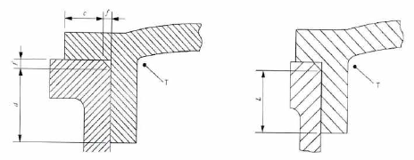
6.3.1.1. Explosion-proof joints of tube-type, cylindrical without bolt holes as shown in Figure 1.
Note:
c - Width of the explosion-proof joint surface, mm.
d - Width of the explosion-proof joint cylindrical section, mm.
f - Clearance of the chamfered edge, mm.
L - Minimum width of the explosion-proof joint, mm; L = c + d with the condition: c ≥ 3,0 mm, f ≤ 1,0 mm.
T - Inside of the equipment housing.
Figure 1. Explosion-proof joint of tube-type, cylindrical without bolt holes.
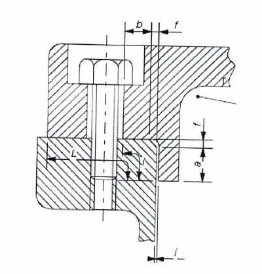
6.3.1.2. Explosion-proof joints of tube-type, cylindrical with bolt holes as shown in Figure 2.
Note:
a - Width of the explosion-proof joint cylindrical section, mm.
b - Width of the explosion-proof joint flat section to the bolt hole, mm.
i - Clearance of the cylindrical section of the explosion-proof joint, mm.
l - Minimum distance from inside the equipment to the bolt hole mm; l = a + b if i ≤ 0,2 mm.
L - Minimum width of the explosion-proof joint, mm.
T - Inside of the equipment housing.
Figure 2. Explosion-proof joint of tube-type, cylindrical with bolt holes.
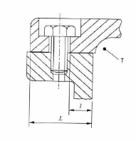
6.3.1.3. Explosion-proof joints of flat flange type as shown in Figure 3.
Note:
l - Minimum distance from inside the equipment to the bolt hole mm.
L - Minimum width of the explosion-proof joint, mm.
T - Inside of the equipment housing.
Figure 3. Explosion-proof joint of flat flange type.
6.3.1.4. The minimum distance from inside the equipment to the bolt hole must comply with the provisions in Table 1.
Table 1. Minimum distance from inside the equipment to the bolt hole.
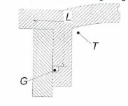
6.3.1.5. Explosion-proof joints of flange type with gasket as shown in Figure 4.
Note:
G - Gasket.
L - Minimum width of the explosion-proof joint, mm.
T - Inside of the equipment housing.
Figure 4. Explosion-proof joint of flange type with gasket.
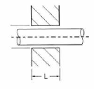
6.3.1.6. Explosion-proof joints of rotating shaft type as shown in Figure 5.
Note:
nh cơ - Minimum width of the explosion-proof joint, mm.
Figure 5. Explosion-proof joint of rotating shaft type.
When it is necessary to operate through the wall of the non-penetrating explosion-proof enclosure, the width of the joint must comply with Article 7 of TCVN 10888-1:2015 (IEC 60079-1:2014).
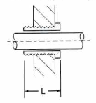
6.3.1.7. Explosion-proof joints of rotating shaft type with bushings as shown in Figure 6.
Note:
nh cơ - Minimum width of the explosion-proof joint, mm.
Figure 6. Explosion-proof joint of rotating shaft type with bushings.
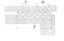
6.3.1.8. Explosion-proof joints of threaded type must comply with Clause 5.2.8 and 5.3 of TCVN 10888-1:2015 (IEC 60079-1:2014), as shown in Figure 7.
Note:
T - Thread pitch.
Y - Thread engagement length, mm.
α - Thread apex angle, degrees.
Figure 7. Explosion-proof joint of threaded type.
6.3.2. Width and minimum clearance of explosion-proof joints:
6.3.2.1. For joints in the form of: Plug, cylindrical, flanged, rotating shaft: As specified in Table 2.
Table 2. Width and minimum clearance of explosion-proof joints
6.3.2.2. For threaded joints, follow the requirements below:
6.3.2.2.1. At least five threads must be engaged.
6.3.2.2.2. Thread pitch ≥ 0.7 mm.
6.3.2.2.3. Thread angle equal to 60° (± 5°).
6.3.2.2.4. Thread engagement length ≥ 5 mm for V ≤ 100 cm3.
6.3.2.2.5. Thread engagement length ≥ 8 mm for V > 100 cm3.
6.3.3. Special clamping mechanism
All explosion-proof joints using bolt clamping must have anti-loosening washers and can only be opened with tools.
6.3.4. Interlocking mechanisms must ensure proper functioning.
6.3.5. Quick-opening covers must have interlocking mechanisms; they can only be opened after power has been cut off and the interlocking mechanism has been released.
6.3.6. Cable entry and exit ports must:
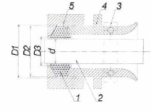
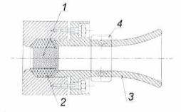
6.3.6.1. Be securely fastened to the motor housing and have all necessary components to seal and clamp the cable, one of the types of cable ports as shown in Figure 11.
Note:
1 - Rubber sealing ring for cable.
2 - Rubber-insulated cable.
3 - Cable clamping detail.
4 - Detail for cable entry to compress rubber gasket.
5 - Equipment housing.
d - Outer diameter of rubber-insulated cable, mm.
D1 - Inner diameter of cable port, mm.
D2, D3 - Outer, inner diameters of rubber gasket, mm,
Figure 11. Cable port when connected
6.3.6.2. The maximum distance between the cable port, gasket, and rubber-insulated cable as specified in Table 3.
Table 3. Maximum distance between cable port, gasket, and rubber-insulated cable
6.3.6.3. Cable port details must be tightened to ensure sealing performance.
6.3.6.4. Rubber gaskets must not crack, must be resilient, and the cable must not be stretched or bent during assembly and operation.
6.3.6.5. In cable ports using insulating filler material, upon curing, there must be no cracks.
6.3.6. Unconnected cable ports must be sealed as shown in Figure 12, or another method with equivalent sealing.
Note:
1 - Sealing plug.
2 - Rubber sealing ring.
3 - Detail for cable entry to compress.
4 - Cable clamping detail.
Figure 12. Unconnected cable port
6.4. Light-transmitting elements
Light-transmitting elements must comply with Article 9 of TCVN 10888-1:2015 (IEC 60079-1:2014) and Article 26 of TCVN 10888-0:2015 (IEC 60079-0:2011).
6.5. Material for shell construction
6.5.1. Non-metallic material
Non-metallic materials used to manufacture parts, components, and sections of the motor housing must meet the requirements set out in Article 7 of TCVN 10888-0:2015 (IEC 60079-0:2011).
6.5.2. Metallic material
Metallic materials used to manufacture parts, components, and sections of the explosion-proof motor housing must comply with the provisions of Article 8 of TCVN 10888-0:2015 (IEC 60079-0:2011).
6.6. Insulation tubes (porcelain inserts) and wire terminals for electrical connections through the housing walls must comply with Article 11 of TCVN 10888-0:2015 (IEC 60079-0:2011) and ensure they are not damaged during wiring.
6.7. Connection means and cable compartments must comply with the provisions of Articles 14 and 15 of TCVN 10888-0:2015 (IEC 60079-0:2011).
6.8. Relative dielectric strength of insulation materials used in explosion-proof starters must comply with the provisions of Article 4.4.1 of IEC 60079-7:2015, relative dielectric strength of solid insulation materials (CTI) as specified in Table 4.
Table 4. Relative Dielectric Strength
Insulation materials used in circuits operating at voltages exceeding 250 V or carrying currents greater than 16 A must have a CTI value of no less than 400.
6.9. Requirements for clearances and creepage distances
Requirements for clearances between live parts and creepage distances on insulating surfaces must comply with the provisions of Articles 4.3, 4.4 of IEC 60079-7:2015 and as specified in Table 5.
Table 5. Clearances and Creepage Distances
6.10. Requirements for parts of explosion-proof starters with "i" flameproof protection type must ensure the following requirements:
6.10.1. The outer enclosure protection level of the explosion-proof starter (IP code) must be at least IP54 as specified in TCVN 4255-2008 (IEC 60529:2001).
6.10.2. Components used in auxiliary circuits and other devices must comply with the provisions of TCVN 7079-11:2002 or IEC 60079-11:2015.
6.10.3. Electrical circuit parameters R, L & C must ensure that when tested and evaluated according to the requirements of standard TCVN 7079-11:2002 or IEC 60079-11:2015, they do not ignite the test gas mixture by sparks.
6.10.4. Any thermal effects generated in the spark-safe circuits must ensure that they do not ignite the gas mixture due to surface heating.
6.10.5. Electrical circuits must be isolated from each other and from the equipment.
7. Technical requirements for explosion-proof starters used in underground mines
7.1. Operating mode of explosion-proof starters:
7.1.1. Must operate stably within a supply voltage range of 0.85 to 1.1 times the rated voltage.
7.1.2. Must ensure stable operation under the following modes:
7.1.2.1. Continuous;
7.1.2.2. Intermittent - Continuous (8 hours);
7.1.2.3. Short-term repetitive;
7.1.2.4. Short-term.
7.2. Requirements for electrical diagrams and structure
7.2.1. The electrical circuit of the explosion-proof starter must include:
7.2.1.1. Short-circuit protection;
7.2.1.2. Overload protection;
7.2.1.3. Loss of voltage protection;
7.2.1.4. Protection against phase loss from the power supply grid;
7.2.1.5. Protection for control circuits when there is an open circuit or short circuit in remote control wires;
7.2.1.6. Interlocking between electrical and mechanical starting devices for dual starting, ensuring that only one contactor is energized;
7.2.1.7. Ground fault interlock protection for the outgoing circuit to the load;
7.2.1.8. Lockout of starting after overcurrent protection has been activated;
7.2.1.9. There must be signals indicating the operation of starting, the effect of ground fault interlocks, and various types of protection;
7.2.1.10. Function to test the operation of overcurrent protection devices and ground fault interlocks;
7.2.2. Requirements for the structure of explosion-proof starters;
7.2.2.1. Electrical circuit components must be placed in compartments with quick-opening covers that can be inspected and adjusted during operation;
7.2.2.2. Quick-opening covers must have interlocking mechanisms;
7.2.2.3. There must be schematic diagrams and wiring diagrams;
7.2.2.4. Compartments of explosion-proof starters:
7.2.2.4.1. Containing elements that frequently produce sparks during operation must be placed in non-explosion-proof enclosures type "d" in accordance with TCVN 10888-1:2015 (IEC 60079-1:2011);
7.2.2.4.2. Not containing elements that frequently produce sparks must be protected from explosions with enhanced safety type "e" in accordance with TCVN 7079-7:2002 or IEC 60079-7:2015;
7.2.2.5. Remote control circuits and auxiliary circuits of explosion-proof starters must be spark-safe circuits type "i" with safety level "ia" or "ib" according to TCVN 7079-11:2002 or IEC 60079-11:2011;
7.2.2.6. Control and protection units must be designed to prevent incorrect installation;
7.2.2.7. When the outer casing of control units and protection units contains integrated remote control devices and electrical interlocks, the protection rating must be manufactured at least IP40 as specified in TCVN 4255: 2008 (IEC 60529: 2001);
7.3. Load-carrying capacity of explosion-proof starters;
7.3.1. The allowable current on the terminals of the starter when operating continuously for 8 hours as specified in Table 6;
Table 6. Allowable Current on Terminals
7.3.2. Operating conditions of the starter when working in short-term mode as specified in Table 7;
Table 7. Operating Conditions of Starters Working in Short-Term Mode
7.3.3. Limiting and stable breaking capacity of the current passing through shall not be less than the values in Table 8 for rated voltage up to 660 V; in Table 9 for rated voltage up to 1140 V;
Table 8. Current and Breaking Capacity with Starter Voltage Up to 660 V
Table 9. Current and Breaking Capacity with Starter Voltage Up to 1140 V
7.4. Requirements for the functions of explosion-proof starters;
7.4.1. The starter must:
7.4.1.1. Close reliably at any value within the range of 85% to 110% of the rated voltage Ue;
7.4.1.2. Open when the voltage drops below the rated voltage Ue:
7.4.1.2.1. Below 65% for alternating current;
7.4.1.2.2. From 10% to 60% for direct current;
7.4.1.3. Have short-circuit, overload, and ground fault interlock protection circuits;
7.4.1.4. Have local and remote control functions via control buttons or separate installed sensor contacts. Remote control circuits outside must be spark-safe circuits;
7.4.2. An engaged starter must not automatically disconnect when the voltage on the coil drops to 0.65 Ue;
7.4.3. The control circuit of the starter must allow connection of thermal protection devices integrated into electric motors;
7.4.4. The circuit of the starter with current over 125 A must have a power supply of 18 VAC to 36 VAC, with a maximum power of 75 VA for signal, control, and local lighting circuits;
7.4.5. Protective devices must keep the starter in the off position until the fault is cleared;
7.4.6. The output of the explosion-proof starter must have overvoltage protection during closing and opening by means of an RC protective device;
7.5. Durability requirements;
7.5.1. The mechanical durability of the starter must reach at least one of the following values selected from the series: 1x10^6, 2x10^6, 3x10^6, 5x10^6, 10x10^6 cycles of closing and opening;
7.5.2. The durability of the main contacts of the starter must be at least one of the following values selected from the series:
7.5.2.1. For type AC-3: 50,000, 100,000, 500,000, 800,000, 1,000,000, 1,250,000, 1,600,000, 2,000,000 cycles of closing and opening;
7.5.2.2. For type AC-4: 20,000, 50,000, 80,000, 100,000, 125,000, 160,000, 250,000, 300,000, 500,000 cycles of closing and opening;
7.6. Insulation requirements;
7.6.1. Insulation resistance of the power circuit of the explosion-proof starter:
7.6.1.1. In new condition before use: Not less than 10 MΩ;
7.6.1.2. In hot state (corresponding to rated load current): Comply with the provisions of Clause 16 Article 106 QCVN 01: 2011/BCT;
7.6.1.3. Not less than 0.3 MΩ, after moisture resistance testing;
7.6.2. The insulation of the starter must withstand three-phase alternating voltage test at 50 Hz for 1 minute as specified in Table 10;
Table 10. Values of Insulation Withstand Voltage Test
7.7. Short-Circuit Protection;
7.7.1. Explosion-proof starters must have adjustable overcurrent protection.
7.7.2. The scope of overcurrent protection must be within the limit from 3 to 10 times the rated current of the component.
7.7.3. The operational error of the overcurrent protection at each setting point in the air environment:
7.7.3.1. Must not exceed ± 10% at a temperature of (25 ± 10) °C.
7.7.3.2. Is supplemented by ± 5% of the value specified in Clause 7.3.4.2.1 at temperatures from -10 °C to +15 °C and from +35 °C to +60 °C.
7.7.4. The total cut-off time for starting from the explosion-proof room when the overcurrent protection acts must not exceed 0.15 seconds.
7.8. Overload protection must have characteristics dependent on time and current to protect electric motors.
7.8.1. When thermal relays are used for overload protection, the characteristics dependent on time and current must meet the requirements specified in Table 10.
Table 10. Operating characteristics of overload protection
7.8.2. When electronic overload protection devices are used, their characteristics must meet the requirements specified in Table 11.
Table 11. Characteristics of electronic overload protection devices
7.9. Requirements for earth leakage interlocking switches.
7.9.1. Earth leakage interlocking switches must not allow the starting contactor to close when the insulation resistance of the circuit behind the starting contactor decreases to the specified value.
7.9.2. The actuating resistance value of the earth leakage interlocking switch circuit is specified in Table 12.
Table 12. Actuating resistance parameters of earth leakage interlocking switches
7.9.3. When the insulation resistance of the network behind the starting contactor to ground increases to 1.5 times the actuating value, the earth leakage interlocking switch must reset.
7.10. Requirements for permissible temperature rise.
7.10.1. The maximum permissible temperature rise of the starting contactor when operating at rated current with load current passing through the starting contactor under ambient temperature conditions of 35 °C must not exceed the values specified in Table 13.
Table 13. Maximum permissible temperature rise
7.10.2. The maximum surface temperature of the explosion-proof starting contactor must not exceed the temperature classification value specified in Clause 5.3.2.2 of Table 2 of TCVN 10888-0:2015 (IEC 60079-0:2011).
7.11. For removable plug connectors, switches, and push buttons, components with electroplated layers and soldered silver or other materials resistant to internal environmental effects may be used.
7.12. Each starting contactor must have at least two auxiliary circuit contact spares connected to the safe spark or unsafe spark cable connection terminals.
7.13. In the motor cable outlet compartment of the starting contactor, there must be at least two wire clamps to safely connect the spark-safe and spark-safe circuits.
7.14. The input cable clamp of the starting contactor must ensure connection to both main cables and flexible cables, taking into account the allowable working current as specified in Table 6 of this Technical Standard.
7.15. Explosion-proof starting contactors must have at least two cable entries for the control circuit.
7.16. The quick-opening cover of the contactor compartment must allow opening and closing at least 4,000 times.
7.17. Starting contactors must have an electrical schematic diagram describing the wiring of the starting contactor.
8. Requirements and testing methods
8.1. General requirements
Tests must be conducted under the following conditions:
8.1.1. Ambient temperature from -20 °C to +40 °C.
8.1.2. Relative humidity up to (98 ± 2)% at 35 °C.
8.1.3. Oxygen content is 21% by volume;
8.1.4. No flammable gases, toxic gases, or corrosive vapors.
8.2. Testing of actuating parameters
8.2.1. Test contents are carried out according to Appendix C of this Technical Standard, test values according to TCVN 6592-1:2009 (IEC 60947-1:2007), TCVN 6592-4-1:2009 (IEC 60947-4-1:2002).
8.2.2. Actuating parameters must be monitored in the operating position and when the explosion-proof starting contactors are tilted 15 degrees forward, backward, left, and right. At each position, the following must be performed:
8.2.2.1. Three open-close operations at ambient temperature with voltages of 0.85 and 1.1 times the rated voltage.
8.2.2.2. Low voltage check. Perform three no-load contactor closures in the cold state with a voltage of 0.85 Ue, then reduce the voltage to 0.65 Ue. The magnetic system of the contactor must not release.
8.3. Local manual shutdown and remote shutdown.
8.4. Signal check when the starting contactor has closed.
8.5. Mechanical interlock check
8.5.1. Open the cover with the interlocked disconnect switch closed;
8.5.2. Close the interlocked disconnect switch when the cover is open or not fully closed;
8.5.3. Disconnect the interlocked disconnect switch when the starting contactor is closed;
8.5.4. Measure the handgrip force for closing and opening;
8.5.5. Check the electrical-mechanical interlock between the disconnect switch and the contactor by pressing the "Stop" button and opening the disconnect switch;
8.5.6. Interlock mechanisms are considered to have passed the test if there are no failures or malfunctions of the interlock mechanisms in all tests.
8.6. Insulation testing: The insulation of the explosion-proof starting contactor is tested according to Clause 7.6 of this Technical Standard.
8.7. Remote control circuit testing
When the remote control circuit is broken or short-circuited, the starting contactor must:
8.7.1. Not be able to close in the open position;
8.7.2. Trip when in the closed position.
8.8. Overcurrent protection testing must:
8.8.1. Use sinusoidal alternating current, frequency 50 Hz;
8.8.2. Set the actuating current higher than the set value by 10% to 15% of the rated current;
8.8.3. The overcurrent protection must operate and trip the starting contactor, while the signal light must illuminate.
8.9. Results of overcurrent protection testing
8.9.1. The average value of three tests is the actual protective operating current;
8.9.2. The error of overcurrent protection at each setting point shall not exceed ± 10 % at ambient temperature (25 ± 10) °C;
8.9.3. Testing is conducted at three points within the range of settings: "lowest", "middle", and "highest";
8.10. Determination of short-circuit breaking time
8.10.1. Testing with an impact current and setting current multiplier of 1.5 times;
8.10.2. Conducted at three points on the protection scale: low, middle, and high;
8.10.3. The impact time is the highest value of ten test results at the setting point, which shall not exceed 0.15 seconds;
8.11. Overload protection testing
8.11.1. Use alternating current sine wave with a frequency of 50 Hz for testing;
8.11.2. Test results must comply with the parameters specified in Table 10 and Table 11;
8.11.3. An indicator light signal must be activated when overload protection operates;
8.11.4. There must be a device to record the breaking time of the protection;
8.12. Ground fault interlock testing
8.12.1. Testing at rated voltage;
8.12.2. Use adjustable resistors to connect between phase wire and ground to determine the impact resistance (three-phase and single-phase);
8.12.3. Test the impact time when there is a single-phase ground fault with a resistance of 1 kΩ;
8.12.4. When the ground fault interlock activates, the indicator light signal must illuminate;
8.12.5. Test results must comply with the provisions in Table 12, Clause 7 of this Technical Standard;
8.13. Double-start check: Controlling the forward contactor to close, the reverse contactor must not operate;
8.14. Non-reversing start check: Isolating switches are closed in two opposite directions, the starting mechanism must operate normally;
8.15. Explosion-proof protection testing
The testing method is carried out according to the provisions of TCVN 10888-0:2015 (IEC 60079-0:2011) and TCVN 10888-1:2015 (IEC 60079-1:2014);
8.16. Spark safety testing
The testing method is carried out according to the provisions of TCVN 7079-11:2002 (IEC 60079-11:2011);
9. Labeling requirements
Information recorded on the label of explosion-proof starters used in underground mines must include minimum information as stipulated in Clause 1, Article 10 of Decree No. 43/2017/NĐ-CP dated April 14, 2017 of the Government regarding product labeling, and parts of the starter must display the following contents:
9.1. Contents recorded on the label
9.1.1. Type, model;
9.1.2. Rated voltage, V;
9.1.3. Rated current, A;
9.1.4. Rated frequency, Hz;
9.1.5. Explosion-proof protection type;
9.1.6. Enclosure protection rating;
9.1.7. Explosion-proof certificate number;
9.1.8. Factory serial number;
9.1.9. Spark-safe circuit parameters (if applicable);
9.1.10. Year of manufacture;
9.1.11. Weight, kg;
9.2. Requirements for the label plate and position
The label plate must be produced from white steel or copper sheet with a thickness of 1.5 mm, the information engraved must have a depth of no less than 0.5 mm, and must be arranged in a place that is easy to see and read, affixed to the housing using nails or screws;
9.3. Electrical schematic diagram plate
The electrical schematic diagram describing the operation principle and wiring of the explosion-proof starter must be attached inside the housing wall;
8.2. Domestic-produced TNP1 explosive must declare compliance according to Circular No. 28/2012/TT-BKHCN dated December 12, 2012, issued by the Minister of Science and Technology regarding declaration of conformity to standards and technical regulations and methods of conformity assessment (hereinafter referred to as Circular No. 28/2012/TT-BKHCN) and Circular No. 02/2017/TT-BKHCN dated March 31, 2017, issued by the Minister of Science and Technology amending and supplementing certain provisions of Circular No. 28/2012/TT-BKHCN dated December 12, 2012, issued by the Minister of Science and Technology regarding declaration of conformity to standards and technical regulations and methods of conformity assessment (hereinafter referred to as Circular No. 02/2017/TT-BKHCN).
10. Conformity Assessment Requirements
10.1. Explosion-proof starters within the scope of this Standard must declare conformity in accordance with technical safety regulations in Part II of this Technical Standard, affix the conformity mark (CR mark) before entering the market, and label products in accordance with current regulations; they must be inspected and tested during operation in accordance with Parts III and IV of this Technical Standard;
10.2. Domestic-produced and imported explosion-proof starters must implement conformity declaration in accordance with Circular No. 28/2012/TT-BKHCN dated December 12, 2012 of the Minister of Science and Technology on conformity declaration and inspection methods, and Circular No. 02/2017/TT-BKHCN dated March 31, 2017 of the Minister of Science and Technology amending and supplementing some articles of Circular No. 28/2012/TT-BKHCN (hereinafter referred to as Circular No. 28/2012/TT-BKHCN and Circular No. 02/2017/TT-BKHCN);
10.3. Imported explosion-proof starters must register for state quality inspection of imported goods in accordance with Circular No. 36/2019/TT-BCT dated November 29, 2019 of the Ministry of Industry and Trade on managing the quality of products and goods in Group 2 under the responsibility of the Ministry of Industry and Trade;
10.4. Declaration of Conformity
10.4.1. Declaration of conformity for explosion-proof starters must be based on the certification results of organizations certified to operate in the field according to Decree No. 107/2016/NĐ-CP dated July 1, 2016 of the Government on business activities related to conformity assessment services (hereinafter referred to as Decree No. 107/2016/NĐ-CP); Decree No. 154/2018/NĐ-CP dated November 9, 2018 of the Government amending and supplementing, abolishing some provisions on investment and business conditions in the management sector of the Ministry of Science and Technology (hereinafter referred to as Decree No. 154/2018/NĐ-CP) and some provisions on specialized inspections or recognized according to Circular No. 27/2007/TT-BKHCN dated October 31, 2007 of the Minister of Science and Technology guiding the signing and implementation of Mutual Recognition Agreements on conformity assessment results (hereinafter referred to as Circular No. 27/2007/TT-BKHCN);
10.4.2. Conformity Certification
10.4.2.1. For domestically produced explosion-proof starters:
Conformity certification according to Method 5 "Typical sample testing and production process evaluation; monitoring through sampling at the production site or on the market combined with production process evaluation" at the explosion-proof starter production facility in accordance with Clause 1, Article 5 of Circular No. 28/2012/TT-BKHCN;
10.4.2.2. For imported explosion-proof starters:
A conformity declaration under method 7 "Product batch testing and evaluation" or method 5 "Typical sample testing and production process assessment; monitoring through sampling at the place of production or on the market combined with production process assessment" shall be issued upon request from foreign manufacturing establishments as stipulated in Clause 1, Article 5 of Circular No. 28/2012/TT-BKHCN.
10.4.3. Testing for certification purposes must be conducted by one of the following organizations:
10.4.3.2. Testing organizations designated by the Ministry of Industry and Trade pursuant to Decree No. 74/2018/NĐ-CP and Decree No. 154/2018/NĐ-CP.
10.4.4. The conformity mark must comply with Clause 2, Article 4 of the regulations on standard compliance certification, conformity certification, and standard announcement, conformity announcement issued together with Circular No. 28/2012/TT-BKHCN.
10.4.5. Procedures, formalities, and documentation for conformity announcement
Procedures, formalities, and documentation for conformity announcement for domestically produced and imported explosion-proof starting devices shall be carried out in accordance with Circular No. 36/2019/TT-BCT dated November 29, 2019, issued by the Minister of Industry and Trade regarding product quality management under the responsibility of the Ministry of Industry and Trade.
11. Requirements for management file of explosion-proof starting devices used in underground mines
11.1. Must have complete technical documents provided by the manufacturer, including: Transportation, usage, maintenance, and storage guidelines. In case of foreign language technical documents, they must be translated into Vietnamese and notarized.
11.2. Organizations and individuals using explosion-proof starting devices must establish a management file from the time of initial use, including:
11.2.1. Approved design selection of explosion-proof starting devices used in underground mines.
11.2.2. Construction design and installation location of explosion-proof starting devices.
11.2.3. Post-installation acceptance report.
11.2.4. Completion report of installation.
11.2.5. Calibration and testing report.
11.2.6. Operating procedures.
11.2.7. Record book of technical safety inspection results and operational status monitoring of explosion-proof starting devices used in underground mines.
11.2.8. Safety regulations, procedures for transportation, installation, inspection, operation, maintenance, repair, and storage of explosion-proof starting devices used in underground mines.
12. Requirements for inspection during operation
12.1. Inspection and evaluation of technical features during operation shall be carried out according to QCVN QTĐ-5:2009/BCT, QCVN 01:2011/BCT, TCVN 4255:2008 (IEC 60529:2001), TCVN 6592-1:2009 (IEC 60947-1:2007), TCVN 6592-4-1:2009 (IEC 60947-4-1:2002), TCVN 10888-0:2015 (IEC 60079-0:2011), TCVN 10888-1:2015 (IEC 60079-1:2014), TCVN 7079-7:2002, TCVN 7079-11:2002, TCVN 7079-17:2003, IEC 60079-7:2015, (IEC 60079-11:2011, IEC 60079-17:2013.
12.2. Inspection methods:
12.2.1. Visual inspection: Inspection that does not require the use of equipment or tools.
12.2.2. Direct inspection: Inspection of external parts by visual means and determination of defects using tools and equipment. Direct inspection shall not involve opening the casing or disconnecting power to the device.
12.2.3. Detailed inspection: Inspection that includes direct inspection contents and determination of defects using tools and equipment. Detailed inspection requires disconnection of power and opening of the device casing.
13. Inspection period and content
13.1. Responsibility and frequency of inspection:
13.1.1. Operators or electricians on duty shall inspect each shift.
13.1.2. Deputy Chief Mechanic of the workshop or authorized person shall inspect weekly.
13.1.3. Head of the Mechanical Department or authorized person shall inspect quarterly.
13.1.4. Deputy Director of Mechanical Department or designated persons shall inspect annually.
13.2. Inspection content shall be carried out in accordance with Appendix B of this Technical Regulation.
13.3. Inspection results must be:
13.3.1. Recorded in the inspection logbook as stipulated in Appendix D of this Technical Regulation.
13.3.2. Concluded on the technical safety condition of explosion-proof starting devices used in underground mines and only allowed to be put into use or continue operation when safety standards are met.
13.4. When discovering unsafe equipment, the observer or operator must stop the operation and report to responsible persons for handling.
14. Requirements for testing and inspection
14.1. According to types of inspections and tests, these must be carried out according to technical guidance, testing methods, testing procedures, and testing equipment specified in the Technical Regulations and Standards QCVN QTĐ-5:2009/BCT, QCVN 01:2011/BCT, TCVN 4255:2008 (IEC 60529:2001), TCVN 6592-1:2009 (IEC 60947-1:2007), TCVN 6592-4-1:2009 (IEC 60947-4-1:2002), TCVN 10888-0:2015 (IEC 60079-0:2011), TCVN 10888-1:2015 (IEC 60079-1:2014), TCVN 7079-7:2002, TCVN 7079-11:2002, TCVN 7079-17:2003, IEC 60079-7:2015, (IEC 60079-11:2011, IEC 60079-17:2013.
14.1.1. Specific items and parameters of the tests and inspections must be carried out according to the technical standards applied and the manufacturer's instruction manual.
14.1.2. Measuring instruments (voltage, current, frequency, temperature, humidity meters: insulation resistance testers, gas concentration meters, methane, hydrogen) used in the tests and inspections under this Technical Regulation must be calibrated and verified according to legal metrology regulations.
14.2. Reporting and evaluating test and inspection results
Reporting and evaluating test and inspection results must clearly indicate whether the requirements of the applicable Standards and Technical Regulations are met.
14.2.1. Test and inspection pass when: Meeting the technical requirements of the applicable Standards and Technical Regulations listed in Table C of Appendix C of this Technical Regulation.
14.2.2. Test and inspection fail when: Not meeting one of the technical requirements of the applicable Standards and Technical Regulations listed in Table C of Appendix C of this Technical Regulation.
IV. IMPLEMENTATION
15. Responsibilities of organizations and individuals
15.1. Organizations and individuals related to the production, import, testing, inspection, and use of explosion-proof starters in underground mines must comply with the provisions of this Technical Regulation.
15.2. Organizations and individuals using explosion-proof starters in underground mines must:
15.2.1. Regularly inspect explosion-proof starters according to regulations, promptly report to the competent authority when discovering incidents or signs of safety risks during operation.
15.2.2. Repair, maintain, test, and inspect explosion-proof starters in accordance with the provisions of this Technical Regulation and other relevant legal documents.
15.2.3. Establish files for monitoring and safely using explosion-proof starters in underground mines as stipulated in this Technical Regulation.
15.3. Testing and inspection organizations
Testing and inspection organizations must implement the contents prescribed in this Technical Regulation and bear responsibility for the results of their tests and inspections according to current regulations.
16. Implementation Organization
16.1. The Department of Safety Technology and Industrial Environment under the Ministry of Industry and Trade shall be responsible for:
16.1.1. Providing guidance and organizing the implementation of the provisions of this Technical Regulation.
16.1.2. Inspecting and supervising the implementation of the contents prescribed in this Technical Regulation by organizations related to the use of explosion-proof starters in underground mines.
16.2. Provincial Departments of Industry and Trade shall organize inspections and supervision of the implementation of the contents prescribed in this Technical Regulation within their functions and authorities.
17. Effective Date
17.1. This Technical Regulation shall take effect from July 1, 2022.
17.2. In case the legal normative documents, technical standards, and specifications referred to in this Technical Regulation are amended, supplemented, or replaced, they shall be implemented according to the new regulations.
17.3. Organizations and individuals implementing this Technical Regulation, if encountering difficulties or obstacles during implementation, should report to the Ministry of Industry and Trade for research and resolution./.
ANNEX A
HS CODE OF THE LIST OF PRODUCTS AND GOODS
WITHIN THE SCOPE OF REGULATION OF THIS TECHNICAL REGULATION
As stipulated in Circular No. 33/2017/TT-BCT dated December 28, 2017 of the Minister of Industry and Trade amending and supplementing the HS code in the List issued together with Circular No. 29/2016/TT-BCT dated December 13, 2016 of the Minister of Industry and Trade on the List of products and goods that may cause safety risks under the management responsibility of the Ministry of Industry and Trade.
Provisions on the HS Code of Terrestrial Mobile Radio Equipment and Terrestrial Radio Relay Equipment
INSPECTION CONTENTS
I. Shift Inspection:
The shift inspection contents are specified in Table B1.
Table B1. Specifies the shift inspection contents
- Nameplates must be complete, clean, easy to read, and free from damage or faded markings that cannot be clearly seen.
II. Weekly Inspection:
In addition to the daily inspection tasks, additional contents must be inspected as specified in Table B2.
III. Quarterly inspection:
In addition to the weekly inspection tasks, additional items must be inspected according to the provisions in Table B3.
Table B3. Provisions for quarterly inspection contents
IV. Annual inspection:
In addition to the quarterly inspection tasks, additional items must be inspected according to the provisions in Table B4.
Table B4. Provisions for annual inspection contents
Serial number
1
2 Direct visual inspection
Annex C
CONTENTS OF TESTING AND INSPECTION
I. Testing and inspection contents as specified in Table C
Table C. Provisions for testing and inspection contents
Appendix D
RECORD BOOK FOR INSPECTION RESULTS
SAFETY TECHNIQUE AND MONITORING OF THE OPERATING STATUS
OF EXPLOSION-PROOF SOFT STARTERS USED IN UNDERGROUND MINES
Department, Construction Site, Workshop: …
Unit: ....
Start recording in this book from date … month … year ...
End recording in this book on date … month … year ...
Part I
Part II
Instructions for recording
Part I: Record the status of the details, equipment, and mechanisms of the soft starter after inspection.
- Column 3 records in chronological order by day and month. In the column, record the symbols:
“T” - Indicates good condition of the detail or assembly
“H” - Indicates defective condition of the detail or assembly
“CKT” - Indicates untested detail or assembly
- Remarks …(of the person assigned to inspect and record)
PART II: Record defects (defective details, degree of damage, and repair methods)
The person assigned to conduct the inspection records in column 2 the nature and degree of damage of the parts and marks the symbol "H" in Part I.
In column 3, the Manager records detailed remediation plans, the faulty parts, and the person responsible for implementing the remediation plans.
Note:
a) The person responsible for these numbers shall be technical staff specialized in mine electromechanical equipment.
b) The book must be paginated and stamped with the mine's cross-stamp.
Quarterly and annual inspection results shall not be recorded in the book but shall be documented in minutes, fully detailing all safety inspection parameters. The Deputy Director in charge of electromechanical equipment must review and sign with their stamp./.